Hein Lanz D1-333-121-34 Series User manual

$8?EPDFÏÏV Page 1 / 43
$8
S
SSI Indicators for Use with
Single-Turn or Multi-Turn SSI Encoders
%
:SSI display unit only
$
: SSI display unit with analogue output
$
: SSI display unit with two presets and outputs
$
: SSI display unit with serial interface RS232 and RS485
x
Clear LED display (15 mm / 0.59’’ size) with adjustable brightness
x
Master- or Slave operation with clock rates up to 1 MHz
x
Suitable for all SSI formats from 8 to 32 bits
x
Numerous supplementary functions like Linearization, Bit Blanking etc.
Operating Instructions

$8?EPDFÏÏV Page 2 / 43
S
Safety Instructions
x
This manual is an essential part of the unit and contains important hints about
function, correct handling and commissioning. Non-observance can result in
damage to the unit or the machine or even in injury to persons using the
equipment!
x
The unit must only be installed, connected and activated by a qualified electrician
x
It is a must to observe all general and also all country-specific and application-
specific safety standards
x
When this unit is used with applications where failure or maloperation could cause
damage to a machine or hazard to the operating staff, it is indispensable to meet
effective precautions in order to avoid such consequences
x
Regarding installation, wiring, environmental conditions, screening of cables and
earthing, you must follow the general standards of industrial automation industry
x
- Errors and omissions excepted –
General instructions for cabling, screening and grounding can be found in the
SUPPORT section of our website http://
WWWHEINLANZCOM
Version:
Description:
03b /af/hk//Feb 08
Range of PM-Factor, SSI zero position and preselection mode
1 / 2 increase to [-199999, 999999];
load on the current output max. 300 Ohm
07a = 08a/kk/hk/Apr.09
Extensions: Linearization, Activation of serial transmission
09a/kk/hk/Feb.10
Extension from 25 to 32 bits
10a/kk/hk/June.10
Missing encoder alarm, remote start of serial string
10b/af/nw/March 13
Correction of the basic parameter “Analogue Characteristics”

$8?EPDFÏÏV Page 3 / 43
T
Table of Contents
1. Terminal Assignment ................................................................................................... 4
1.1. Power Supply ................................................................................................................................5
1.2. Aux. Voltage Output .....................................................................................................................5
1.3. Control Inputs A, B and C .............................................................................................................5
1.4. Adjustable Analogue Output ($ only)................................................................................6
1.5. Optocoupler (transistor) outputs ($ only) ..........................................................................6
1.6. Serial RS232 / RS485 interface ($ only) ...........................................................................7
2. How to Operate the Front Keys .................................................................................... 8
2.1. Normal display state ....................................................................................................................8
2.2. Selection and Setting of Parameters ...........................................................................................9
2.3. Teach operation..........................................................................................................................10
2.4. Set all parameters to “Default“ .................................................................................................10
2.5. Code Locking of the Keypad .......................................................................................................10
3. The Operator Menu.................................................................................................... 11
3.1. Overview of Basic Parameters ...................................................................................................11
3.2. Overview of Operational Parameters.........................................................................................12
4. Setup Procedure......................................................................................................... 13
4.1. Basic Parameters........................................................................................................................13
4.2. Operational Parameters..............................................................................................................15
4.3. Additional Parameters for the Analogue Output (model $)............................................18
4.4. Additional Parameters for Preselections and Switching Outputs (model $) ................20
4.5. Additional Parameters for Units with Serial Interface (model $)..................................22
5. Hints for Application .................................................................................................. 26
5.1. Master and Slave Operation ......................................................................................................26
5.2. Evaluation of Encoder Bits..........................................................................................................27
5.3. Scaling of the Display.................................................................................................................28
5.4. Basic Modes of Operation..........................................................................................................29
5.5. Testing Functions........................................................................................................................33
5.6. Error Messages...........................................................................................................................33
6. Special Functions....................................................................................................... 34
6.1. Linearization ...............................................................................................................................34
6.2. Manual Input or „Teaching“ of the Interpolation Points ...........................................................36
7. Technical Appendix.................................................................................................... 38
7.1. Dimensions .................................................................................................................................38
7.2. Technical Specifications.............................................................................................................39
7.3. Parameter-List ............................................................................................................................40
7.4. Commissioning Form ..................................................................................................................42

$8?EPDFÏÏV Page 4 / 43
*1'
9&',1
,QSXW$
,QSXW%
*1'
9'&287
*1'DQDORJXH
9DQDORJXH
P$DQDORJXH
3(*1'
9$&
9$&
9$&
&/.
&/.
'$7
'$7
,QSXW&5HVHW
$:
:Display with two presets and outputs
*1'
9&',1
,QSXW$
,QSXW%
,QSXW&5HVHW
*1'
9'&287
&20
287
287
3(*1'
9$&
9$&
9$&
&/.
&/.
'$7
'$7
$
: Display with serial interface
*1'
9&',1
,QSXW$WUDQVP
,QSXW%
,QSXW&5HVHW
*1'
9'&287
7['%
3(*1'
9$&
9$&
9$&
&/.
&/.
'$7
'$7
*1'
5['$
1.ÏTerminal Assignment
$
:Displayunitonly
All connections are as shown below, except for terminals 8, 9 and 10 which are unconnected
%
: Display with analogue output

$8?EPDFÏÏV Page 5 / 43
1
1.1. Power Supply
The unit accepts DC supply from 17 V to 30 V when using terminals 1 and 2. The consumption
depends on the level of the supply voltage
(typical 130mA at 30V or 190mA at 17V, plus current taken from aux. output).
For AC supply the terminals 0 VAC, 115 VAC or 230 VAC can be used.
The total AC power is 7.5 VA.
The diagrams below show a dotted line for grounding to PE.
This connection is not really necessary, neither for safety nor for EMC. However, for some
applications, it may be desirable to ground the common potential of all signal lines.
When using this earthing option, please observe:
xAll terminals and potentials marked “GND“ will be earthed.
xPlease avoid multiple earthing, i.e. when you use a DC power supply where
the Minus is already connected to earth etc.
1.2. Aux. Voltage Output
Terminal 7 provides an auxiliary output of 24 VDC / 120 mA max. for supply of sensors and
encoders.
1.3. Control Inputs A, B and C
With models $, input A is used to activate a serial transmission (rising edge, see
4.5.2). Input B is not in use.
Input C operates as a Set / Reset input (static function, active "HIGH", see 5.3).
In the basic setup menu, the inputs can be configured to PNP (signal must switch to +) or to
NPN (signal must switch to -). This configuration is valid for all three inputs at a time.
The factory setting is always PNP.
x
Where NPN setting is used, please observe:
Open NPN inputs will always represent a logical HIGH state
Consequently, Input C has to be connected to GND externally to allow normal operation.ÏIf
unconnected, the unit would be kept in a continuous Reset state.
With models
$
, also Input A must be tied to GND, and opening this connection willÏ
generate a rising edge to start a serial transmission
x
Where your use 2-wireNAMUR type sensors, please select NPN, connect the negativeÏ
wire of the sensor to GND and the positive wire to the corresponding input.

$8?EPDFÏÏV Page 6 / 43
T
Typical input circuit of control input
313
N
*1'
*1'
9LQW
,QSXW
N
*1'
,QSXW
9LQW
131
The minimum pulse duration on the Reset input (C) must be 5 msec.
1.4. AdjustableAnalogueOutput
$
only)
A voltage output is available, operating in a range of 0 ... +10 V or –10 V ... +10 V according to
setting. At the same time, a current output 0/4 – 20 mA is available. Both outputs refer to the
GND potential and the polarity changes with the sign in the display. The outputs are
proportional to the display value and provide a 14 bits resolution.
The maximum current on the voltage output is 2 mA, and the load on the current output can vary
between 0 and max. 300 ohms.
The response time of the analogue output to changes of the encoder position is appSox. 7 NTFD
1.5. Optocoupler (transistor) outputs (
$
only)
The outputs provide programmable switching characteristics and are potential-free. Please
connect terminal 8 (COM+) to the positive potential of the voltage you like to switch
(range 5V....35V). You must not exceed the maximum output current of 150 mA. Where you
switch inductive loads, please provide filtering of the coil by means of an external diode.
The optocoupler outputs provide a response time of approx. 5 msec with resistive load.
Opto Opto
33 R
Com+ (5 ... 35 V)
Output 1 (max. 150 mA)
Output 2 (max. 150 mA)
33 R

$8?EPDFÏÏV Page 7 / 43
1
1.6. Serial RS232 / RS485 interface (
$ÏONLY
)
Ex factory the unit is set to RS232 communication. This setting can be changed to RS485
(2-wire) by means of an internal DIL switch. To access the DIL switch, you must remove the
screw terminal connectors and the backplane. Then pull the board to the rear to remove the
PCB from the housing.
21',3
',/6ZLWFK
Removal of the back plane Location of the DIL switch
x
Never set DIL switch positions 1 and 2 or DIL switch positions 3 and 4 to
“ON” at the same time!
x
After setting the switch, shift the print carefully back to the housing and
avoid damage of the front pins for connection to the front keypad plate.
5[' 5['
7['7['
*1'
6FUHHQ
3&
'
9
6XE'
10
8
Connection of the RS232 interface
3/&
'
$
%
$
%
Connection of the RS485 interface

$8?EPDFÏÏV Page 8 / 43
2
2. How to Operate the Front Keys
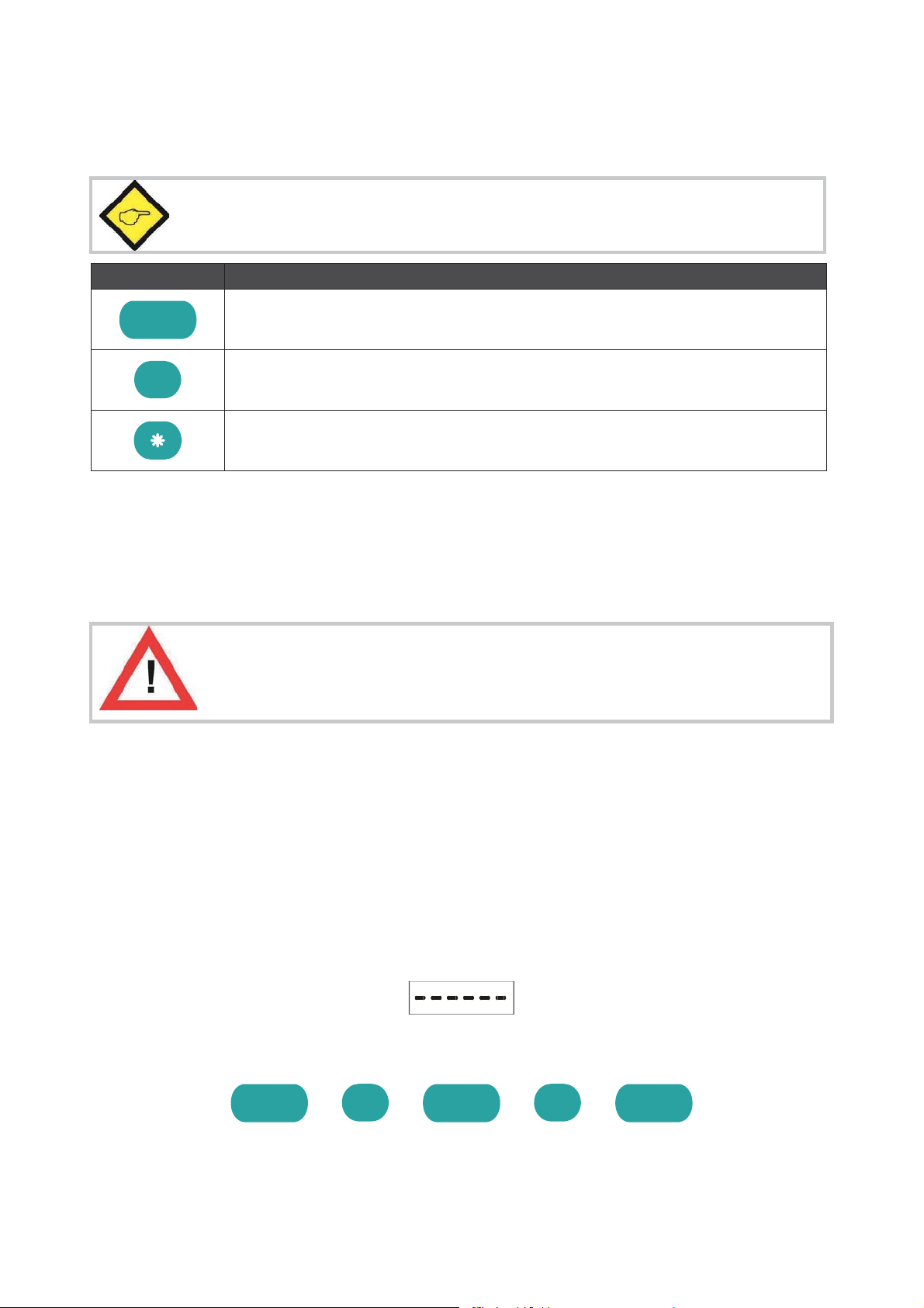
For setup and other operations the unit uses three front keys which subsequently will be
denominated as follows:
«
ENTER
(Input)
SET
(Setting)
Cmd
(Command)
The functions of the keys are depending on the actual operating state of the unit.
The following three operating states apply:
x
Normal display state
x
Setup state
a.) Basic setup
b.) Operational parameter setup
x
Teach operation
2.1. Normal display state
You can only change over to other operation states while the unit is in the
n
normal display state.
Change over to
Key operration
Basic setup
Keep EENTER and SSET down simultaneously for 3 seconds
Operational
p
parameter setup
Keep EENTER down for 3 seconds.
Teach operation
Keep CCmd down for 3 seconds
The Cmd key is only used to execute the Teach procedure with linearization. For more details
please refer to sections 6.1 and 6.2.

$8?EPDFÏÏV Page 9 / 43
2
2.2. Selection and Setting of Parameters
2.2.1. How to select a parameter
The E
ENTER
key will scroll through the menu. The S
SET
key allows to select the corresponding
item and to change the setting or the numeric value. After this, the selection can be stored by
ENTER
again, which automatically changes over to the next menu item.
2.2.2. How to change parameter settings
With numerical entries, at first the lowest digit will blink. When keeping the S
SET
key
continuously down, the highlighted digit will scroll in a continuous loop from 0 … 9 , 0 … 9.
After releasing the S
SET
key, the actual value will remain and the next digit will be highlighted
(blink). This procedure allows setting of all digits to the desired values. After the most
significant digit has been set, the low order digit will blink again and you can do corrections if
necessary.
With signed parameters, the high order digit will scroll from “0” to "9" (positive) followed by
“-“ and "-1" (negative)
2.2.3. How to store settings
To store the actual setting, press the E
ENTER
key, which will also automatically scroll forward
the menu.
At any time the unit changes from programming mode to normal display operation, when you
keep the E
ENTER
key down again for at least 3 seconds.
2.2.4. Time-out function
A “time-out” function will automatically conclude every menu level, when for a break period of
10 seconds no key has been touched. In this case, any changes which have not been confirmed
by E
ENTER
yet would remain unconsidered.
$8?EPDFÏÏV Page 10 / 43
2
2.3. Teach operation
The Time
-out function will be switched off during all Teach operations
Key
Function
«
ENTER will conclude or abort any Teach operation in progress
SET function is fully similar to normal set-up operation
Cmd will store the display value to the register and will change over to the
next interpolation point.
For details of the Teach procedure see section 6.2.
2.4. Set all parameters to “Default“
At any time you can return all settings to the factory default values.
The factory default settings are shown in the parameter listings in section 6.
When you decide to set all parameters to „default“, please be aware that all
p
previous settings
will be lost and you will need to do the whole set-up
procedure once more
To execute the „Default“ setting function:
xPower the unit down.
xPress the ENTER key.
xPower the unit up again while the ENTER key is kept down
2.5. Code Locking of the Keypad
When the code locking of the keypad has been switched on, any key access first results in
display of
To access the menu you must press the key sequence
«
«
«
within 10 seconds, otherwise the unit will automatically return to the normal display mode.

$8?EPDFÏÏV Page 11 / 43
3
3. The Operator Menu
The menu provides one section with “Basic Parameters” and another section with “Operational
Parameters”. On the display you will only find those parameters which have been enabled by
the basic settings. E.g. when the Linearisation Functions have been disabled in the basic set-
up, the associated linearization parameters will also not appear in the parameter menu.
All parameters, as good as possible, are designated by text fragments. Even though the
possibilities of forming texts are very limited with a 7-segment display, this method has proved
to be most suitable for simplification of the programming procedure.
The subsequent table shows the general structure of the whole menu only.
Detailed descriptions of all parameters will follow in section 4.
3.1. Overview of Basic Parameters
$
$
$
$
SSI_Mode
SSI_Mode
SSI_Mode
SSI_Mode
SSI_Bits
SSI_Bits
SSI_Bits
SSI_Bits
SSI_Format
SSI_Format
SSI_Format
SSI_Format
SSI_Baud Rate
SSI_Baud Rate
SSI_Baud Rate
SSI_Baud Rate
SSI_Test
SSI_Test
SSI_Test
SSI_Test
Characteristics
Characteristics
Characteristics
Characteristics
Brightness
Brightness
Brightness
Brightness
Code Locking
Code Locking
Code Locking
Code Locking
Linearization Mode
Linearization Mode
Linearization Mode
Linearization Mode
Analogue Characteristics
Preselection_Mode 1
Ser_Unit_Nr
Analogue Offset
Preselection_Mode 2
Ser_Format
Analogue Gain
Hysteresis 1
Ser_Baudrate
Hysteresis 2

$8?EPDFÏÏV Page 12 / 43
3
3.2. Overview of Operational Parameters
$
$
$
$
Preselection 1
Preselection 2
M-Factor
M-Factor
M-Factor
M-Factor
D-Factor
D-Factor
D-Factor
D-Factor
P-Factor
P-Factor
P-Factor
P-Factor
Decimal point
Decimal point
Decimal point
Decimal point
Display
Display
Display
Display
Hi_Bit (MSB)
Hi_Bit (MSB)
Hi_Bit (MSB)
Hi_Bit (MSB)
Lo_Bit (LSB)
Lo_Bit (LSB)
Lo_Bit (LSB)
Lo_Bit (LSB)
Direction
Direction
Direction
Direction
Error
Error
Error
Error
Error_Polarity
Error_Polarity
Error_Polarity
Error_Polarity
Round Loop
Round Loop
Round Loop
Round Loop
Time
Time
Time
Time
Reset
Reset
Reset
Reset
Zero Position
Zero Position
Zero Position
Zero Position
Analogue Begin
Ser_Timer
Analogue End
Ser_Mode
Ser_Value
P01_X *)
P01_X *)
P01_X *)
P01_X *)
P01_Y*)
P01_Y*)
P01_Y*)
P01_Y*)
Æ
Æ
Æ
Æ
P16_X *)
P16_X *)
P16_X *)
P16_X *)
P16_Y *)
P16_Y *)
P16_Y *)
P16_Y *)
*) appears only when Linearization has been enabled in the Basic Menu
$8?EPDFÏÏV Page 13 / 43
4
4. Setup Procedure
For better understanding the following sections 4.1 and 4.2 explain settings for the display only.
Model-specific settings for Analogue Output, Preselections and Serial Link will be explained
separately, later.
4.1. Basic Parameters
The subsequent settings are of unique nature and must only be made upon the very first setup.
The basic setup selects the desired operation mode of the unit, the input characteristics
PNP/NPN and the desired brightness of the LED display.
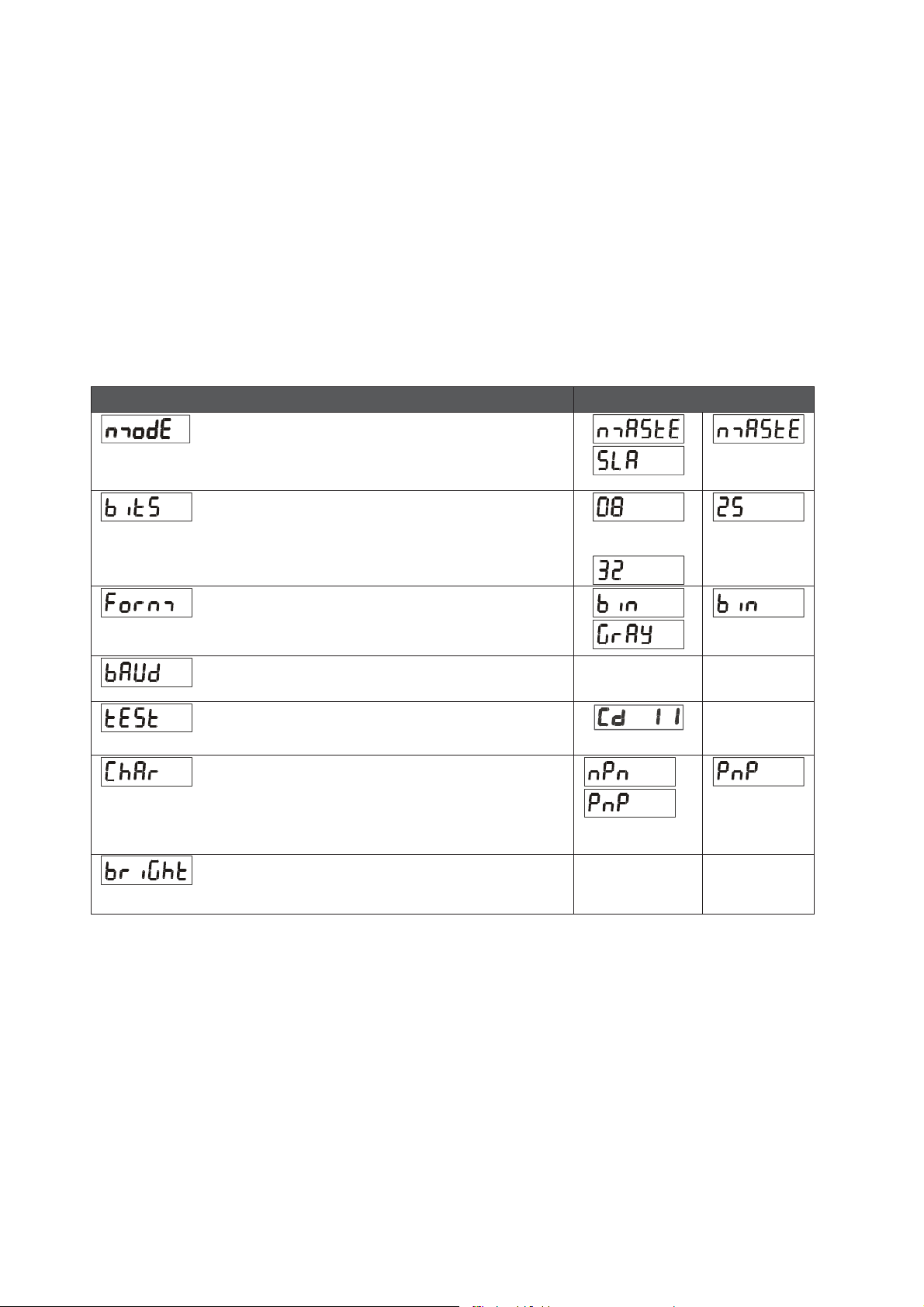
Menu
Setting Range
Default
SSI--Mode
Setting of Master Mode or Slave Mode
For details see section 5.1
SSI--Bits
Bit length of the SSI string
For more details see section 5.2 .....
SSI--Format:
Setting of the SSI code (Binary or Gray)
SSI--Baud Rate
0.1 ... 1000.9
kHz
100.0
k
kHz
SSI Test
SSI Self test functions (see 5.5.)
etc.
Characteristics *)
Switching characteristics of the Reset input
NPN: switch to "-" *)
PNP: switch to "+"
Brightness
20%, 40%, 60%
80% and 100%
100%
Brightness of the 7-segment LED display
*) Please observe hints given in chapter 1.3
$8?EPDFÏÏV Page 14 / 43
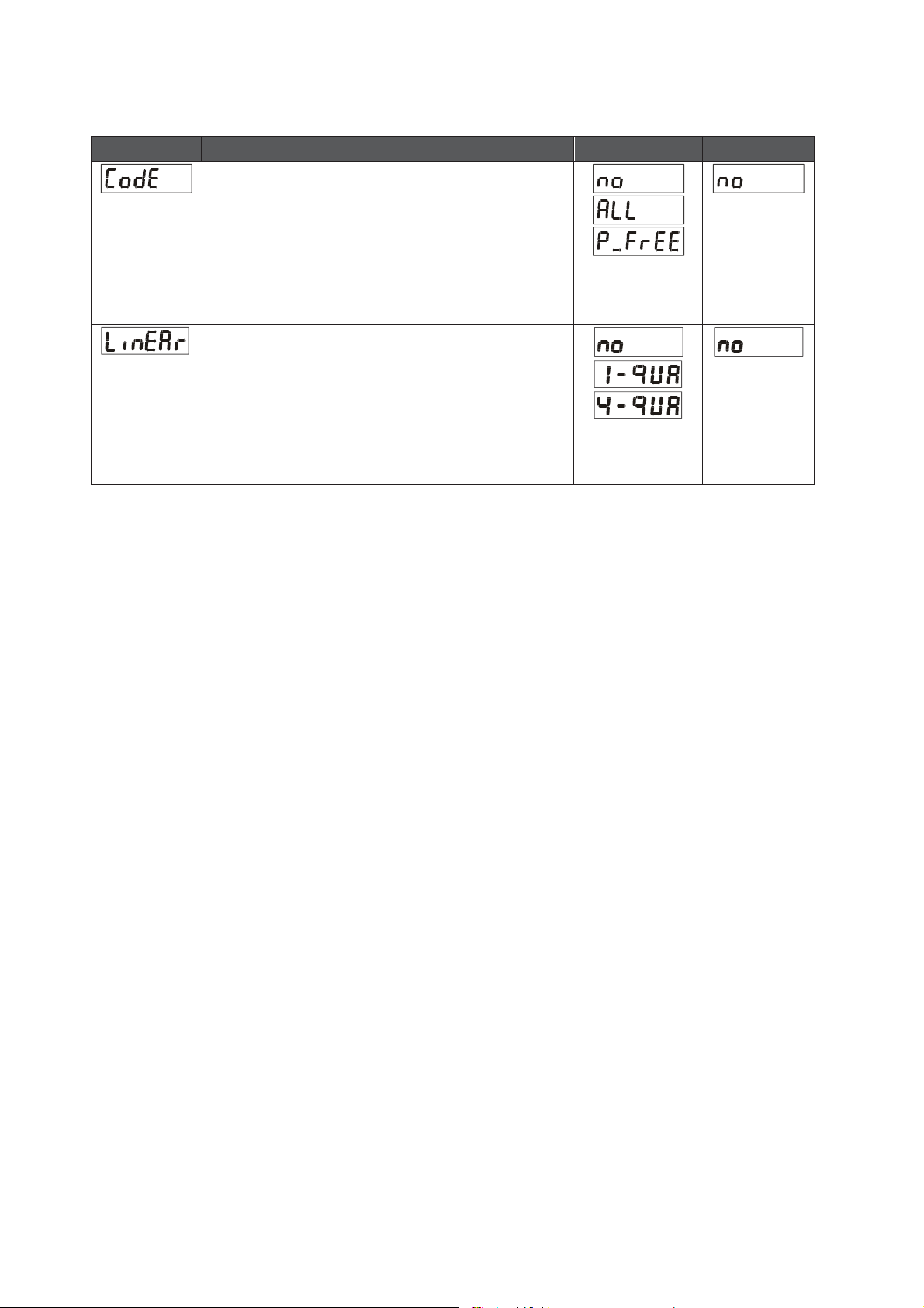
MMenu
SSetting Range
DDefault
Code Locking
Interlock of keypad access (see 2.5)
no:
Keypad accessible at any time
All:
Keypad interlock for all functions
P-Free:
Keypad interlock except for PreselectionÏ
Settings Pres 1 und Pres 2 (model $)
Linearization Mode
For details please see 6.1 und 6.2.
no:
Linearization is switched OFF *)
1
-qua:
Linearization settings for the positive range
only (negative values will appear as a mirror).
4--qua:
Linearization over the full numeric range
*) The menu will not display any further linearization parameters

$8?EPDFÏÏV Page 15 / 43
4
4.2. Operational Parameters
Menu
Setting Range
Default
M--Factor *):
Multiplying factor for the SSI value
(after consideration of possible bit blanking)
-9.999 … 9.999
1.000
D--Factor *):
Dividing factor for the SSI value
(after consideration of possible bit blanking)
0.001 … 9.999
1.000
P--Factor *):
This signed value will be added to the SSI result
(after consideration of possible bit blanking)
-199999
…
999999
0
Decimal Point
Setting according to the decimal formats shown in
the display
000000
00000.0
...
0.00000
00000.0
Display:
Display mode of the unit
norm:
regular scaling of the display
359.59:
Angular display format 359° 59' with use of
the Round Loop Function
norm
359.59
norm
Hi Bit **):
1 … 32
25
Bit Blanking Function: Defines the highest bit for
evaluation. To evaluate all encoder bits this
parameter has to be set to the total number of bits
according to setting
Lo Bit **):
1 … 31
1
Bit Blanking Function: Defines the lowest bit for
evaluation. To evaluate all encoder bits this
parameter has to be set to "01"
*) Scaling details are explained under 5.3
**) For more details about Bit Blanking see 5.2

$8?EPDFÏÏV Page 16 / 43
MMenu
SSetting Range
DDefault
Direction
Parameter to negate the SSI value, resulting in
reversal of the direction of the encoder count.
riGht:
ascending values with forward motion
LEFt::
decreasing values with forward motion
riGht
LEFt
riGht
Error: (please refer to 5.6)
Defines the control of presence of an encoder and
the location of the Error Bit in case of error.
00:
No error bit available
Control of presence of an encoder is off
01:
No error bit available
Control of presence of an encoder is on
>01:
Location of the error bit
Control of presence of an encoder is on
0 ... 32
0
Error--Polarity *):
Defines the polarity of the Error Bit in case of error.
0
0:
Error Bit is Low in case of error
1: Error bit is High in case of error
0
1
0
When an error occurs, „
„Err-b“
appears on the display.
The same function can also be used to monitor the Power Failure Bit of an encoder
(mostly called „PFB“).
Round Loop
Defines the number of encoder steps per revolution
with use of the Round Loop Function (see 5.4.2).
0:
Normal display of the encoder data, no
Round Loop Function
>0:
Number of steps per Round Loop Cycle
0 ... 999999
0
Time
Sets the update cycle of the display (and of the
analogue output or the switching outputs where
applicable). The fastest possible update time is
3 msec. respectively one telegram length including 4
pause clocks. With Slave operation the next update
will occur when the unit synchronizes again to the
Master pause following to the expiration of the
update time.
0.000 ... 1.009
sec
0.01 sec

$8?EPDFÏÏV Page 17 / 43
MMenu
SSetting Range
DDefault
Reset
A Reset command is available to store the actual SSI
position to register „Zero Position“. As a result, the
display value will become zero at the actual encoder
position, and all further operation will refer to this
new datum point. The zero position remains
memorized also after power-down.
no:
Reset function disabled
Front:
Reset function by the front SET key
E_tErn:
Reset function by the remote Reset input
FR u E:
Reset via key and remote input
Zero Position: *)
Defines the zero position of the display. When you
set this parameter to e.g. "1024", the unit will
display zero when the encoder position is 1024.
Zero Position can be set directly via keypad or by
means of an external Reset command.
-199999
...
999999
0
P01_X **)
Linearization Point 1_X
X value of the first interpolation point.
-199999
... 999999
999999
P01_Y
Linearization Point 1_Y
Y value of the first interpolation point.
-199999
... 999999
999999
…
P16_X
Linearization Point 16_X
X value of the 16. interpolation point.
-199999
... 999999
999999
P16_Y
Linearization Point 16_Y
Y value of the 16. interpolation point.
-199999
... 999999
999999
*) Please observe that Parameter P_Fac will cause an additional displacement of the zero position
**) Parameters P01_X to P16_Y appear only when the linearization has been enabled in the basic menu

$8?EPDFÏÏV Page 18 / 43
4
4.3. Additional Parameters for the Analogue Output
(model
$
The following additional settings for the analogue output appear in the Basic Menu:
Menu
Setting Range
Default
Analogue Characteristics
You can set the following output options:
+/- 10 V (bipolar),
0 - 10 V (positive only),
4 - 20 mA
0 - 20 mA.
With setting +/-10 Volts the polarity of the output
voltage will follow the sign in the display
Analogue Offset:
Set this parameter to 0 when you expect your
analogue signal to start with 0 V (or 0 mA / 4 mA
respectively). Where another zero definition is
desired it can be set by this parameter. Setting of
e.g. 5.000 will already produce 5 volts with the
output in zero state.
-9,999..+9,999
0,000
Analogue Gain:
Parameter to set the analogue output swing. Setting
10.00 will allow full swing of 10 V or 20 mA, setting
8.00 will reduce the swing to 8 V or 16 mA.
00,00..99,99
10,00
The following Operational Parameters provide scaling of the analogue output:
Menu
Setting Range
Default
Analogue--Begin
Start value of the analogue conversion range
-199999...999999
0
Analogue--End
End value of the analogue conversion range
-199999...999999
100000
By means of these two parameters any window of the whole display range can be mapped onto
the analogue output.

$8?EPDFÏÏV Page 19 / 43
The subsequent example shows how to convert the display range from 1400 to 2000 into an
analogue signal of 2 - 10 volts.
66,'LVSOD\9DOXH
9ROWV
$QDORJXH2XWSXW
A--ChAr = 0 --110 V
AnAbEG = 1400
OFFSEt ==2.000
AnAEnd ==2000
GAin = 8.00
All settings refer t
o the scaled values shown in the display of the unit,
and not to the original SSI encoder data

$8?EPDFÏÏV Page 20 / 43
4
4.4. Additional Parameters for Preselections and Switching Outputs
(model
$
The following additional settings for the Preselections appear in the Basic Menu:
Menu
Default
Switching Characteristics of Output 1
Greater/Equal. Output to switch statically ON
when Display Value
Preselection1
Lower/Equal. Output to switch statically ON
when Display Value Preselection1
Greater/Equal. Output to switch dynamically ON
when Display Value
Preselection1
(timed output pulse) *)
Lower/Equal. Output to switch dynamically ON
when Display Value
Preselection1
(timed output pulse) *)
Switching Characteristics of Output 2
See above, but Preselection2
See above, but Preselection2
See above, but Preselection2
See above, but Preselection2
Output to switch statically ON when
Display Value Preselection1 – Preselection2
**)
Output to switch dynamically ON when
Display Value Preselection1 – Preselection2
**)
HYSt 1
Hysteresis 1
Adjustable hysteresis for output 1
Setting range 0 ... 99999 display units
0
HYSt 2
Hysteresis 2
Adjustable hysteresis for output 2
Setting range 0 ... 99999 display units
0
*) Timed output pulses have a fixed duration of 500 msec (factory adjustable only)
**) Trailing Preset to generate an anticipation signal with a fixed distance to the main signal
This manual suits for next models
4
Table of contents
Other Hein Lanz Measuring Instrument manuals

Popular Measuring Instrument manuals by other brands
 Manual and Configuration")
enertexbayern
enertexbayern Enertex KNX Smartmeter 85A (RT) Manual and Configuration

ABQINDUSTRIAL
ABQINDUSTRIAL HORIBA U-50 Series instruction manual

Ono Sokki
Ono Sokki DS 0297 manual

Blackline Safety
Blackline Safety G6 Dock Technical user's manual

CCL ELECTRONICS
CCL ELECTRONICS C8437 user manual

Tek-Trol
Tek-Trol Tek-Flux 1400A instruction manual


