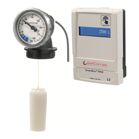
Self Climat Smartbox MINI User manual

SmartBox®MINI
Artikel-Nr. 308 051
Assembly and operating instructions
Smartbox®MINI
electronic remote level gauge for unpressurized tanks
mechanical level
gauge type FSA-E digital display unit
CONTENTS
ABOUT THESE INSTRUCTIONS........................................................................................................... 14
SAFETY ADVICE................................................................................................................................... 14
ADDITIONAL SAFETY ADVICE............................................................................................................. 14
PRODUCT-RELATED SAFETY ADVICE ............................................................................................... 15
GENERALLY.......................................................................................................................................... 1
DESIGN................................................................................................................................................. 1
INTENDED USE .................................................................................................................................... 1
FUNCTION DESCRIPTION ................................................................................................................... 1
CONNECTIONS.....................................................................................................................................
START-UP.............................................................................................................................................
PROGRAMMING................................................................................................................................... 22
INSTALLING THE SMARTBOX MINI..................................................................................................... 2
TROUBLESHOOTING........................................................................................................................... 2
REPAIRS............................................................................................................................................... 2
MAINTENANCE..................................................................................................................................... 2
SHUT-DOWN......................................................................................................................................... 2
DISPOSAL............................................................................................................................................. 2
WARRANTY .......................................................................................................................................... 2
TECHNICAL CHANGES ........................................................................................................................ 2
TECHNICAL DATA ................................................................................................................................ 2
13/72

SmartBox®MINI
Artikel-Nr. 308 051
ABOUT THESE INSTRUCTIONS
xThese instructions explain how to install and operate the SmartBox
®
MINI
digital display unit.
xSeparate installation and operating instructions are available for the
mechanical level gauge type FSA-E.
xThese instructions are part of the product.
xKeep them in a safe place while you are using the product.
xThese instructions must be observed and handed over to the operator to
ensure that the component operates as intended and to comply with the
warranty terms.
xIn addition to these instructions, please observe national regulations, laws and
installation guidelines.
NOTE
Observe the installation and operating instructions for "FSA-E level gauge" part no.
15 276 50.
SAFETY ADVICE
DANGER
describes a personal hazard with a high degree of risk.
«May result in death or serious injury.
WARNING
describes a personal hazard with a medium degree of risk.
«May result in death or serious injury.
CAUTION
describes a personal hazard with a low degree of risk.
«May result in minor or moderate injury.
ADDITIONAL SAFETY ADVICE
NOTICE
describes material damage.
«Has an effect on ongoing operation.
NOTE
describes general information.
PRODUCT-RELATED SAFETY ADVICE
DANGER
May not be used in explosion-prone areas.
May cause an explosion or fatal injuries.
Must be installed by a specialist company in accordance with local industrial
health and safety regulations.
Installation outside the defined ex zone.
14/72

SmartBox®MINI
Artikel-Nr. 308 051
GENERALLY
SmartBox®MINI is an electronic remote level gauge for unpressurised tanks, consisting of a
digital display unit with electronic interface for the mechanical FSA-E level gauge, simply
referred to as FSA-E below.
By touching the sensor depending on your settings, the display shows the
contents in the tank in litres, percentage by volume or as filling height in
centimetres for a few seconds.
The measurement data is output in a 16-character, single-row LCD display on the digital
display unit.
The scale of the FSA-E, which is mounted directly on the tank, also shows the level in the
tank continuously in centimetres.
The FSA-E 0 – 160 cm is suitable for all unpressurised tanks to a level of 150 cm, for levels
up to 240 cm, use the FSA-E 0 – 250 cm.
NOTE
TheSmartBox®MINI is rated as Protection Class IP30 and is approved for indoor use
only.
The indicated measurements are not gauged for invoicing.
DESIGN
Design of the digital display unit
Housing top
Sensor
Display
Bottom part of housing
Connection cable
Clip-on ferrite core
15/72

SmartBox®MINI
Artikel-Nr. 308 051
INTENDED USE
NOTE
Intended use in the operating media refers to the level gauge type FSA-E.
Operating media
xFuel oil
xFuel oil Bio
xDiesel fuel
xFAME
xVegetable oil
xWaste oil
xOther water-hazardous, non-flammable liquids
xRainwater
xUrea solution
NOTE
You will find a list of operating media with descriptions,
the relevant standards and the country in which they are used at
www.gok-online.de/en/downloads/technical dokumentation/
list of operating mediums.
Other media on request!
Place of operation
xNot suitable for outdoor use.
FUNCTION DESCRIPTION
The content of the tank is determined by measuring the level on the basis of the float
principle. With an electronic interface, the measurement from the FSA-E is sent via a
connection cable to the SmartBox®MINI digital display unit, where it is converted into the set
output value and shown on the display.
Installation example - standard installation of SmartBox®MINI
The FSA-E with electronic interface is set to
the maximum permitted level and is installed
in an existing G 1 1/2 tank connection
opening.
The FSA-E with electronic interface is
connected to the digital display unit with a
10 m cable or a suitable extension cable up
to a distance of 50 metres (see cable
extension option).
16/72

SmartBox®MINI
Artikel-Nr. 308 051
CONNECTIONS
Connecting the cable to the digital display unit
NOTE
With the power disconnected, remove the top of the housing to connect the cable.
Connect the cable to the digital display unit:
xCarefully pierce the white membrane to feed the cable through.
xInsert the connection cable through the cable opening on the bottom part of the housing.
xConnect the coloured cable cores according to the terminal assignment.
Terminal assignment from left to right:
1
ws = White 2
bn = Brown 3
gn = Green 4
gb = Yellow 5
gr = Grey
Connecting the cable:
xDepress the spring clamp with a suitable screwdriver.
xInsert the coloured cable cores into the openings of the terminal block.
xRelease the spring clamp.
xCheck that the connection is firm. Assemble the cable relief.
xPosition the clip-on ferrite core near the housing.
xInsert the batteries in the battery compartment of the digital display unit.
NOTICE
Malfunction if cable is touched when live.
Permanent damage to the digital display unit cannot be ruled out.
Insert the batteries only after you have connected the cable.
NOTICE
Malfunction as a result of incorrect wiring.
The proper function is no longer guaranteed.
Check the terminal assignment.
Cable extension/wall duct options
NOTE
Recommended cable extension with a LIYY cable, cable cross-section
5 x 0.25 mm2; cable diameter 4.5 to 6 mm (up to 50 m extension possible).
Extend the connection cable and/or pass through a wall:
xRemove the clip-on ferrite core
from the cable.
xExtend the connection cable or pass it through a wall.
xReplace the clip-on ferrite core on the cable.
xConnect the cable to the digital display unit (see above).
xPosition the clip-on ferrite core near the housing.
17/72

SmartBox®MINI
Artikel-Nr. 308 051
START-UP
Operating elements and screen of the digital display unit
The device is adjusted once when it is put into operation. The digital display unit is put into
operation after the cable has been connected and the batteries have been inserted.
When it has been started, the digital display unit works in display mode. The readings are
shown in a 1-line LCD display with 16 characters. The display has background lighting so that
the readings can be seen in all lighting conditions.
View of the digital display circuit board
Activate the display on the
sensor bar
The parameters are adjusted
with three small push-
buttons:
MINUS ENTER PLUS
SW6 SW4 SW5
These are located on the
circuit board above the
terminal block.
Terminal assignment from left to right:
1
ws = White 2
bn = Brown 3
gn = Green 4
gb = Yellow 5
gr = Grey
Setting a
parameter: Press [Enter] to open setup mode.
Select the desired setting parameter via PLUS [+].
Press [Enter] to call up the value selection for the parameter.
Set the value with MINUS [-] / PLUS [+], press [Enter] to save.
Quitting the
setup mode: You can quit the setup mode at any time.
Select “Exit“ and press [Enter]
«to go back to the standard display mode.
Programming 1st steps
1. Touch the sensor bar to activate the display.
2. The 1st menu item "Unit" is displayed.
18/72

SmartBox®MINI
Artikel-Nr. 308 051
PROGRAMMING
Before programming, determine the required tank data.
Unit Set
Null Sensor
Type maximum
Height maximum
Volume Tank-
shape Disp
lay
Type
Litres Only
when
the
FSA-E
is
ready
to
"Set
Null"
250cm
FSA-E max H=
0cm to
150cm
or
240cm
max V=
0L to
999999L
Linear On
Touch
Height 160cm
FSA-E Cylinder
Perma
nent
Percent Ball Exit
Oval
Click to confirm
the selected values
ÆOK.
Convex
Concave
At maximum height and
maximum volume, the
values are set with
or .
Cylinder
>50000L
Steel
Tank
19/72

SmartBox®MINI
Artikel-Nr. 308 051
NOTE
You can enter the parameters before the "Set Null" zero offset adjustment between
the digital display unit and the FSA-E or also after "Set Null".
Factory settings
Menu item Default parameters
Unit Litre
Sensor Type 250 cm FSA-E
maximum Height 250 cm
maximum Volume 2500 L
Tank shape Linear
Display Type OnTouch
Menu item Entry function Entry value
Unit Choice of display unit
Litre Select a setting and confirm with [Enter].
Ok is displayed.
Display in litres
Percent Display volume in %
Height Display level in cm
Set Null Zero offset adjustment between the digital
display unit and the FSA-E Adjustment with
"Set Null"
Sensor Type Enter the measuring range
250 cm FSA-E Select a setting and confirm with [Enter].
Ok is displayed. 0 - 250
160 cm FSA-E 0 - 160
maximum
Height Enter the maximum internal height of the
tank
(height without dome)
250 cm FSA-E Enter with (+)/(-) and press [Enter] to confirm.
Ok is displayed. 0D[+FP
160 cm FSA-E 0D[+FP
maximum
Volume Enter the tank volume
Enter with (+)/(-) and press [Enter] to confirm.
Ok is displayed. 0D[9/
NOTE
If the selection of the sensor type changes, you have to re-enter this and the
maximum tank height.
20/72

SmartBox®MINI
Artikel-Nr. 308 051
Menu step Entry function Entry value
Tank shape Choice of tank shape
Linear linear tank; rectangular tank; vertical cylinder; steel tank
welded together in the basement
Cylinder cylindrical tank to 50 m³ (see also alternative
Cyl. > 50000 L) horizontal cylinder; tube-shaped tank;
typical design as outdoor tank or underground steel tank
Ball spherical tank
underground, spherical tank; often a plastic (GRP)
underground tank
Oval oval tank in basement
typical design of GRP tanks and single-walled sheet
metal tanks
Convex plastic battery tank, convex
slightly convex shape, alternative to linear
Concave plastic battery tank, concave
slightly concave shape, alternative to linear
Cylinder
> 50000 L cylindrical largHRXWGRRUWDQNޓPñޓ/WR
100000 L
Steel Tank Sheet steel tank or tank battery
Straight side walls with semicircular dome at top and
bottom
Display Type Set the display
OnTouch Select a setting and confirm with [Enter].
Ok is displayed. Value is displayed for a short time. Sleep mode
Permanent Select a setting and confirm with [Enter].
Ok is displayed. Continuous display. Continuous
display, sensor
not in operation
Exit Programming completed
NOTE
Display type "Permanent" is recommended only for short times during battery
operation.
NOTE
After programming, the digital display is ready for "Set Null", the zero offset
adjustment with the FSA-E.
21/72

SmartBox®MINI
Artikel-Nr. 308 051
INSTALLING THE SMARTBOX MINI
Before installation, check that the product is complete and has not suffered any damage
during transport.
ASSEMBLY, START-UP and MAINTENANCE are to be carried out by a specialised
company in terms of water law.
For the system to function as intended it must be installed professionally in compliance with
the technical instructions applicable to the planning, construction and operation of the entire
system.
These regulations also include the accident prevention regulations of the employers’ liability
insurance associations, the VDE regulations, and the installation and operating instructions.
Installation instructions
The display unit has a wall installation housing and is operated with the top of the housing
closed. Installation and start-up by a specialised installer is carried out with the display unit
open.
Installation of the digital display unit
1. Loosen the screw on the bottom of the digital display unit and remove the top of the
housing.
2. Place the digital display unit on a suitable position on a smooth, vertical wall and pierce
the pre-cut holes on the inside back wall of the housing. Mark the points for installation.
NOTICE
Do not damage electronic components.
Use a suitable tool to pierce the openings.
3. Place the digital display unit on the marks and fix it in place using the supplied anchors
and screws.
4. Close the top of the housing and tighten the screw on the bottom of the digital display unit.
TROUBLESHOOTING
Fault cause Action
Battery warning Battery _ _%
when remaining capacity is low «Constant check
No display
Batteries empty «Replace batteries
Error code Meaning
Error 0001 No contact with FSA-E
Check the connection between the magnetic sensor
and the magnetic encoder in the connection plug on
the FSA-E
Error 0002 Connection cable on the digital display unit not connected
Connect the cable
22/72

SmartBox®MINI
Artikel-Nr. 308 051
REPAIRS
If the measures explained above under TROUBLESHOOTING do not result in regular
START-UP, and if there is no dimensioning problem, the product must be sent to the
manufacturer for a check. Our warranty does not apply in cases of unauthorised interference.
MAINTENANCE
Replacing the batteries
1. Loosen the screw on the top of the housing, remove empty batteries from the display unit
and insert new batteries (3 x AA 1.5V batteries) paying attention to the "+" and "-" poles.
2. Replace the top and tighten the screw.
NOTE
Stored data is not lost when you replace the batteries.
SHUT-DOWN
Pay attention to the following when you take the digital display unit out of service:
NOTICE
Damage to device from leaking batteries
Can damage the device.
If the digital display device will not be used for some time, remove the batteries.
NOTE
Stored data is not lost when you take the device out of service.
DISPOSAL
To protect the environment, our products may not be disposed of along with
household waste.
The product must be disposed of via a local collection station or a recycling station.
Discharged batteries should be deposited at collection stations or in shops with
collection facilities. Stored data is not lost when you replace the battery.
WARRANTY
We guarantee that the product will function as intended and will not leak during the legally
specified period. The warranty term begins when the product is handed over to the customer.
The scope of our warranty is based on Section 8 of our Terms and conditions of delivery and
payment.
TECHNICAL CHANGES
All the information contained in these installation and operation instructions is the result of
product testing and corresponds to the level of knowledge at the time of testing and the
relevant legislation and standards at the time of issue.
We reserve the right to make technical changes without prior notice. Errors and omissions
excepted.
All figures are for illustration purposes only and may differ from actual designs.
23/72

SmartBox®MINI
Artikel-Nr. 308 051
TECHNICAL DATA
SmartBox
®
MINI digital display unit
Supply voltage 3 batteries, AA, 1.5V
Dimensions H/W/D in mm 144 x 99 x 45
LCD display 16 characters / 1-line
Accuracy +/- 2 % of upper range value
Measuring range
FSA-E0 - 160 cm Level
0 to 150 cm
Measuring range
FSA-E0 - 250 cm Level
0 to 240 cm
Ambient temperature 0°C to +50°C
Housing material ABS / PC
Type of protection IP30 acc. to EN 60529
Notes for required tank data
Menu step Entry function Entry value
Sensor Type 250 cm FSA-E R
R
160 cm FSA-E
R
R
maximum Height 9DOXH0D[+FP _ _ _ cm
9DOXH0D[+FP _ _ _ cm
maximum Volume 0D[9/ _ _ _ _ _ _L
Tank shape Linear R
R
Cylinder to 50 m³ R
R
Ball R
R
Oval R
R
Convex R
R
Concave R
R
&\OLQGHUޓPñ R
R
Steel Tank R
R
24/72
Table of contents
Other Self Climat Measuring Instrument manuals
