HEIN-WERNER AUTOMOTIVE HW93692 Instructions for use

Operating Instructions & Parts Manual
SFA Companies ©2004
10939 N. PomonaAve. Kansas City, MO 64153
816-891-6390
Model Number Capacity
HW93692 7 Ton
AirOperated End Lift
Made in
North America
-Before using this product, read this manual and follow all its Safety Rules and Operating Instructions
HW93692-M0
Warranty P2
Save These Instructions P3
Product Description P3
Specifications & Safety Instructions P3
Assembly P4
Operation P5
Maintenance P6
Troubleshooting P6
Replacement Parts P6
TWO YEAR LIMITED WARRANTY
Fora periodof two(2) yearsfrom dateof purchase,SFA Companieswill repair or replace, atits option,without charge,any
of its products which fails due to a defect in material or workmanship, or which fails to conform to any implied warranty not
excludedhereby.
Performance of any obligation under this warranty may be obtained by returning the warranted product, freight prepaid, to
SFA Companies WarrantyService Department,10939 N. PomonaAve., Kansas City,MO 64153.
Except where such limitations and exclusions are specifically prohibited by applicable law:
(1)THECONSUMER'SSOLEANDEXCLUSIVEREMEDYSHALLBETHEREPAIRORREPLACEMENT OF DEFECTIVE
PRODUCTSAS DESCRIBEDABOVE.
(2) SFACOMPANIESSHALLNOTBELIABLEFORANYCONSEQUENTIALORINCIDENTALDAMAGEORLOSSWHAT-
SOEVER.
(3)THEDURATION OFANYANDALLEXPRESSEDANDIMPLIEDWARRANTIES, INCLUDING WITHOUT LIMITATION,
ANYWARRANTIESOFMERCHANTABILITYANDFITNESS FORA PARTICULARPURPOSE,ISLIMITED TOAPERIOD
OF TWO (2) YEARS FROM DATE OF PURCHASE.
Some states do not allow limitations on how long an implied warranty lasts, so the above limitation may not apply to you.
Some states do not allow the exclusion or limitation of incidental or consequential damages, so the above limitation or
exclusionmay not applyto you. Thiswarranty gives youspecific legalrights, and youmay also haveother rightswhich vary
from state to state. 2
TABLE OF CONTENTS
HW93692-M0
SAVE THESE INSTRUCTIONS
Foryour safety, read,understand,and follow the information providedwith andon thisjack. Theowner and operator of this
equipmentshallhavean understanding ofthisjackand safe operatingproceduresbeforeattempting to use.Theownerand
operatorshallbe awarethat use andrepair of thisproduct mayrequirespecial skillsand knowledge. Instructionsand safety
informationshall beconveyed in the operator's nativelanguage before use of this jack isauthorized. If any doubt exists as
tothe safe and proper use of this jack, remove from serviceimmediately.
Inspect before each use. Donot use if there are broken, bent,cracked, ordamaged parts(including labels). Anyjackthat
appears damaged in any way, operates abnormally or is missing parts, shall be removed from service immediately. If the
jack has been or suspected to have been subjected to a shock load (a load dropped suddenly, unexpectedly upon it),
immediately discontinue to use until jack has been inspected by a Hein-Werner authorized service center. It is recom-
mended that an annual inspection be done by qualified personnel. Labels and Operator's Manual are available from
manufacturer.
PRODUCT DESCRIPTION
TheHein-WernerAir OperatedEnd Liftis designed tolift, but notsustain, ratedcapacity loads. Thedual hydraulicdampers
providesafetyrestraintifloadis suddenly removed. Intended use: To engagethemetalbumperofavehicleandraiseforthe
purposeof serviceand/or repairof vehiclecomponents.Afterlifting, loads must be immediatelysupported byappropriately
ratedjack stands.Check vehicle'sfactory serviceand/or repair manual for proper lift points.
DO NOT USE TO DOLLY OR MOVE VEHICLE. DO NOT USE FOR ANY PURPOSE OTHER THAN THOSE USES
OUTLINED ABOVE !
3
SAFETY INSTRUCTIONS
BEFORE USE
1.Verify thatthe product and the application are compatible,if in doubt call Hein-Werner Technical Service(816)891-6390.
2. Read this manual completely and familiarize yourself thoroughly with the product, its components and recognize the
potential hazards associated with its misuse before using this product.
3.Ensure thatjack rolls freely, the air cylinder andcontrol valve operates smoothly, raises and lowers the unloaded saddle
throughoutthe lift range before putting into service.
4. Loosen air vent screws (upper screws) on each hydraulic damper located on side of air cylinders.
5. Ensure the jack is loaded on center with the saddles placed equal distance from the center.
6. Replace worn or damaged parts and assemblies with Hein-Werner Replacement Parts only. (See Replacement Parts
Section). Lubricate as instructed in Maintenance Section.
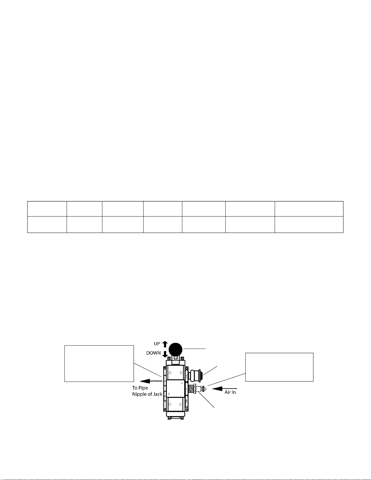
7. Connect lift control valve as shown in Figure 1. Connect air nipple to air input port before connecting air hose.
Note:Use only NPTthread sizeair nipple. Tightensecurely toprevent accidental removalof componentswhile in use.Take
care not to introduce compound into port orifices.
SPECIFICATIONS
Capacity
58-1/2"
Model Min. Height Max. Height
13-1/2"
HW93692 7Ton
PowerRaise
32-1/2"
SaddleSpread Min. PSI for Rated Load
29" to 41" 200
Figure 1. Lift Control Valve Illustration
Control Knob
Air Filter
1/4" NPT Air Nipple (not provided)
Step 1:
Threadliftcontrolvalvein
clockwise direction onto
the pipe nipple of jack
Step 2:
Connect air hose to 1/4"
NPTAirNipple
HW93692-M0
• Study, understand, and follow all instructions
provided with and on this device before operating this
device.
• Do not exceed rated capacity.
• This is a lifting device only.
• Center load on saddle.
•Never lift vehiclewhich cannot rollfreely forward and
backwardduring lift.
• After lifting, immediately transfer the load to
appropriately rated vehicle stands.
• Never work on, under, or around a load supported by
this device.
• Use only on hard, level surfaces capable of
sustaining rated capacity loads.
• Do not move or dolly loads with this device.
• Do not modify this device.
• Do not use adapters or accessories that are not
provided initially.
• Lift only on areas of the vehicle as specified by the
vehiclemanufacturer.
• Failure to heed these markings may result in
personal injury and/or property damage.
• Leer, comprender, y seguir las instrucciónes antes
de utilizar el aparato.
• El manual de instrucciónes y la información de
seguridaddeben estar comunicado en lengua del
operadorantes del uso.
• No seguir estas indicaciónes puede causar daños
personaleso materiales.
!WARNING
ASSEMBLY
Little, if any, assembly is required of this jack.Make sure lift control valve is secured into the pipe nipple of the jack.
Familiarize yourself with the illustrations in the operator's manual. Know your jack and how it operates before attempting
to use.
4
!WARNING
Toavoid crushing and related injuries:
NEVERwork on,under oraround aload supported
only by a jack. Immediately transfer the load to
adequately rated jack stands.
!ADVERTENCIA
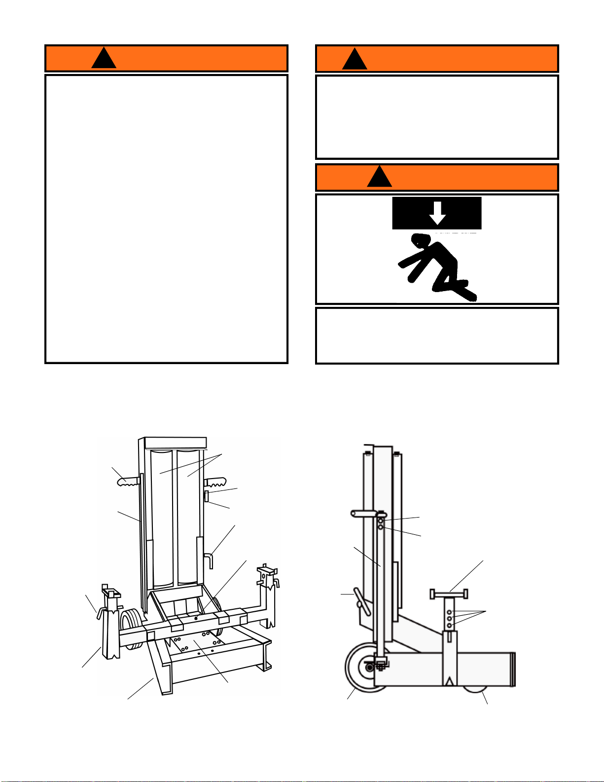
Air Cylinders
Handle Bar Grip
Position Pin
Base Section
Lifting Beam Bumper Bolt
(Underneath the
lifting beam)
Lift Control Valve
Locking
Pin
Figure2.AirOperatedEnd Lift Components
SafetyBar
Level
Figure3.Air Operated EndLift Components(side view)
Saddle Height
Adjustment
Holes
Saddle
Rear Wheel Caster
Air Vent Screw (1 per damper)
Oil Filler Screw (1 per damper)
Hydraulic Damper
(1 per air cylinder)
Hydraulic
Damper
Safety
Bar
Pipe Nipple
(not shown)
HW93692-M0

OPERATION
Lifting
1. Ensure that the vehicle is on a flat, hard and level surface and is free to roll forward and backward during the lift.
2. Connect 1/4" NPT air nipple and air hose to lift control valve air inlet port. (See Figure 1 on page 3)
3. Loosen air vent screws (upper screws) on each hydraulic damper located on side of air cylinders.
4. Insert lifting beams fully to engage lock. For low pickup height, rotate the beams 180 degrees.
5. To adjust the location of the lifting beams, push the locking pin upward from underneath and pull out the lifting beams.
(seeFigure 4)
6. Adjust bumper bolt to increase ground clearance. (see Figure 2 on page 4)
7.Make sure both saddles are positioned directlyunder the vehicle manufacturer's recommendedlift points.
8. To raise jack, slowly press the lift control valve lever toward the position marked "UP" until saddles contact with the lift
point.!STOP! RELEASE GRIP ON THE LIFT CONTROL VALVE! Confirmthat the saddlesare positioned correctly,then
continue to press the lever until load reaches desired height. Simply release the lever to stop.
9. Transfer the load immediately to appropriately rated jack stands.
Lowering
1. Raise load high enough to clear the jack stands, then carefully remove jack stands (always used in pairs).
2. Slowly lower the load by disengaging safety bar* and press lift control valve lever "DOWN".
* To disengage safety bar: Push safety bar lever towards front end of the jack. (see Figure 5)
Note: RefertoTable 1for forair pressure rating for different load application
5
!WARNING
To reduce the risk of personal injury and property
damage, NEVER extendliftingbeams beyond
locked position
AIR PRESSURE
PSI LOAD
(LBS)
200 14,000
180 12,000
160 11,000
140 9,500
120 8,000
Table 1. Recommended Air Pressure for Different Load
Application
Figure4.
RetainingBars Locking Pin
LiftingBeams
Figure5.Air OperatedEnd LiftComponents (rear view)
SafetyBar
Lever Stopper
Be sure all tools and personnel are clear before
lowering load. Only attachments and/or adapters
supplied by the manufacturer shall be used. Lift
only on areas of the vehicle as specified by the
vehiclemanufacturer.
! Safety Messages !
HW93692-M0

6
REPLACEMENT PARTS
Not all components of the jack are replacement items, but are illustrated as a convenient reference of location and
position in the assembly sequence. When ordering parts, give Model number, parts number and description on page 7.
Callorwrite forcurrent pricing: Phone:(816)891-6390or contact Hein-Werner Customer Support,
MAINTENANCE
1. Lubricate all moving parts with oil/grease.
2. Fill the hydraulic damper with 10W40 motor oil only. Fill the oil through the lowest hole located on the hydraulic damper
when jack is fully lowered.
Important: Useonly 10W40motor oil.Avoid mixingdifferent types of fluid and Never usebrake fluid,turbine oil, transmis-
sion fluid, or glycerin.
3. Fill with oil until level with the oil filler screw hole. Reinstall the oil filler screw.
Lubrication
A periodic coating of light lubricating oil to pivot points, axles and hinges will help to prevent rust and assure
that wheels, and caster assemblies move freely.
Storage
When not in use, store the jack with cylinder fully lowered.
TROUBLESHOOTING
PossibleCauses Corrective Action
Jack will not lift load •Air pressure too low
• Air hose kinked or plugged
•Air hose inner diameter too
small
• Air cylinder / components
damaged
• 200 psi minimum air pressure required to lift
ratedload
•Remove kinks andobstruction from air hose
•Consult air compressormanufacturer for the
correct size of hose
•ContactHein-Werner repair center
Jackwill notlower after unloading
Symptom
•Liftcontrolvalveimproperly
assembled and / or attached
•Safety bar engaged
• Structural damage to jack assy
•Assemble as shown in Figure 1on page 3
• Press lift control valve to raise jack slightly,
thendisengage safety bar
•ContactHein-Werner repair center
Jack raises or lowers with jerky
motion • Cylinder need lubrication •Apply #630-AAA LUBRIPLATE to cylinder
wall
HW93692-M0

7
Item no.
Part no. Qty. Description
Item no.
Part no. Qty. Description
Item no.
Part no. Qty. Description
1200472 2Screw 26 221778 4Washer 50 227646 1Hose coupling
2201086 1Lockwasher 27 221820 2Retaining ring 51 227647 1Air hose (short)
3201789 4Lockwasher 28 *223575 2U-cup 52 227648 1Air hose (long)
4203202 1Ball 29 223707 2Spring 53 227649 2Wheel (rear)
5203272 4Nut 30 223964 3Elbow 54 227651 2Position Pin
6203273 3Nut 31 224641 2Handle Bar Grip 55 227652 1Cross Pin
7204271 2Washer 32 225254 4Lockwasher 56 227654 2Pin
8204530 2Cotter Pin 33 226228 2Bushing 57 *227655 2Slip Ring
9204543 2Cotter Pin 34 226318 2Grease Fitting 58 228061 1Positioning Bar
10 207167 1Nut 35 226503 2Roller Wheel 59 228263 1Caster
11 207169 8Nut 36 226603 1Roll Pin 60 228264 1Caster Plate
12 209746 26 Roller 37 227616 1Handle Stop 61 229456 1Skid Ring
13 209967 4Lockwasher 38 227619 2Saddle Arm 62 229869 1Bolt
14 210735 4Washer 39 227622 2Saddle 63 230438 1Bottom Cap
15 †212374 2Washer 40 227626 1Air Cylinder Ass'y (R.H.) 64 230441 1Piston Rod
16 212540 1Screw 41 227629 1Air Cylinder Ass'y (L.H.) 65 231136 2Hydraulic Damper Ass'y
17 212562 1Screw 42 227631 2Elbow 66 231138 1Cylinder Plug
18 212622 1Bolt 43 227633 1Tank Retainer 67 231139 1Damper Cylinder
19 212624 5Bolt 44 227637 1Pin 68 231141 1Piston Rod
20 212688 4Bolt 45 227638 1Spacer 69 231168 2Bolt
21 214120 2Spacer 46 227639 1Axle 70 †231241 1Quad Ring
22 †214555 2O-ring 47 227640 2Piston 71 233072 2Wheel & Busing Ass'y
23 †216258 1Pump Gland Cover 48 227643 1Safety Stop Handle 72 234844 1Washer
24 220018 3Retaining Ring 49 227644 1Safety Stop Spring 73 248799 1Lift Control Valve
25 221356 1Pipe Nipple
* Included in 240513 Repair Kit. † Included in 240512 Repair Kit for 231136 Hydraulic Damper Assembly
SERVICE PARTS
HW93692-M0

memo.
Table of contents
Other HEIN-WERNER AUTOMOTIVE Lifting System manuals


Popular Lifting System manuals by other brands


Extreme Max
Extreme Max Boat Lift Boss 3005.7216 installation instructions

AmeriGlide
AmeriGlide Infinity Curved Stair Lift installation guide

Rev-A-Shelf
Rev-A-Shelf RAS-ML Series installation instructions

Meyer
Meyer E-58H installation instructions

Invacare
Invacare Birdie user manual

EZTRUNK
EZTRUNK 1900 0072 Assembly manual


