HEK GTP 1500 User manual

USER’S MANUAL
TRANSPORT PLATFORM
8095-007C
Issue: 12-2000
This manual is assigned to :
HEK GTP 1500

GTP 1500 • 8095-007CII
© 2000, Hek Manufacturing B.V., Middelbeers, The Netherlands
Nothing contained in this publication may be copied and/or published by means of
printing, photocopying, microfilm or any other method, without prior written
permission from Hek Manufacturing B.V.
Drawings are illustrative only and do not necessarily show the design of the product on the market at any
given point of time.

IIIGTP 1500 • 8095-007C
HEK Manufacturing B.V.
Westelbeersedijk 18 P.O. Box 2
5091 SM Middelbeers 5090 AA Middelbeers
The Netherlands The Netherlands
Tel : +31(0)13 51 48 653
Fax : +31(0)13 51 48 630
www.HEK.com

GTP 1500 • 8095-007CIV

VGTP 1500 • 8095-007C
FOREWORD
FOREWORD
The HEK GTP 1500 is an extremely
compact transport platform for personnel
and material.
This manual describes the installation,
operation and maintenance of the
transport platform.
The mast, consisting of separate
elements, can be adjusted in height to
the height of the building. The mast can
be simply and safely erected, from the
platform.
The transport platform must be anchored.
The HEK GTP 1500 offers a high level of
safety. In the construction of this
transport platform, particular attention has
been paid to all safety requirements. The
drive unit, for example, has been fitted with
an motor brake. An additional fail safe
brake, which operates by applying a shaft
to both racks is fitted.
Read this manual carefully before using the transport platform.
Take all the safety precautions as described in chapter 3 into account.
To simplify transport of the machine to and
on the construction site, the HEK GTP
1500 can be equipped with transport
wheels.
Thanks to the robust and solid
construction of the transport platform,
only minimum maintenance is required.
This manual describes only the basic
machine, in the standard configuration
supplied by HEK Manufacturing B.V.

GTP 1500 • 8095-007CVI
CONTENTS
CONTENTS
FOREWORD V
CONTENTS VI
SURVEY OF ILLUSTRATIONS VII
LIST OF STANDARDS VIII
MEANING OF THE SYMBOLS USED IX
1. TECHNICAL DETAILS 1-1
1.1 General 1-1
1.2 Mast element 1-2
1.3 Dimensions GTP 1500 1-2
1.4 Electrical installation 1-3
1.5 Transport platform loading 1-4
1.6 Anchor forces 1-5
1.6.1 Anchoring to a scaffolding
system 1-6
1.6.2 Anchoring to the facade 1-8
2. COMPONENTS 2-1
2.1 General description 2-1
2.2 Protection at landing height 2-2
3. SAFETY 3-1
3.1 General 3-1
3.2 Safety prior to use 3-1
3.3 Safety in use 3-1
3.4 Safety after use 3-2
3.5 Built-in and additional safety
features 3-2
3.6 Personnel 3-3
4. TRANSPORT 4-1
4.1 Repositioning on the
construction site 4-2
5. CONTROL COMPONENTS 5-1
5.1 Power supply socket for
the drive unit 5-1
5.2 Main switch 5-1
5.3 Control box on the platform 5-2
5.4 Single phase outlet 5-3
5.5 Remote control fail safe brake 5-3
6. ASSEMBLY AND ANCHORING 6-1
6.1 Preparation for assembly 6-2
6.2 Ground support 6-3
6.3 Distance to the facade 6-4
6.4 Assembly of the transport platform 6-5
6.5 Assembly of the mast 6-6
6.6 Anchoring the masts 6-10
6.7 Lightning protection 6-14
6.8 Landing barriers 6-14
7. OPERATION 7-1
7.1 General 7-1
7.2 Preparation 7-2
7.3 Testing 7-3
7.4 Operation from the platform 7-4
7.5 Stepover to scaffolding or platform 7-5
7.6 Sliding gate 7-6
7.7 Operation in an emergency situation 7-6
7.8 Fail safe brake 7-8
7.9 Static overload device 7-8
8. DISASSEMBLY AND TRANSPORT 8-1
8.1 Transport platform without
transport set 8-3
8.2 Transport platform with
transport set 8-3
9. MAINTENANCE 9-1
9.1 General 9-1
9.2 Maintenance intervals 9-1
9.3 Motor brake 9-4
9.3.1 General 9-4
9.3.2 Operating principle 9-4
9.3.3 Maintenance 9-5
9.4 Fail safe brake 9-8
9.4.1 Fail safe brake test 9-9
9.4.2 Resetting the fail
safe brake 9-10
9.5 Testing the static overload device 9-10
10. MALFUNCTION ANALYSIS 10-1
11. MACHINE DISPOSAL 11-1
12. LIST OF KEYWORDS 12-1
1. PERIODIC INSPECTION APPENDICE 1

VIIGTP 1500 • 8095-007C
CONTENTS
SURVEY OF ILLUSTRATIONS
Fig.1-1 Dimensions X
Fig.1-2 Dimensions top 1-2
Fig.1-3 Payload distribution 1-4
Fig.1-4 Anchoring to the scaffolding system 1-6
Fig.1-5 Anchoring to the facade 1-8
Fig.1-6 Anchoring to the facade 1-9
Fig.2-1 Basic set GTP 1500 2-1
Fig.2-2 Landing barrier 2-2
Fig.4-1 Lifting point 4-1
Fig.4-2 Support points forklift truck 4-1
Fig.5-1 Drive unit power supply socket 5-1
Fig.5-2 Control box 5-2
Fig.5-3 Single phase outlet 5-3
Fig.6-1 Positioning of the ground support 6-3
Fig.6-2 Distance to the facade 6-4
Fig.6-3 Jacks 6-5
Fig.6-4 Lower striker plate 6-5
Fig.6-5 Connection to cable drum 6-7
Fig.6-6 Control box 6-7
Fig.6-7 Assembly platform 6-8
Fig.6-8 Mast guard 6-8
Fig.6-9 Red top mast element 6-9
Fig.6-10 Top striker plate 6-9
Fig.6-11 Assembly platform 6-10
Fig.6-12 Anchoring to the facade 6-13
Fig.6-13 Anchoring to the
scaffolding system 6-13
Fig.6-14 Landing striker plate 6-14
Fig.6-15 Landing barrier 6-14
Fig.7-1 Control box 7-2
Fig.7-2 Push buttons control box 7-4
Fig.7-3 Loading ramp 7-5
Fig.7-4 Landing barrier 7-5
Fig.7-5 Locking sliding gate 7-6
Fig.7-6 Brake release lever 7-6
Fig.7-7 Static overload device
warning lamp 7-8
Fig.8-1 Assembly platform 8-1
Fig.8-2 Mast guard 8-2
Fig.8-3 Rear wheel set 8-3
Fig.8-4 Rear cross-brace 8-3
Fig.8-5 Front wheel set 8-4
Fig.9-1 Motor brake 9-5
Fig.9-2 Motor brake 9-6
Fig.9-3 Plug socket 9-9
Fig.9-4 Fail safe brake drop test box 9-9
Fig.9-5 Control box 9-10

GTP 1500 • 8095-007CVIII
LIST OF STANDARDS
EC Declaration of Conformity
EC DECLARATION OF CONFORMITY
pursuant to Annex IIa of the Machine Directives 98/392/EC
We, HEK MANUFACTURING B.V.
Westelbeersedijk 18
5091 SM Middelbeers
The Netherlands
hereby declare that, on the basis of its design and construction, the transport platform
named below as well as the model brought into circulation by us conform to the relevant
basic safety and health requirements contained in the EC directives.
Changes made to the machine without our consent invalidate this declaration.
Designation: Transport platform
Machine Type: HEK GTP 1500
In accordance with: EC Machine Directives 89/392/EC, annex I
EC number: 08/205/A 16-4456, 11-04-1997
Certified by (‘Notified Body’): TÜV HANNOVER/SACHSEN ANHALT E.V.
Hannover, Germany
Date/Manufacturer’s signature: Middelbeers, the Netherlands,
December 1st, 2000
Authorised Signature:
E.M.A. van Hek
Chairman of the Board
HEK INTERNATIONAL GROUP B.V.
EC declaration of conformity - copy
IXGTP 1500 •8095-007C
MEANING OF THE SYMBOLS USED
WARNING
Failing to (exactly) comply with
working or operating
instructions may lead to
serious injury, fatal accident,
severe mechanical damage or
operating losses.
During use, no person may
stand under the machine.
Danger: high voltage.
Danger of falling objects.
SYMBOLS
GTP 1500 •8095-007CX
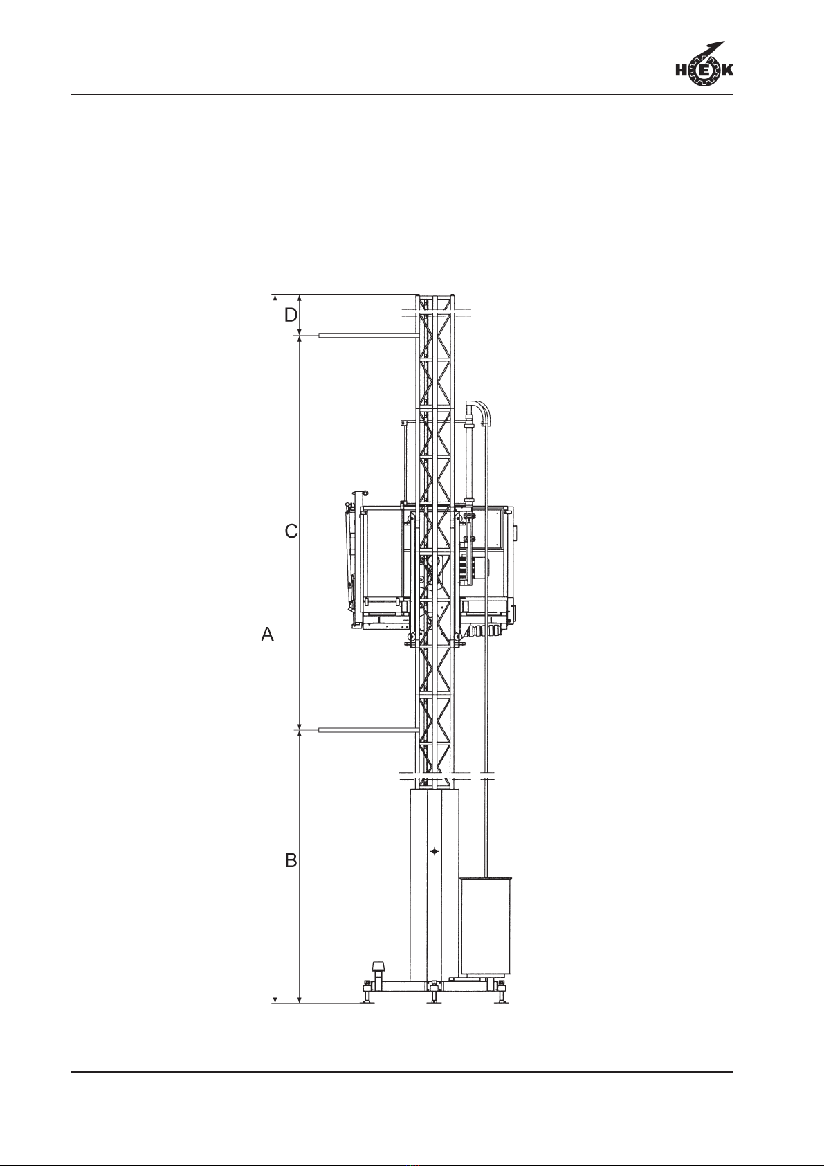
Fig.1-1 Dimensions

TECHNICAL DETAILS
1-1GTP 1500 •8095-007C
1. TECHNICAL DETAILS
Note:
The data in this chapter are based on standard applications for the GTP 1500
transport platform. In special situations, it may be possible to deviate from these
data. This may only be done, however, with prior written approval of the supplier.
1.1 General
See also fig. 1.1.
Description Fig.1-1 GTP 1500
Platform length [m / ft] 4.0 / 13.1
Platform width [m / ft] 1.5 / 4.9
Height of the platform fence [m / ft] 1.1 / 3.6
Distance between the anchors [m / ft] C 6 - 8 / 19.7 - 26.2
Max. mast height freestanding [m / ft] A 0 / 0
Max. mast height anchored [m / ft] A 120 / 393.6
Max. mast height above last anchor [m / ft] D 3 / 9.8
Mast type DRK400
Max. number of persons 7
Platform speed [m/min. / ft/min.] 12 / 39.4
Loading capacity [kg / lbs] 1,500 kg / 3,300 (see
chapter 1.4)
Distance between cable guides [m / ft] 6 / 19.7
Height of the first anchor for ground frame [m /
ft] B 3 - 4 / 9.8 - 13.1
Min. Platform height [m / ft] 0.40 / 1.31
Noise level < 70 dB
Weight of basic machine (incl. 2 mast
elements and 2 top masts [kg / lbs] 2,095 / 4,609
Transport wheels, type 195/70 R14
Tyre pressure transport wheels [bar] 2
Maximum wind-force during erection 12,5 m/s / 41.0 ft/s (6
Beaufort)
Maximum wind-force during use 15,7 m/s / 51.5 ft/s (7
Beaufort)
TECHNICAL DETAILS
1-2 GTP 1500 •8095-007C
1.2 Mast element
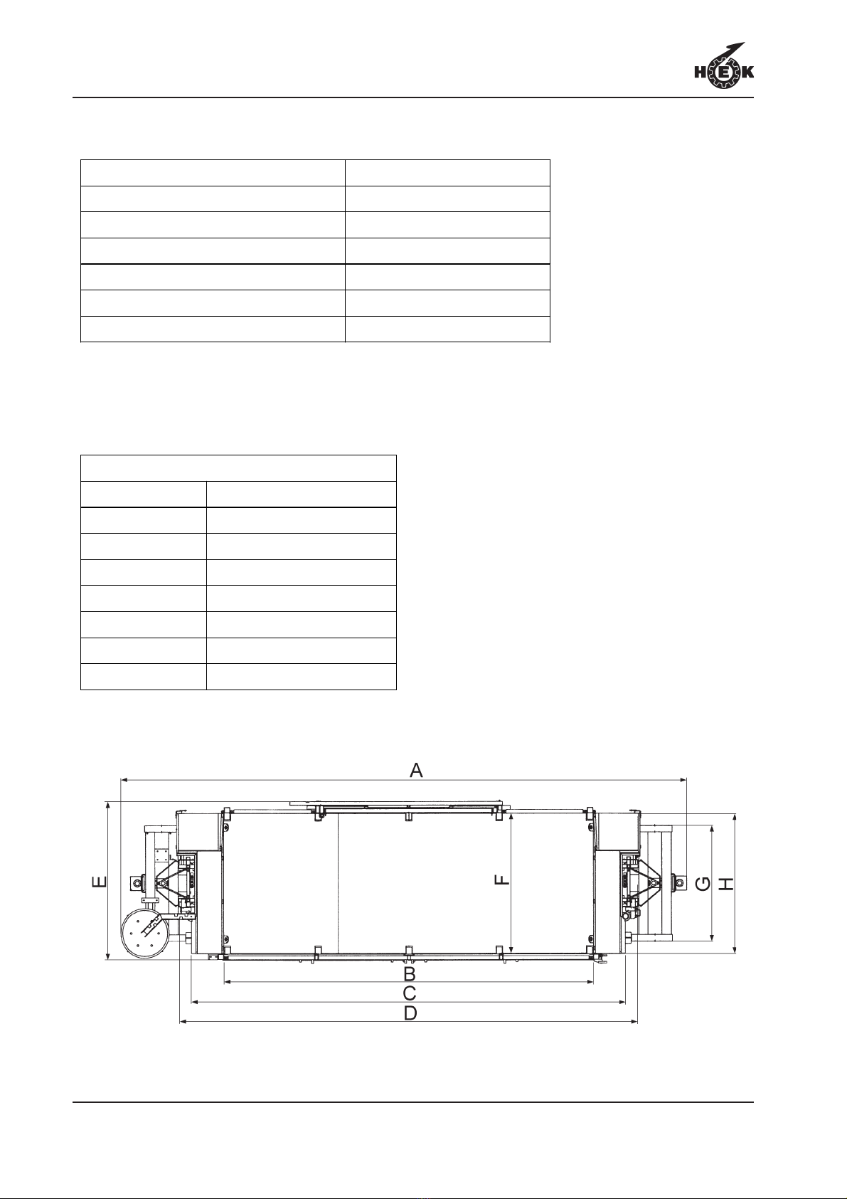
1.3 Dimensions GTP 1500
Fig.1-2 Dimensions top
Mast element length 1,508 mm / 59.4 In
Mast element width 400 mm / 15.6 In
Mast element depth 315 mm / 12.3 In
Modul rack 5
Mast bolts M14 x 90 Qual. 8.8
Tightening torque 100 Nm / 73.8 Lbft
Mast element weight 50 kg / 110 lbs
Fig.1-2, Dimensions [mm / In]
A 6,135 / 239.3
B 4,000 / 156.0
C 4,700 / 183.3
D 4,955 / 193.3
E 1,700 / 66.3
F 1,530 / 61.6
G 1,240 / 48.4
H 1,500 / 58.5

TECHNICAL DETAILS
1-3GTP 1500 •8095-007C
1.4 Electrical installation
GTP 1500 400V GTP 1500 230V
Number of motors 2 2
Rated power of work platform 2 x 4.8 kW 2 x 4.8 kW
Max. starting current 110 A 190 A
Power consumption based on S3-40% S3-40%
Power consumption 15 kVA 15 kVA
Power consumption at start up 70 kVA 70 kVA
Supply voltage 400 V 230 V
Minimum supply voltage 360 V 205 V
Phases 3 + N + Pe 3 + Pe
Supply frequency (depending on the
national conditions regarding to power
supply)
50 or 60 Hz 50 or 60 Hz
Fuse at building site (slow) 32 A 50 A
Control voltage 42 Vac 42 Vac
Control voltage frequency 50 / 60 Hz 50 / 60 Hz
up to 50 m 5 x 6 mm²4 x 16 mm²
Power supply cable
(to machine) up to 90 m 5 x 10 mm²4 x 25 mm²
up to 45 m 4 x 6 mm², 0.51
kg/m / 0.34 lbs/ft
up to 85 m
5 x 4 mm², 0.47
kg/m / 0.31 lbs/ft 4 x 10 mm², 0.91
kg/m / 0.60 lbs/ft
Machine cable /
Weight
up to 120 m 5 x 6 mm², 0.64
kg/m / 0.42 lbs/ft
4 x 16 mm², 1.27
kg/m / 0.84 lbs/ft
Single phase outlet 230 V ± 10% / 16 A 230V ± 10% / 16A
TECHNICAL DETAILS
1-4 GTP 1500 •8095-007C
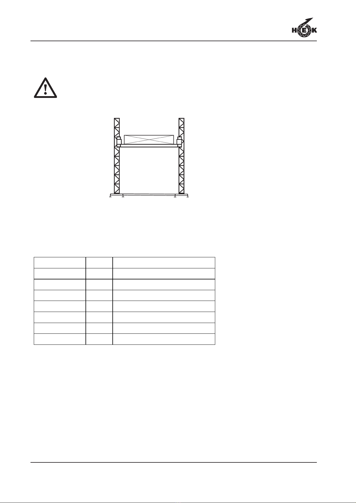
1.5 Transport platform loading
The payload must be equally distributed on the platform.
See the table for the maximum load and maximum number of persons.
Fig.1-3 Payload distribution
Persons + Load [kg / lbs]
1 (min.) + 1,400 / 3,080
2 + 1,300 / 2,860
3 + 1,200 / 2,640
4 + 1,100 / 2,420
5 + 1,000 / 2,200
6 + 900 / 1,980
7 + 800 / 1,760

TECHNICAL DETAILS
1-5GTP 1500 •8095-007C
1.6 Anchor forces
Tightening torque scaffold
coupling: 50 Nm / 36.9 Lbft
The anchor forces depends on the region
where the machine has to be placed. The
anchor forces in chapter 1.6.1 and 1.6.2
are given for the different wind speeds.
Contact your regional or national
meteorological institute to find out the
storm wind speeds applicable in the area
where the transport platform is being
erected.

TECHNICAL DETAILS
1-6 GTP 1500 •8095-007C
Fig.1-4 Anchoring to the scaffolding system
Conversion table
m ft
0.68 2.2
1.1 3.61
1.5 4.9
2 6.6
2.4 7.9
2.5 8.2
3.0 9.8
Scaffold section length 3,0 m / 9.84 ft
Storm Wind Speeds up to 46 m/s / 150 ft/s up to 53 m/s / 174 ft/s up to 59 m/s / 194
ft/s
F1 [kN /
lbf]
F2 [kN /
lbf]
F1 [kN /
lbf]
F2 [kN /
lbf]
F1 [kN /
lbf]
F2 [kN /
lbf]
* Mast height above last anchor =
3 m / 9.84 ft
* Loading ramp in the middle
5.8 /
1,305.0 3.6 / 810 5.8 /
1,305.0
4.7 /
1,057.5
* Mast height above last anchor =
0 m / 0 ft
* Loading ramp in the middle
4.9 /
1,102.5 3.6 / 810 4.9 /
1,102.5
4.7 /
1,057.5
* Mast height above last anchor =
3 m / 9.84 ft
* Loading ramp left or right
6.9 /
1,552.5 3.6 / 810 6.9 /
1,552.5
4.7 /
1,057.5
* Mast height above last anchor =
0 m / 0 ft
* Loading ramp left or right
5.7 /
1,282.5 3.6 / 810 5.7 /
1,282.5
4.7 /
1,057.5
Consult your dealer
1.6.1 Anchoring to a scaffolding
system
The anchor forces must be transferred to
the facade via the scaffolding system,
according to static requirements. The
transferred forces for the scaffolding
system must be static approved.

TECHNICAL DETAILS
1-7GTP 1500 •8095-007C
Scaffold section length 2.5 m / 8.2 ft
Storm Wind Speeds up to 46 m/s /
150 ft/s
up to 53 m/s /
174 ft/s
up to 59 m/s /
194 ft/s
F1 [kN
/ lbf]
F2 [kN
/ lbf]
F1 [kN
/ lbf]
F2 [kN
/ lbf]
F1 [kN
/ lbf]
F2 [kN
/ lbf]
* Mast height above last anchor = 3 m / 9.84 ft
* Loading ramp in the middle
7.2 /
1,620
3.6 /
810
8.0 /
1,800
4.7 /
1,058
* Mast height above last anchor = 0 m / 0 ft
* Loading ramp in the middle
6.1 /
1,373
3.6 /
810
8.0 /
1,800
4.7 /
1,058
* Mast height above last anchor = 3 m / 9.84 ft
* Loading ramp left or right
8.3 /
1,868
3.6 /
810
8.3 /
1,800
4.7 /
1,058
* Mast height above last anchor = 0 m / 0 ft
* Loading ramp left or right
6.9 /
1,553
3.6 /
810
8.0 /
1,800
4.7 /
1,058
Consult your
dealer

TECHNICAL DETAILS
1-8 GTP 1500 •8095-007C
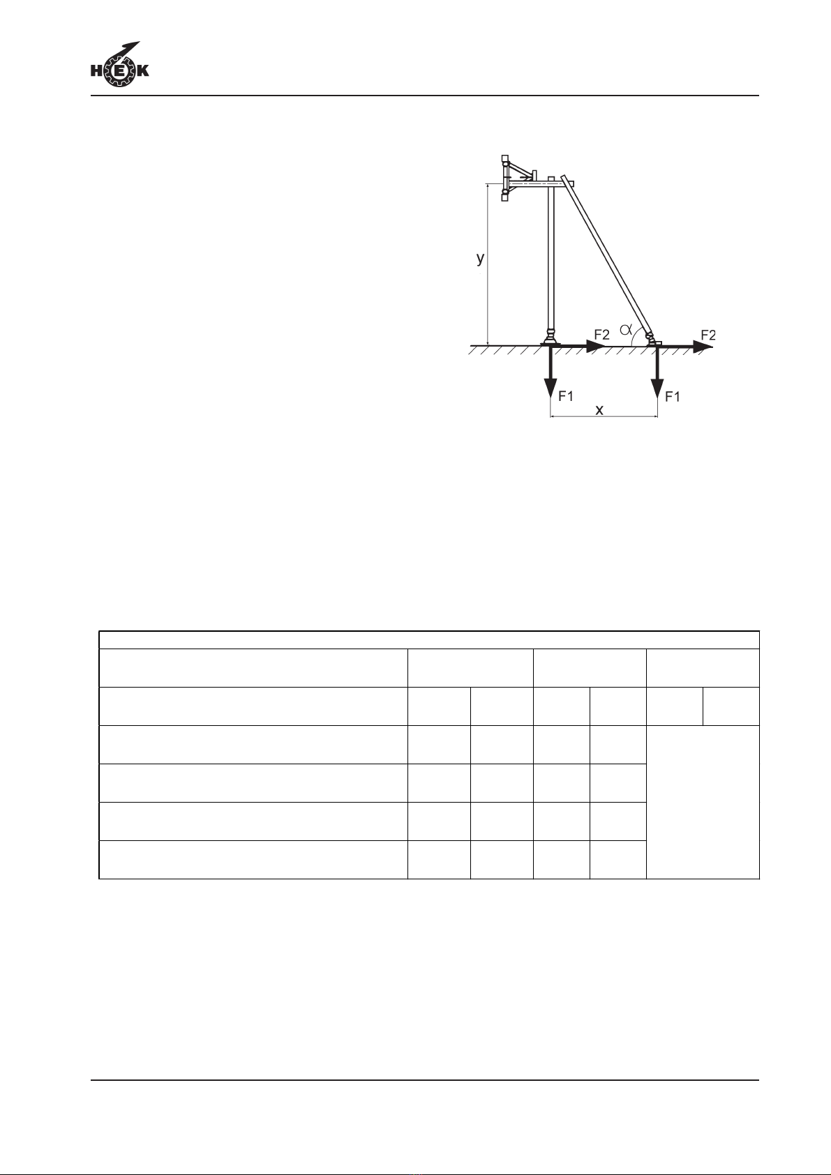
1.6.2 Anchoring to the facade
The anchor forces must be transferred to
the facade, according to static
requirements.
The anchor forces in table 1 are valid for
the following circumstances:
-α= 45°
- x = y = 1,5 up to 2,5 m / 4.9 up to 8.2 ft
For example:
- x = 1,8 m / 5.90 ft
- y = 1,8 m / 5.9 ft
- Loading ramp left
- Mastheight above last anchor = 3 m /
9.84 ft
- Region 46 m/s / 150 ft/s
See table 1: - F1 = 6.9 kN / 1,552.5 lbf
- F2 = 3.6 kN / 810 lbf
Fig.1-5 Anchoring to the facade
Table 1. Anchor forces to the façade (α= 45°)
Storm Wind Speeds up to 46 m/s / 150 ft/s up to 53 m/s / 174 ft/s up to 59 m/s / 194
ft/s
F1 [kN /
lbf]
F2 [kN /
lbf]
F1 [kN /
lbf]
F2 [kN /
lbf]
F1 [kN /
lbf]
F2 [kN /
lbf]
* Mast height above last anchor =
3 m / 9.84 ft
* Loading ramp in the middle
5.8 /
1,305.0 3.6 / 810 5.8 /
1,305.0
4.7 /
1,057.5
* Mast height above last anchor =
0 m / 0 ft
* Loading ramp in the middle
4.9 /
1,102.5 3.6 / 810 4.9 /
1,102.5
4.7 /
1,057.5
* Mast height above last anchor =
3 m / 9.84 ft
* Loading ramp left or right
6.9 /
1,552.5 3.6 / 810 6.9 /
1,552.5
4.7 /
1,057.5
* Mast height above last anchor =
0 m / 0 ft
* Loading ramp left or right
5.7 /
1,282.5 3.6 / 810 5.7 /
1,282.5
4.7 /
1,057.5
Consult your dealer
TECHNICAL DETAILS
1-9GTP 1500 •8095-007C
The anchor forces in table 2 are valid for
the following circumstances:
-α= 46°up to 60°
- y = 1,5 up to 2,5m / 4.9 up to 8.2 ft
- y / x = 1 up to 1,75
For example:
- x = 1,6 m / 5.25 ft
- y = 1,8 m / 5.9 ft
- Loading ramp left
- Mastheight above last anchor = 3 m /
9.84 ft
- y / x = 1,8/1,6 = 1,125
- Region C
See table 2: - F1 = 8,3 kN / 1,867.5 lbf
- F2 = 3,6 kN / 810 lbf
Fig.1-6 Anchoring to the facade
Table 2. Anchor forces to the façade (α= 46°to 60°)
Storm Wind Speeds up to 46 m/s /
150 ft/s
up to 53 m/s /
174 ft/s
up to 59 m/s /
194 ft/s
F1 [kN
/ lbf]
F2 [kN
/ lbf]
F1 [kN
/ lbf]
F2 [kN
/ lbf]
F1 [kN
/ lbf]
F2 [kN
/ lbf]
* Mast height above last anchor = 3 m / 9.84 ft
* Loading ramp in the middle
7.2 /
1,620
3.6 /
810
8.0 /
1,800
4.7 /
1,058
* Mast height above last anchor = 0 m / 0 ft
* Loading ramp in the middle
6.1 /
1,373
3.6 /
810
8.0 /
1,800
4.7 /
1,058
* Mast height above last anchor = 3 m / 9.84 ft
* Loading ramp left or right
8.3 /
1,868
3.6 /
810
8.3 /
1,800
4.7 /
1,058
* Mast height above last anchor = 0 m / 0 ft
* Loading ramp left or right
6.9 /
1,553
3.6 /
810
8.0 /
1,800
4.7 /
1,058
Consult your
dealer

TECHNICAL DETAILS
1-10 GTP 1500 •8095-007C
Table of contents
Other HEK Construction Equipment manuals


