Heliodyne Delta T Pro User manual

INSTALLATION
GUIDE
DELTA T PRO
CONTROL UNIT
EXCELLENCE
BY DESIGN

CONTROL OVERVIEW
This Delta-T Pro solar controller has been specifically designed
to control solar thermal collector systems, including open loop,
closed loop with a heat exchanger, drain back, residential
domestic water heating with electrical ignition gas single tank
storage, combination systems with space heating, and commercial
systems with variable speed pump operation.
There are two versions of the Delta-T Pro, one with a 10Base-T
Ethernet connection (DLTA 000 001), and one with a Wi-Fi/802.11b
Connection (DLTA 000 002).
The controller comes loaded with interface software, accessed
like a web page through any PDA, handheld, phone, laptop or
computer with a rich HTML internet browser such as Microsoft‘s
Internet Explorer. Connecting the control to an existing home or
office network will enable any user on that network to view the
system parameters and thermal performance data.
For the most basic system, the control requires two SAS-10
(10,000 Ohm @ 77°F) thermistor sensors, while additional
inputs are required to take advantage of the more sophisticated
operations, like energy calculation and data storage. Please
see the table at the end of this manual for functions and their
explanations, as well as the inputs required to run them.
1.0. Description
1. DELTA T PRO
ON:
OFF:
AUTO:
Relay Operation Bypass Pins
SHORT PINS 1-2 & 5-6
OPEN ALL PINS
SHORT PINS 1-2
Internally Powered Outputs
120 / 240 VAC
10kΩThermistor Sensors
100mA Fuse
Reset
WiFi:
Voltage Switch
6
5
4
3
2
1
3
2
1
3
2
1
Pin
JUMPER 5
JUMPER 6
Figure 1.0.-1 Delta T Pro I/O

CONTROL INSTALLATION 3
2.0. General Notes
This control conforms to the National Electric Code and is certified by the Underwriters Laboratory. Installation should adhere to all
national and local electric codes, and be installed by a qualified electrician or contractor. Any electrical wiring or modifications to the
control I/O should be performed with the power disconnected.
SOLAR HOT WATER
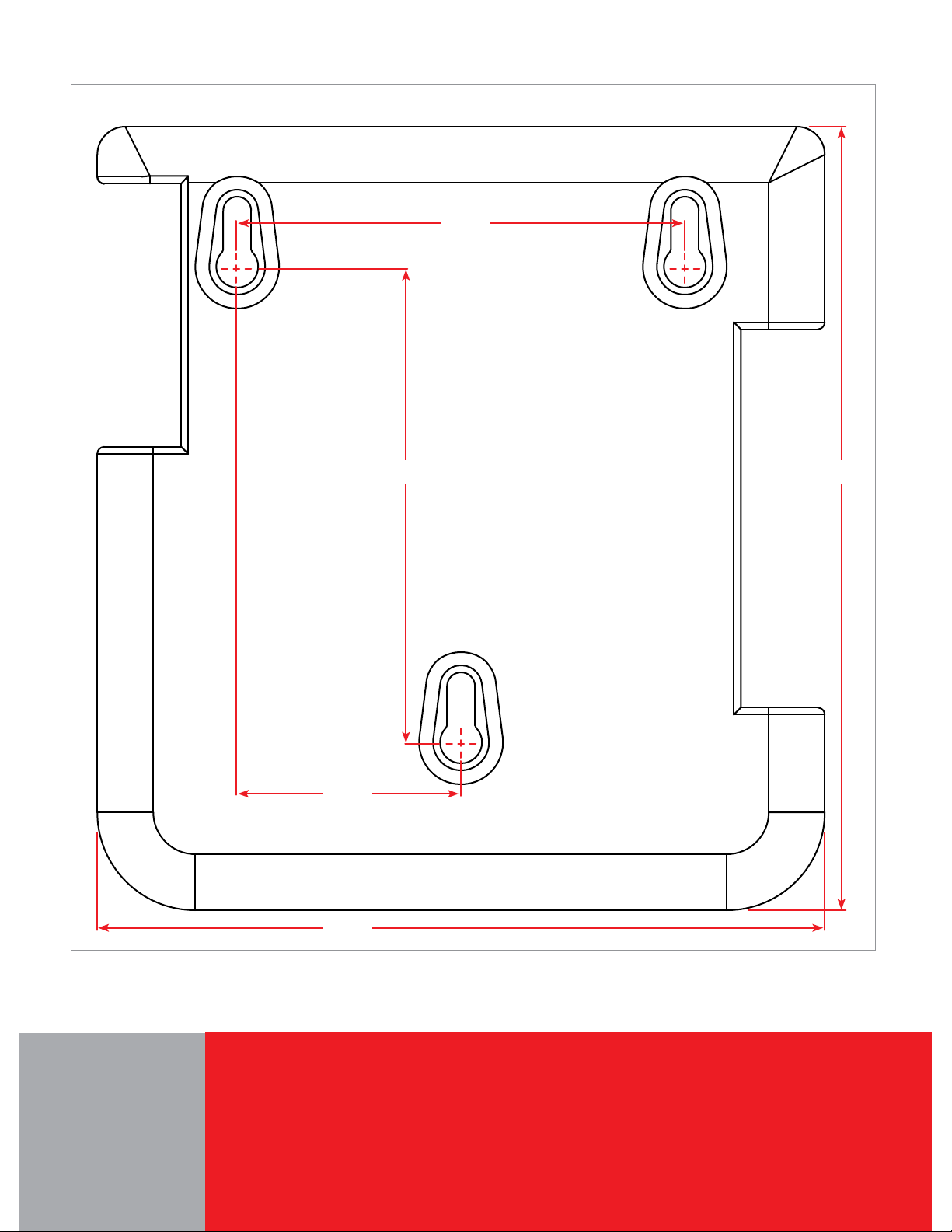
2.1. Mounting
The Delta-T Pro should be mounted on a wall indoors, away from
weather and interference. Using the mounting holes on the back
of the box, securely install 3 screws into mounting plane leaving
1/4” between the wall and the back of the bolt head; place control
back upon screws and slide down to secure box tightly into screw
pattern. The back page of this manual has a screw template.
2.2. Power and Wiring
This control comes pre-wired with an electric line cord for plug-in operation. The voltage is factory set to accept 115 VAC nominal.
If 230 VAC operation is desired, switch the red slider to reveal 230; modification of the line cord may be necessary to adapt to the
field plug receptacle. The operation voltage determines the relay output voltage.
Wire solar loop pumps into Relay 1, using the Normally Open (NO) terminal on the relay. The Normally Closed (NC) terminal can be
used to supply power to a unit for use when the collectors are not heating the storage, like a swimming pool or hot tub. See Figure
2 below, and the reference table at the end of this manual for use descriptions.
2.3. Thermistor Sensors
The SAS-10s sense temperature by conduction, and are not for liquid immersion, or inside collectors.
For a proper reading, ensure the copper lug on the sensor is firmly against the desired surface using
an SS pipe clamp across the flat surface or bolted via the through hole. Use surrounding insulation
to avoid ambient temperature and other sources of reading interference.
The sensor leads are 24 GA Class II wiring and carry 4 VDC. Use a conductor 18-24 GA zip or bell
wire to run from the sensor location to the control. Use caution when installing to avoid wire damage.
Shielded wire is not necessary.
2. INSTALLATION
Solar Loop
Connections
Connection for powering use
opposite to solar operation Temperature operated relay for Combi-Systems, etc*
*The minimum operation temperature is user set
Gas tank operation in DHW mode
OR
Extraneous heat use in Combi mode*
Figure 2. Relay Connections

CONTROL SETTINGS
3. SETTINGS
3.0. Network Connection
The Delta-T Pro comes preset with network parameters that in
most cases will not be compatible with existing network configu-
rations.
IP Address: 169.254.148.50
Subnet Mask: 255.255.0.0
Gateway: 169.254.148.1
If the above parameters are acceptable to your current configu-
ration, connect an Ethernet cable to the RJ 45 jack on the con-
trol, and connect the other end into your network hub. If these
settings must be adapted for your existing network, or you do
not have a network, then you must connect the Ethernet cable
directly to your computer to view the software.
After connection, wait for the computer to resolve the IP address
(up to 30 seconds depending on computer speed), then enter
the IP Address above into an internet browser to bring up the
system user interface.
3.1. Helio-Pak Pro Systems and DLTA 000 002
The Helio-Pak Pro systems and DLTA 000 002 come pre-pack-
aged with the Wi-Fi signal and the appropriate network settings.
Users must disable any ethernet connection first, and then can
connect to the “DTT Pro WiFi” network with a Wi-Fi enabled
device when the Helio-Pak is installed and powered up.
3.2. Changing the Network Settings on the 001
If the above parameters are not acceptable to your network con-
figuration, the control must be directly hooked up to a computer
or laptop with an RJ 45 / Ethernet port. (DLTA 000 002 WIFI
models are part of an Ad Hoc network, and the settings cannot
be changed at this time.)
With the control connected and powered up, enter the above IP
Address into an internet browser. After it has loaded, navigate
to the “Settings” page, then to the “Network” tab on the settings
page. Enter the appropriate site specific network parameters
into each box and write them in this manual using a pencil in
case of modifications:
My IP Address:
My Subnet Mask:
My Gateway:
Now press “Save”. You will no longer be able to access the
control via the default address, and must now use the last saved
IP Address to access the control software. If the last setting is
unknown, short the reset pins 1&2 at Jumper 5 directly on the
board, and press the reset button. The default network settings
and password have been reset. See Figure 1 for JP5 location.
3.3. Setting the System Clock
After the network settings have been adjusted to meet the
installed environment, the system clock must be set to ensure
optimal system performance and accurate energy graph data.
3.4. Setting System Parameters
The default operation setting for the Delta-T Pro is closed loop
residential domestic water heating system. If this configuration
does not match what has been installed, the operation system
type must be changed immediately before the control is set into
operation. For more information on functions and settings, see
the table at the end of this manual.
The Delta-T Pro has many user adjustable functions which can
be accessed via the settings page, behind a password protected
area. The user and changeable default password are:
User name: Admin
Password: caution
hp://169.254.148.50/
CONTROL SOFTWARE MAP 5
SOLAR HOT WATER
169.254.148.50:80.
INDEX
Navigation
Bar
50
0
1
148
0
148
254
255
254
80
169
255
169

SOFTWARE OVERVIEW / SETTINGS
4.1. Energy Page Graphs4.0. Energy Exporting
4.2. Settings Page
TAB VARIABLE VARIABLE TITLE DESCRIPTION
Sys System Controlled System System selection and description: 1 = Open Loop, 2 = Closed Loop Residential,
3 = Closed Loop Commercial, 4 = Combination DHW + Heating (Default = 2)
Password Settings Password Change password from the default “caution” password.
Press the reset button on the control PCB for changes to take effect.
Advanced Settings Opens the advanced system settings page
Download System
Energy
Opens a new window with text values in comma delimited format of stored system data
Right click on the link and choose save as for best formatting results.
Time Current Time Adjust current hour and minute of 24 hour system clock
Current Date Adjust current day of system clock
Network IP Address Browser address for accessing user software
Subnet Mask Value for network subnet control is installed on
Gateway Address of network gateway
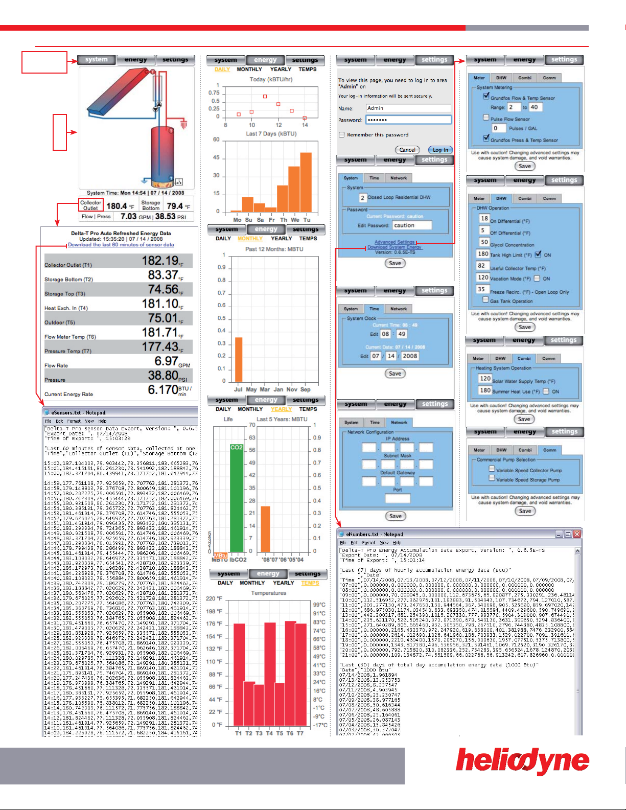
4. SOFTWARE
DAILY: Displays two graphs; the top graph displays
energy rate of collection for the current day, hour by
hour from the start of collection (in kBTU / hr). The
lower graph displays the collection over the week,
starting with the current day (in kBTU).
MONTHLY: Displays a graph with total monthly
collection for the past year, starting with the current
total for the current month (in MBTU).
YEARLY: Displays two graphs; the left side graph
contains information for the total system produc-
tion since control installation, showing CO2offset (in
1000 Lbs.) and energy production (in MBTU)
TEMPS: Displays the current temperature readings
for temperature sensors T1-T7.
T1 Collector Outlet T5 Outdoor Ambient
T2 Storage Bottom T6 Digital Sensor Temp @ Flow
T3 Storage Top T7 Digital Sensor Temp @ Pressure
T4 Hot into Heat Exchanger (Energy) or Indoor Ambient
Both versions of the Delta-T Pro store sensor and calculated energy data
in a comma delimited text file format for easy import into spreadsheet
applications. The Delta-T Pro can export:
eSensors.txt:1.
The past hour’s accumulated sensor readings (Temperature•
sensors 1 to 7, flow sensor and pressure sensor). Sensors not
connected will read 0.
eNumbers.txt:2.
Last (7) days of hourly energy production (BTU)•
Last (30) days of daily energy production (kBTU)•
Last (12) months of monthly energy production (MBTU)•
Last (5) years of yearly energy production (MBTU)•
Total energy production (MBTU)•
Total C0• 2offset (kLbs.)
Right click on the appropriate link and choose the “save as” option. If the
file to be exported has the same name as an existing file in that location,
you will need to change the name of the file you are saving for it to
export properly. Upon spreadsheet application import, choose “separate
columns by commas”.

FUNCTION REFERENCE 7
5.0. Advanced Settings Page Function Reference
TAB VARIABLE TITLE DESCRIPTION DEFAULT
Meter
Grundfos Flow & Temp
Sensor Checkbox for use of a digital Grundfos flow and temperature sensor checked
Range Text field for entering range of Grundfos flow sensor in Liters / Minute 2-40
Pulse Flow Sensor Checkbox for use of a pulse (analog) type flow meter unchecked
Pulses / GAL Text field for entering pulse meter calibration value 0
Grundfos Press & Temp
Sensor Checkbox for use of a digital Grundfos pressure and temperature sensor unchecked
DHW
On Differential Value in °F (T1) must be greater than (T2) by to turn solar loop circulators on 18 / CL, 9 / OL
Off Differential Value in °F (T1) must be equal to or less than (T2) to turn solar circulators off 5 / CL, 4 / OL
Glycol Concentration Percent by volume of glycol to water (Volume Glycol / Total Collector Volume * 100) 50 / CL, 0 / OL
Tank High Limit Highest storage tank value accumulated in °F read from (T3) or the average of (T2,
T3 if installed) if checked. Always use a cold water mixing valve to prevent scalding. 180, checked
Useful Collector Temp Lowest value in °F read at (T1) for solar loop operation with a satisfactory differential 80
Vacation Mode Value in °F read at (T3) for which collectors radiate storage tank heat through
collectors at nightime (with correct system clock setting), if checked.
120,
unchecked
Freeze recirc Value in °F read at (T1) at which collectors will circulate water to prevent freeze OL only
Gas Tank Operation Operates Relay 3 for use in conjunction with single tank gas storage systems. For
use only with electrical ignition gas tanks. May lower system overall performance. unchecked
Combi
Solar Water Supply Temp Minimum value in °F read at (T3) or average of (T2, T3 if installed) to operate
Relay 2, provided system selection = 4 and any Thermostat input is closed 120
Summer Heat Use Minimum value in °F read at (T3) or average of (T2, T3 if installed) to operate Relay
3, provided system selection = 4 and box is checked Unchecked
Comm
Variable Speed Collector
Pump
Operates 4-20 mA controlled current output (C1) for variable speed pump operation
on collector pump when checked. Adjusts pump speed to match optimum
differential throughout solar day, while minimizing parasitic pump electricity for
maximum payback. When used in conjunction with High Limit, slows down pump
as high limit is approached to avoid collector stagnation. Relay 1 is operated if
there is no variable speed storage side pump.
Unchecked
Variable Speed Collector
Pump
Operates 4-20 mA controlled current output (C2) for variable speed pump
operation on storage side pump when checked. Adjusts pump speed to match
optimum differential throughout solar day, while minimizing parasitic pump
electricity for maximum payback. When used in conjunction with High Limit (High
Limit is checked), slows down pump as high limit is approached to avoid collector
stagnation.
Unchecked
SOLAR HOT WATER
5. ADVANCED SETTINGS
5.1. Useful Conversion Factors
1 kBTU = 1,000 BTU; 1 MBTU = 1,000,000 BTU; 1 THERM = 100,000 BTU; 1 kWh = 3,412 BTU
Heliodyne, Inc. • 4910 Seaport Avenue • Richmond, CA 94804
T: 510.237.9614 • F: 510.237.7018
www.heliodyne.com
7.00”
SCALE = 1:1
4.25”
2.00”
6.50”
7.00”
Delta-T Pro Case Mounting Template
Other manuals for Delta T Pro
1
Table of contents
Other Heliodyne Control Unit manuals


Popular Control Unit manuals by other brands


Honeywell
Honeywell RV181 installation instructions

encompass
encompass AccuMax Quantum Usage instructions

IFM
IFM ecomatDisplay CR1202 operating instructions

Magnum Energy
Magnum Energy ME-CB installation manual

CG Products
CG Products Delay1022 instructions

Extron electronics
Extron electronics TLP 350MV Setup guide