Heliodyne DELTA T 84 User manual

INSTALLATION
GUIDE
DELTA T 84 & 94
CONTROL UNIT
EXCELLENCE
BY DESIGN
CONTROL OVERVIEW & INSTALLATION
1.0. Description
This Delta-T solar controller has been
specifically designed to control the basic solar
thermal collector system, including open loop,
closed loop with a heat exchanger, and drain
back, for residential domestic water heating
There are two versions of the Delta-T, the 84
is a hardwire model and can be supplied with
120 VAC or 240 VAC. The 94 model comes
with a pre-wired plug and grounded outlet for
installation ease.
For operation, the control requires two SAS-
10 (10,000 Ohm @ 77°F) thermistor sensors.
The differential and other settings have limited
adjustability using the DIP switch on the
control PCB.
1.1. General Notes
This control conforms to the National Electric Code and is certified
by ETL. Installation should adhere to all national and local electric
codes, and be installed by a qualified electrician or contractor. Any
electrical wiring or modifications to the control I/O should be per-
formed with the power disconnected.
1.2. Mounting
The Delta-T should be mounted on a wall indoors, away from weather
and interference. Using the mounting holes on the back of the box,
securely install 3 screws into mounting plane leaving 1/4” between
the wall and the back of the bolt head; place control back upon
screws and slide down to secure box tightly into screw pattern. The
back page of this manual has a screw template.
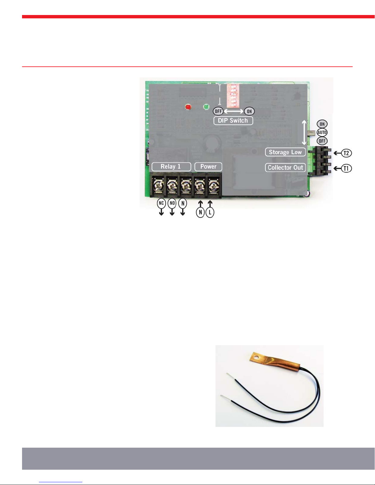
1.3. Power and Wiring
Wire solar loop pumps into Relay 1, using the Normally Open (NO)
terminal on the relay. The Normally Closed (NC) terminal can be
used to supply power to a unit for use when the collectors are not
heating the storage, like a swimming pool or hot tub. The voltage of
the controller will determine the relay output voltage.
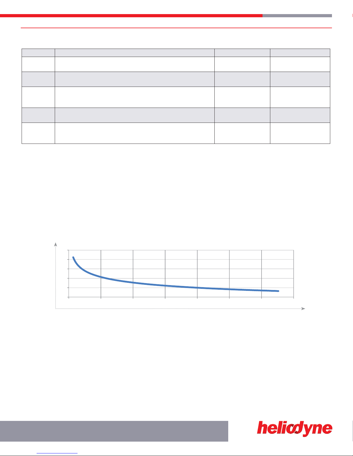
1.4. Thermistor Sensors
The SAS-10s sense temperature by conduction, and are not for liquid
immersion, or inside collectors. For a proper reading, ensure the
copper lug on the sensor is firmly against the desired surface using
an SS pipe clamp across the flat surface or bolted via the through
hole. Use surrounding insulation to avoid ambient temperature and
other sources of reading interference.
The sensor leads are 24 GA Class II wiring and carry 4 VDC. Use a
conductor 18-24 GA zip or bell wire to run from the sensor location
to the control. Use caution when installing to avoid wire damage.
Shielded wire is not necessary.
Install the collector sensor on the outlet header connection; install
the tank sensor on the bottom of the storage tank, so it is in contact
with the metal part of the tank. Insulate the sensors from ambient
conditions.
1.6. Operation
The function switch on the right side of the controller should be
set in the center, ‘AUTO’, position for automatic pump control.
When the switch is in the ‘ON’ position, Relay 1 will be on
continuously, regardless of temperature difference. With the
switch in the ‘OFF’ position, Relay 1 will remain off.
1. DELTA T
Internally
Powered Output
Power
Pumping
10kΩ
Thermistors
1
2
3
4
5
6
BIT
Figure 1.0.-1 Delta-T 84 / 94 I/O
Figure 1.4.-1 SAS-10 Sensor
CONTROL SETTINGS, TROUBLESHOOTING AND WARRANTY 3
1.5. DIP Switch Settings
BIT SWITCH # FUNCTION DESCRIPTION SETTING WHEN LEFT (OFF) SETTING WHEN RIGHT (ON)
1Tank high limit shutoff - automatically turns off Relay 1 when the
storage sensor reads switch 4 setting of 160 or 180°F No high limit function High limit ON
2Freeze recirculation - automatically turns on the
Relay 1 when the collector sensor reads 42°F or below No freeze recirculation Freeze recirc. ON
3
Useful collector temperature - automatically turns off Relay 1 when
the collector sensor reads 80°F or below, even with a satisfactory
differential (Freeze recirc. can override this function)
No useful collector
temperature monitor
Useful collector
temperature monitor ON
4Tank high limit shutoff temperature - choose which temperature to
turn the tank off at 160 or 180°F 180°F 160°F
5 &6
Differential setting - sets which temperature differential will turn on
and off Relay 1 (Heliodyne recommends both switches OFF for glycol
systems, and both switches ON for open loop or direct systems)
18°F ON
5°F OFF
9°F ON
4°F OFF
1.7. Troubleshooting
If a controller stops working, most often it is due to a sensor or wire failure. Detach
the sensor plug and measure the sensor resistance with a multi-meter and compare
with the chart below for appropriate reading values. Because they are inversely
related to temperature, a short reads as a very hot temperature, and an open reads
as a very cold temperature.
1.7.0. On/Off Test
This test verifies the controller will turn on and off. Switch the controller ‘ON,’ power
is applied to the Normally Open relay point, terminal 2. This may be verified with an
DC voltmeter across terminals 2 and 3. If a pump is connected, it should turn on.
With the switch in the ‘OFF’ position, power is applied to the normally closed relay
point, terminal 1. This may be verified with a voltmeter across terminals 1 and 3.
When the switch is ‘ON’, the pump LED indicator should be on. If not, consult the
manufacturer.
1.7.1. Basic Function Test
This test verifies the BIT settings are working correctly. The BIT switches (figure 2)
for a particular function must be on to test for that function.
Place BIT switches 1 on and 2 off (remaining switches can be either on or off.)
Switch controller to ‘AUTO.’ Allow the sensors to come to thermal equilibrium
(about one half hour.) Short the screws in positions (see figure 4) 1 and 2 and the
controller should turn on. Next, place the collector sensor in a cup of hot water;
this should turn the controller on. With the storage sensor screws shorted (positions
3 and 4), the controller should turn off. If the controller does not respond to these
tests, consult the manufacturer.
2.0. Warranty
HELIODYNE shall provide a one-year warranty for defects in compliance with the purchased goods
delivered after 3/1/2008 as follows: Objects are warranted at HELIODYNE’s discretion by repair of
the object of purchase or replacement of defective parts, exchange or reduction of price. The right of
the contractor to convert objects is ceded by common consent. Replaced parts become the property
of HELIODYNE. Wages and costs spent on installation and disassembly must be covered by the
client. This provision similarly applies to all warranty agreements. It is at HELIODYNE’s discretion
to replace defective goods with similar, faultless goods. In this case, any rights to cancel the
agreement cease. The client expressly waives the right for it and its legal successors to assert claims
for damages or loss of profit (including without limitation special, indirect, loss of use, contingent,
or consequential damages) due to defects or nonconformity in the purchased good. The warranty
set forth above constitutes the sole and exclusive remedy against HELIODYNE for the furnishing
of any nonconforming or defective goods. THE ABOVE WARRANTY IS EXPRESSLY IN LIEU OF
ALL OTHER WARRANTIES, EXPRESS OR IMPLIED, INCLUDING WITHOUT LIMITATION ANY
WARRANTY AS TO MERCHANTABILITY OR FITNESS FOR A PARTICULAR USE OR PURPOSE.
Damage resulting from improper or negligent treatment is excluded from the warranty. Claims on
warranty will only be admitted and considered if they are announced in writing immediately after the
defect was first noticed. Oral communication or communication by telephone are not sufficient.
For collectors (except broken glass and collector accessories e.g. sheet metal edgings) and storage
tanks (except attached components), HELIODYNE replaces materials that demonstrably fail to
meet one of the requirements of the ASHRAE standard 93-77 at no charge, works within five years
for storage tanks and ten years for collectors, of the date of the invoice issued by the company
HELIODYNE. HELIODYNE is not liable, however, for damage caused by mechanical stress and/
or changes caused by weather-related influences. Minor variations in color and/or damage to the
surface that have no effect on the function of the collector are also not covered in the warranty.
The warranty excludes damage caused by force majeure and malfunction that are due to improper
assembly, and/or product installation. HELIODYNE is not liable for possible costs resulting from
defects. In order for HELIODYNE to accept liability:
– Installation must have been carried out by a licensed specialized company (heating contractor or
plumber) following the version of installation instructions in force;
– HELIODYNE or its representative was given the opportunity to check complaints on site
immediately after any defect occurred;
– Confirmation exists that the system was commissioned properly and that the system was checked
and maintenance was performed annually by a specialized company licensed for this purpose. The
warranty agreed by HELIODYNE is only valid for their clients.
SOLAR HOT WATER
Ωvs °F
0
50
100
150
200
250
0 5,000 10,000 15,000 20,000 25,000 30,000 35,000
SENSOR TEMPERATURE °F
MEASURED RESISTANCE Ω

Heliodyne, Inc. • 4910 Seaport Avenue • Richmond, CA 94804
T: 510.237.9614 • F: 510.237.7018
www.heliodyne.com
4.61”
SCALE = 1:1
2.56”
1.57”
5.64”
3.15”
Delta-T Case Mounting Template
This manual suits for next models
1
Table of contents
Other Heliodyne Control Unit manuals


Popular Control Unit manuals by other brands

Cooper Security
Cooper Security Scantronic 9853 Update guide

Flowserve
Flowserve NAF-Setball Maintenance and installation instructions

Franke
Franke ZAQUA029 Installation and operating instructions

Ross Controls
Ross Controls CrossCheck CC4 Series Integration guide

Addi-Data
Addi-Data MSX-E1701 manual

Emerson
Emerson Keystone 990 Installation, operation and maintenance guide


