Helios FM441W User manual

HELl~S®
Full
Motion
In-Wall
TV
Mount
IMPORTANT SAFETY
INSTRUCTIONS:
When using a
mounting
system, basic precautions
should always be followed,
including the following:
Read
all instructions before
using (this
mounting
system).
DANGER
-
To
reduce
the
risk
of
electric shock:
1.
Use
this
mounting
system
only
for its intended use
as
described in these instruc-
tions. Do
not
use attach-
ments
not
recommended
by
the
manufacturer.
2.
Never
drop
or insert any
object into any opening.
3.
Do
not
use
outdoors.
SAVE
THESE
INSTRUCTIONS
Installation Instructions for:
televisions
with
a
maximum
60"
diagonal screen,
weighing
up
to
75 pounds.
FM441W
Carefully read all instructions
before beginning installation.
At least 2 people are required
to
install
the
In-Wall
TV
Mount,
especially when
mounting
TV.
To
avoid
possible injury
or
damage,
DO NOT
attempt
to
mount
the
TV
alone.
Tools
You
Will Need:
12mm
Drill Bit and Drill
CuttingTool
for
Wall Opening
Basic
HandTools
Tape Measure
NOTE: Installation must be made
into
awall constructed using 2x4 studs positioned on 16"centers.The location should be
safe from hazards such
as
water
or
crushable items.
DO NOT ATTEMPT TO INSTALL
OR
USE
THIS
MOUNT
IN ANY
WAY
OTHER THAN DESCRIBED IN
THESE
INSTRUCTIONS.
Use
onlythe supplied hardware listed bel.ow intended for the current application
to
avoid personal injury or propertydamage.
Installation
Hardware
(included)
P"""""""
8mm
Lag
Bolt
x4
8mm Plastic Anchor
x4
0 c-- @
8mm Nut 8mm Allen Screw 8mm Washer
x8 x8 x8
Allen Wrench
x1
O!!!+
x4
~
x4
~
x4
TV
Mount
VESA
Hardware
(included)
{Olt,M4,
(fr-
I
x4
~-"'''
~
x4
x4
Ud,.41\mrn
x4
~.t
•.
J!J)1/'IHft
x4
x4
~
([aoJB111
l'All<ISfflm
~-111110
··--
x4
0@
,,._.
,
MS
W!tMI
x4
x4
x4
I(s~cer)I
t.imm
x4
Do
not
discard these instructions.
B
~
x4
x4
(spacer)
38mm
x4
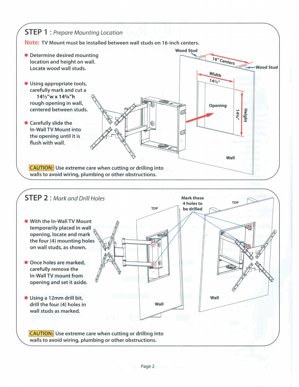
STEP
1 :Prepare
Mounting
Location
Note: TV
Mount
must
be installed between wall studs on 16-inch centers.
• Determinedesired
mounting
location and
height
on wall.
Locate
wood
wall studs.
• Using appropriatetools,
carefully markand
cut
a
14½"w
x
145/a"h
rough
opening
in wall,
centered between studs.
• Carefully slide
the
In-Wall TV
Mount
into
the
opening
until
it
is
flush
with
wall.
!CAUTION:!
Use
extremecare when
cutting
or
drilling
into
walls
to
avoid
wiring,
plumbing
or
other
obstructions.
STEP
2 :Mark
and
DrillHoles
• With
the
In-Wall TV
Mount
temporarily
placed
in
wall
opening, locate and
mark
'
the
four
(4)
mounting
holes '
on wall studs,
as
shown.
• Once holes are marked,
carefully remove
the
In-Wall TV
mount
from
opening
and set
it
aside.
• Using a 12mm
drill
bit,
drill
the
four
(4)
holes
in
wall studs
as
marked.
TOP
Wall
!CAUTION:!
Use
extreme care
when
cutting
or
drilling
into
walls
to
avoid wiring,
plumbing
or
other
obstructions.
Page 2
1~
th
,-.__
14
~ 1
--
Opening
Mark
these
Wood Stud
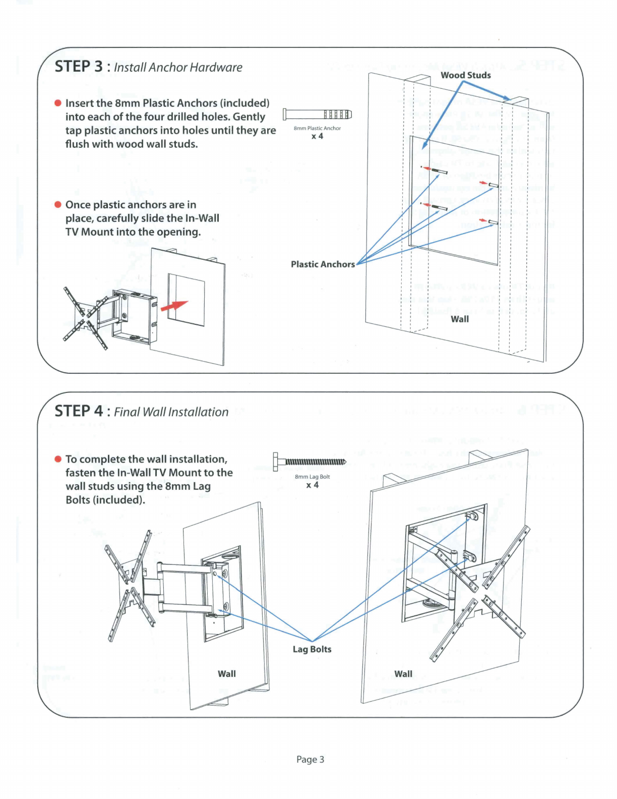
STEP
3 :InstallAnchorHardware
• Insert
the
8mm
Plastic Anchors (included)
into
each
of
the
four
drilled
holes. Gently
□
>---~ff
D~D-D-~J
tap plastic anchors
into
holes
until
they
are
flush
with
wood
wall studs.
• Once plastic anchors are in
place, carefully slide
the
In-Wall
TV
Mount
into
the
opening.
STEP
4 :Final Wall Installation
8mm
PlasticAnchor
x4
Plastic Anchors
•
To
complete
the
wall installation,
fasten
the
In-WallTV
Mount
to
the
wall studs using
the
8mm
Lag
Bolts (included).
~IHUl\ll\U\m\lll\l\ll>
8mm
Lag
Bo
lt
x4
Wall
Page3
Wall

STEP
5 :
Attach
VESA
Mounting
Plate
to
TV
VESA
mount
pattern
VESA
Hardware
(varies byTV)
• Determine
the
VESA
mount
pattern
for
your
TV.
The
VESA
Plate shown
will
accomodate
VESA
patterns
from 75x75
to
250x250.
If
your
TV
falls
within
this range, align and
attach
VESA
Plate
to
TV using
optimum
combination ofVESA
hardwareand spacers (included).
SinceTV modelsvary, consult
your
TV documentation
or
manufacturer
for more
information.
(you,TVmay
~••
If
your
TV
uses
a
VESA
pattern
larger than
250x250,
skip this step
and proceed to Step 6 (below)
STEP
6 :
Attach
VESA
Mounting
Plate
with
Extension Arms
to
TV
• For larger
VESA
mount
patterns
from
250x250
up
to
400x400, attach
the
four
(4)
Extensions Arms
to
the
VESA
Plate using
the
eight
8mm
Allen Screws,
Washers and Nuts (included),
as
shown below.
TV
........_
BmmNut
• Attach
VESA
Plate
with
Extension Arms
to
TV using
optimum
combination ofVESA
hardware and spacers (included). Since TV
models vary, consult
your
TV
documentation
or
manufacturer
for
more
information.
Page4
Extension Arms
VESA Hardware
(varies by
TV)
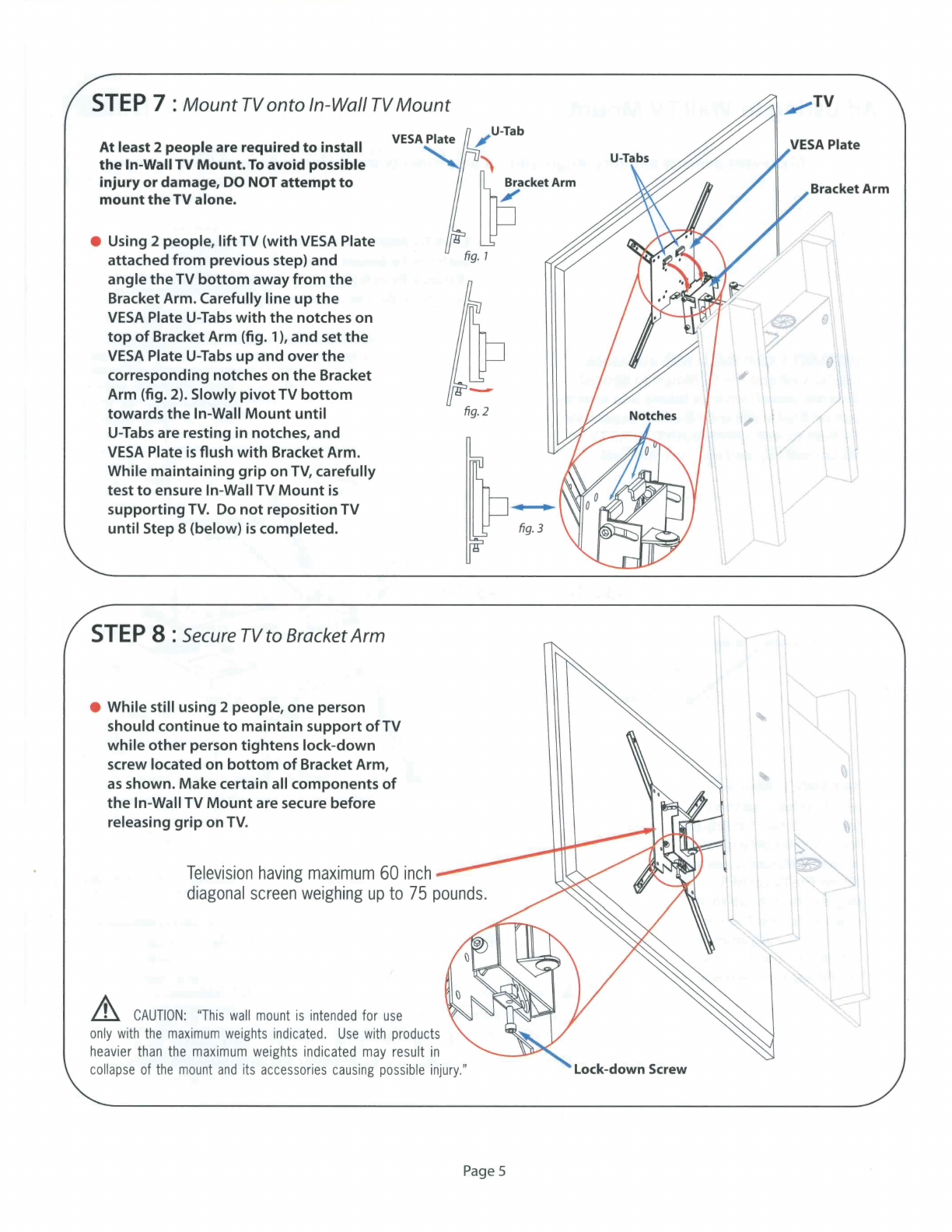
STEP
7 :
Mount
TV
onto
In-Wall TV
Mount
At least 2 peopleare required
to
install
the
In-WallTV Mount.
To
avoid possible
injury
or
damage,
DO
NOT
attempt
to
mount
the
TV alone.
e Using 2 people,
lift
TV
(with
VESA
Plate
attached
from
previous step) and
angle
the
TV
bottom
away
from
the
Bracket Arm. Carefully line
up
the
VESA
Plate U-
Tabs
with
the
notches on
top
of
Bracket Arm (fig. 1
),
and set
the
VESA
Plate
U-Tabs
up
and over
the
corresponding notches on
the
Bracket
Arm (fig. 2). Slowly
pivot
TV
bottom
towards
the
In-Wall
Mount
until
U-Tabs are resting
in
notches, and
VESA
Plate isflush
with
Bracket Arm.
While
maintain
ing
grip
on
TV,
carefully
test
to
ensure In-Wall TV
Mount
is
supporting
TV. Do
not
repositionTV
until
Step 8 (below)
is
completed.
STEP
8 :Secure TV
to
Bracket
Arm
• While still using 2 people, one person
should continue
to
maintain
support
of
TV
while
other
person
tightens
lock-
down
screw located on
bottom
of
Bracket Arm,
as
shown. Makecertain all components
of
the
In-Wall TV
Mount
are secure before
releasing
grip
on
TV.
,-
u-
Tab
:'\
~
,~A<m
fig.
7
-
fig.2
T
ele
v
isio
nha
ving
m
ax
imum60 i
nch
diag
on
al
scre
en
weigh
ing up
to
75
po
und
s.
.&,_
CAUTION:
"This
wal
l
mount
is
i
nt
en
d
ed
for
use
only
with
the
maximum
weights
indicated
.
Use
wit
h
products
heavier
t
han
the
maxim
um
we
igh
ts
indica
t
ed
may
resu
lt
in
collapse
of
the
mount
and
its
accessories
causing
possible
injury.
"
Page
5
"
I
I
Bracket Arm
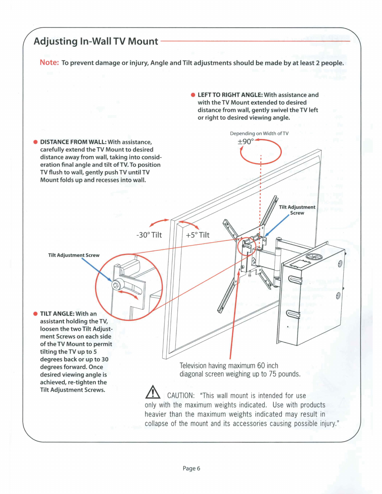
Adjusting
In-WallTV
Mount
Note:
To
prevent
damage
or
injury,Angle and
Tilt
adjustments should be made
by
at
least 2 people.
e DISTANCE FROM WALL: With assistance,
carefullyextend
the
TV
Mount
to
desired
distance away
from
wall,
taking
into
consid-
eration final angle and
tilt
ofTV.
To
position
TV flush
to
wall,
gently
pushTV
until
TV
Mount
folds
up
and recesses
into
wall.
e
TILT
ANGLE: With an
assistant
holding
the
TV,
loosen
the
two
Tilt Adjust-
ment
Screws on each side
of
the
TV
Mount
to
permit
tilting
the
TV
up
to
5
degrees back
or
up
to
30
degrees forward. Once
desired viewing angle
is
achieved, re-tighten
the
Tilt AdjustmentScrews.
-30°Tilt
e LEFT
TO
RIGHT ANGLE: With assistance and
with
the
TV
Mount
extended
to
desired
distance
from
wall,
gently
swivel
the
TV
left
or
right
to
desired viewing angle.
Depending onWidth
of
TV
0I
Television
having
maximum
60
inch
diagonal
screen
weigh
ing
up
to
75
pounds.
CAUTION:
"This
wall
mount
is
intended
for
use
only
with
the
maximum
weights
indicated.
Use
with
products
heavier
than
the
maximum
weights
indicated
may
result
in
collapse
of
the
mount
and
its
accessories
causing
possible
injury."
Page6

LIMITED
WARRANTY
HELIOS"'
Metra
Home
Theater-Limited Warranty -Valid in
the
United States and Canada
This 60
month
limited
warranty
is
provided
by
Metra Electronics Corporation
for
the
Metra
product
identified by
the
purchaser's registration
as
indicated below, and there are
no
other
warranties, expressed
or
implied, except
as
required
by
law,
including
warranties
of
merchantabilityand
fitness
for
a specific purpose,
that
are provided
for
herein, howeverall such
implied
warranties,
if
any, are
limited
to
the
duration
of
this specific
limited
product
warranty.Some states
do
not
allow
limitations
on
how
long an
implied
warranty lasts,
so
the
above limitations may
not
apply
to
you. Metra Electronics Corporation shall
not
be liable,
under
any circumstances,
for
incidental, indirect, special, and consequential
or
multiple
damages
as
a result
of
the
sale
or
use
of
this
product.
Some states/countries
do
not
allow
the
exclusion
or
limitation
of
incidental
or
consequen-
tial damages,
so
the
above
limitation
or
exclusion may
not
apply
to
you.
It
is
recommended
that
the
purchaserexecute
the
product
registration
and warranty registration via
the
web
within
ten days
of
purchase.
Limited ProductWarranty:
This
is
a 60
month
limited
warranty, subject
to
the
conditions, limitations and exclusions identified herein.Metra Electronics Corporation
warrants
to
the
original purchaser
of
the
registered
or
identified
product
for
a period
of
five years
from
the
date
of
purchase,
that
the
product
shall be free
of
defects in design, material and workmanship, and subject
to
the
limitations set
forth
below; Metra Electronics Corporation will
repair
or
replace, at its
option,
any defective unit.This warranty
is
applicable
only
to
the
original purchaser and
is
not
assignable
or
transferable.
Metra hereby warrants
to
the
original retail purchaser
of
this
product
that
should this
product
or
any
part
thereof,
under
normal use and
conditions, prove
to
be defective in material
or
workmanship
within
five years
from
date
of
original purchase, such defect(s) will be repaired
or
replaced
with
reconditioned
product
(Metra's
option)
without
charge
for
parts and repair labor. Purchaser
must
return
the
product
to
Metra,
return receipt requested
or
by
other
means
that
confirms delivery and Metra shall make
the
said repairs
or
replacement
within
60 days
of
receipt.
In some instances
the
product
may have been discontinued and
cannot
be replaced,
or
repaired.In
that
instance Metra shall in its discretion
attempt
to
replace
the
product
with
a substantially similar
product
in
model
or
design
or
pay
the
purchaser a sum
for
the
then
fair marketvalue
of
the
price, considering
the
amount
of
time
since
sale,
and
the
use
of
the
product.This Limited Warranty
is
the
original retail purchaser's sole
remedy
for
anyand all such defect(s).
Conditions and Limitations:
(1)
Proof
of
purchase
is
required (i.e.
the
sales receipt
or
other
proof
of
payment, such
as
the
bar code and serial
number
from
the
shipping
box), and
(2)
Products
must
be registered
with
Metra Electronics
by
using Metra's
online
services
at
www.metra-online.com
for
registration purposes.
Products
that
have
not
been registered will
not
be covered by Metra's extended
limited
five year warranty,
but
instead
will
only
be warranted
for
the
terms required by
the
State
of
purchase,
if
any.
(3)
Damage caused
by
accidents, abuse, misuse
or
modification
of
the
product
will render this warranty null and void.
(4)
To
obtain
repairs
or
replacement
under
the
terms
of
this warranty, please contact Metra at 1-800-221-0932
or
visit www.metra-
online.com.
You
will need
to
provide
proof
of
purchase (dated receipt showing store where purchased) and
product
serial
number
in order
to
receive warranty service.The purchaser
is
required
to
send
the
product
back
to
Metra Electronics Corp
or
to
a designated repair centerand
the
purchaser
is
responsible
for
all charges
for
shipping and handling.
This Limited Warranty does NOT cover:
Products
which
have been subject
to
abuse, accident, alteration, modification, tampering, negligence, misuse,
improper
installation, lack
of
reasonable care, unauthorized repair
or
service,
or
if
the
model
or
serial
number
has been altered, tampered
with,
defaced
or
removed.
Initial installation
or
the
removal and re-installation
of
product.
(1)
Cosmetic damage, damage
that
occurs in shipment, act
of
God
or
natural disaster.
(2)
Missing accessories
or
components.
(3)
Products used
for
any and all commercial purposes.
THE
EXTENT
OF
METRA'S
LIABILITY
UNDER
THIS
WARRANTY
IS
LIMITED
TO
THE
REPAIR
OR
REPLACEMENT
AS
PROVIDED
ABOVE
AND,
IN
NO
EVENT
SHALL
METRA
LIABILITY
EXCEED
THE
PURCHASE
PRICE
PAID
BY
THE
ORIGINAL
RETAIL
PURCHASER
FOR
THE
PRODUCT.
Any questions
of
Notifications regarding this warranty should be addressed to:
Warranty Department, Metra Electronics Corporation
460Walker Street, Holly Hill, Florida 32117.
THIS
WARRANTY
IS
IN
LIEU
OF
ALL
OTHER
EXPRESS
WARRANTIES
OR
LIABILITIES.
ANY IMPLIED
WARRANTIES,
INCLUDING ANY IMPLIED
WARRANTY
OF
MERCHANTABILITY,
SHALL
BE
LIMITED
TO
THE
DURATION
OF
THIS
WRITTEN
WARRANTY
.
IN
NO
EVENT
SHALL
METRA
BE
LIABLE
FOR
ANY
CONSEQUENTIAL
OR
INCIDENTAL
DAMAGES
FOR
BREACH
OF
THIS
OR
ANY
OTHER
WARRANTY
EXPRESS
OR
IMPLIED
WHATSOEVER.
No person
or
representative
is
authorized
to
assume
for
Metra any liability
other
than
expressed herein in connection
with
the
sale
of
this
product. Somejurisdictions
do
not
allow
limitations on
how
long an
implied
warranty lasts
or
the
exclusion
or
limitation
of
incidental
or
consequential damages
so
the
above limitations
or
exclusions may
not
apply
to
you.This warranty gives you specific legal rights and you may
also have
other
rights,
which
vary
from
jurisdiction
to
jurisdiction.
Page
7

,
HELl~S®
©2017 Metra Electronics
Corporation•
460 Walker Street• Holly Hill, FL• 32117-2699
Specifications
are
subject
to
change
without
notice. All trademarks are
the
property
of
their respective owners.
metrahometheater.com
FM44IW
866.839.9187 • www.metrahometheater.com
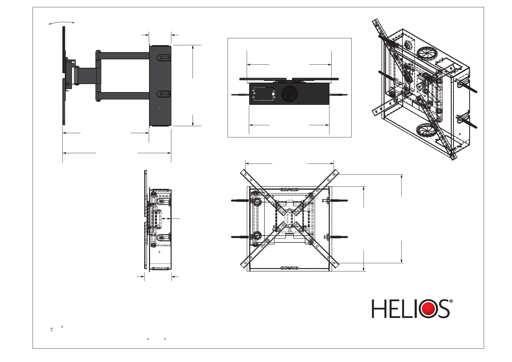
NOTES:
1. MAXIMUM WEIGHT CAPACITY = 75bs. (34kg)
2. VESA MOUNTING CONFIGURATION: 75MMx75MM up to 400X400MM
3. 90 INTERFACE LEFT/RIGHT SWIVEL
4. VIEWING ANGLE INCREMENTS: +5 ~-30
MAX. HORIZONTAL
VESA PATTERN
15.75”
[400 mm]
MAX.
VERTICAL
VESA PATTERN
15.75”
[400 mm]
15.10”
[383.555 mm]
OUTER
FLANGE
HEIGHT
4.81”
[122.184 mm]
MIN.
OVERALL
WIDTH
1.70”
[43.197 mm]
FOLDED
DISTANCE
15.10”
[383.555 mm]
OUTER FLANGE WIDTH
14.25”
[361.950 mm]
IN-WALL WIDTH
TOP VIEW
+30° -5°
15.47”
[392.931 mm]
MAX. DISTANCE
FROM WALL
19.42”
[493.253 mm]
MAX. OVERALL WIDTH
3.95”
[100.322 mm]
IN-WALL
DEPTH
14.50”
[368.300 mm]
IN-WALL
HEIGHT
Table of contents
Other Helios TV Mount manuals


