Helios FML64PL User manual

FML64PL
Assembly Instructions
• Please read these instructions carefully before using.
• This model will hold most 32-65 Flat Panel TVs.
• Load capacity: 34kg (75 lbs).
FML64PL
• Please read these instructions carefully before using.
• This model will hold most 32-65 Flat Panel TVs.
• Load capacity: 34kg (75Lbs).

FML64PL Information
• Please read these instructions carefully before starting.
• This product will hold most 32-65 Flat Panel TVs.
• Load capacity: 34kg (75 lbs).
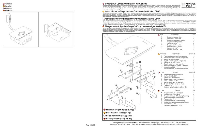
Supplied Parts and Hardware: (Some parts not shown at same scale)
1
option 1 VESA size:75*75mm,100*100mm.
2
figure 2
option 2 VESA size:(200-400)*600mm.
Instruction:Attach connecting plate (D) to arm (C) using 4 ,slide
TV bracket (B) onto (C).(figure 2).
Step 1:Read and understand all the directions,handle and use according to the directions
strictly.
Safety Directions:
Step 3:As per different VESA size to choose the suitable unit to assemble them.
Assembly Hareware:
Hardware for TV assembly:
2 - square head
screw 4pcs
3 - concrete
bolt 4pcs
1 - washer
4pcs
a- bolt
4pcs
b- bolt
4pcs
c- bolt
4pcs
d- bolt
4pcs
e- bolt
4pcs
g- washer
4pcs
h- washer
4pcs
i-spacer
4pcs
f- bolt
4pcs
j- wrench
1pcs
k- wrench
1pcs
4 - bolt
8pcs
44
Step 2:Remove the screws 5 to separate it into two parts.
FML64PL Safety
1
A--Wall plate 1pc
Supplied Parts and Hardware: Some parts not shown at same scale
Safety Warning: Thanks for choosing this Helios wall mount and please read these instructions
carefully before using the model FML64PL to avoid any injury of anybody and(or) any property
loss. If you do not understand these directions, or have any doubts about the safety of the
installation, please call a qualified contractor or contact Helios customer service department.
Please check carefully to make sure that there are no missing or defective parts. Our customer
representatives can quickly assist you with installation questions and missing or defective
parts. Replacement parts for products purchased through authorized dealers will be shipped to you
directly. Never use defective parts, improper installation may cause damage or serious injuiry. Do not
use this product for any purpose that is not explicitly specified by Helios. Helios is not liable for
damage or injury caused by incorrect mounting, incorrect assembly, or incorrect use.
C--Fixed arm
2pcs
B--TV bracket
2pcs
(Also Figure 8)
Rotate 90°
E- Slide Arm Plate
Figure 1
Figure 2
D- Connecting Plate

Safety Warning
Thank you for selecting the Helios FML64PL for your installation.
Before starting your installation please read and understand all of the
directions.
If you are unsure or have any doubts about the installation please contact
an installation professional or Helios customer support.
• Check the packing list and boxed products carefully to verify
that there are no missing and/or damaged parts.
• Never use damaged or incorrect parts to do your installation as
that may cause property damage or personal injury.
• Our customer service can quickly assist you with installation
questions or parts request.
• Do not use the Helios FML 64PL for any purpose other than
that specified by Helios. Helios is not liable for damage or injury
caused by incorrect assembly, mounting or use.
Helios customer support:
Hours: Monday – Friday, 9 AM to 7 PM
Phone Number: (866) 839-9187
Email: [email protected]om
Installation and Mounting Directions
Step 1: Read manual completely and understand all of the
directions prior to starting the installation.
Use FML64PL only as described in the directions.
Step 2:
Disconnect the Connecting Plate (D) from the articulated arm by
removing the screws at the bottom rear of the Connecting Plate (D) next
lift the Connecting Plate (D) up and away from the articulated arm.
Then remove the Slide Plate (E) from the Wall Plate (A) by loosing the
two bottom screws and lifting the Slide Plate (E) up and away from the
Wall Plate (A).
2
option 1 VESA size:75*75mm,100*100mm.
2
figure 2
option 2 VESA size:(200-400)*600mm.
Instruction:Attach connecting plate (D) to arm (C) using 4 ,slide
TV bracket (B) onto (C).(figure 2).
Step 1:Read and understand all the directions,handle and use according to the directions
strictly.
Safety Directions:
Step 3:As per different VESA size to choose the suitable unit to assemble them.
Assembly Hareware:
Hardware for TV assembly:
2 - square head
screw 4pcs
3 - concrete
bolt 4pcs
1 - washer
4pcs
a- bolt
4pcs
b- bolt
4pcs
c- bolt
4pcs
d- bolt
4pcs
e- bolt
4pcs
g- washer
4pcs
h- washer
4pcs
i- spacer
4pcs
f- bolt
4pcs
j- wrench
1pcs
k- wrench
1pcs
4 - bolt
8pcs
44
Step 2:Remove the screws 5 to separate it into two parts.
D
E
Figure 3

3
Installation and Mounting Directions
Step 3: Mount the Wall Plate (A) to the wall.
Drywall with Stud mounting: The Wall Plate (A) must be mounted directly
to two wood studs with a minimum distance of 16” between the studs. Once
you have located the correct studs and height for the installation, hold the
Wall Plate (A) in position against the wall, verify with a level and mark the bolt
location for each stud (Figure 1). Next drill 1/8” diameter, 1.25” deep hole at the
four marked locations. Attach the Wall Plate (A) onto the wall with the supplied
lags bolts, level and tighten the lags until Wall Plate (A) is secured.
Concrete Block & Brick mounting: The Wall Plate (A) must be mounted directly
to Solid Concrete, Concrete Block or Brick. Do NOT mount to Mortar joints
or hollow wall sections. Once you have located the correct location for the
installation, hold the Wall Plate (A) in position against the wall, verify with a level
and mark the bolt location for each lag. Next drill 3/16” diameter, 1.25” deep
hole at the four marked locations. Using 3/16” x 1.25” Hex Head Concrete screws
attach the Wall Plate (A) onto the wall with the supplied lags bolts, level and
tighten the lags until Wall Plate (A) is secured.
Note: Be sure to choose a high quality wall area and enough strong to hold the
weight of the TV and wall mount itself. The assembly place should be far
away from water and sunshine
Installation and Mounting Directions:
Step 1:Read manual completely and understand all of the directions prior to starting the installation.
Use (model number) only as described in the directions. .
Figure 1(keep the wall plate level)
Figure 2
Figure 3
Figure 4
Step 3:
Attach two brackets (B) to TV back.
Figure 5
Figure 6
2
Attention
Forbidden
Note: Be sure to choose a high quality wall area and enough strong to hole the weight of the TV and
wall mount itself perennially when assembling. The assembly place should be far away from the
water and sunshine .
Hollow wall or decorative cardboard
Forbidden
16"

4
Installation and Mounting Directions
Step 4: Attaching Mount to your display
There are two methods for attaching the mount system to your display. Which
method that you select will be determined by your display.
Method #1 is for displays with a VESA pattern of 75mm x 75mm or 100mm x
100mm or 200mm x 200mm
Method #2 is for displays with a VESA pattern of from 400mm x 400mm up to
and including 400mm x 600mm.
Method #1: Place your display face down on a soft surface.
Select the screws from the included hardware that are correct for your display
then locate the Connecting Plate (A) over the VESA screw receptacles on the
back of your display and secure the Connecting Plate (A) to your display.
Please use the correct screw and washer for the holes on the back of your
display, using the incorrect screw will cause damage to the display.
Note that uneven assembly will cause a slanted screen.
Method #2: Place your display face down on a soft surface. Slide the two TV
Bracket Arms (B) over the two Fixed Arms © and then mount the Connecting
Plate (D) to the correct screw receptacle’s and secure.
Note
Sole intallation
prohibited
Step 6:Connecting wall plate unit and TV connecting unit.
Hang preassembled TV unit onto wall plate unit. Tighten the safety screws.
Step 5:Attach TV connecting unit to TV.
figure 8 figure 9
4
figure 6 figure 7
Note:1.Please use the corresponding screw&washer for the holes of the TV back, assembling with
incorrect screw & washer will damage the holes on the TV back, uneven assembly will cause slanted
TV screen.
Unit 1
Option 1 VESA:75*75mm,100*100mm.
Unit 1 Lay TV face down,choose the suitable hareware and fix (D) to the back of
TV .Pls keep the TV level(figure 6).
The Wall Plate must be mounted to the wood stud which the width should be at
hold the weight of the TV and wall mount itself. Suggest to ensure the holes location for the Wall Plate
Option 2 VESA:200*200mm,600*400mm.
Unit 2 Lay TV face down,fix (D) onto (B),and then slide (C) onto (B),using the
correct screws to fix them on the back of TV(figure 7).
2.Professional Knowledge required to assemble the flat panel TV and the wall mount and need
at least 2 people to finish this mounting procedure.Do not intent to assemble this wall mount
independently to avoid incorrect assembly or any possible injury this may caused.
Note:1.Pls use the corresponding screw&washer for the holes of the TV back,Asseble with incorrect
screw & washer will damage the holes on the TV back,uneven assembly will cause slantwise TV
screen.
Table of contents
Other Helios TV Mount manuals

