Heliospectra ELIXIA User manual
HELIOSPECTRA
CONTROLLABLE
HORTICULTURE
FIXTURES
User Manual
ELIXIA • DYNA

Revision History
Diclaimer
Copyright and Trademarks
The contents of this document are subject to revision without notice due to continued prog-
ress in methodology, design and manufacturing. Heliospectra AB shall have no liability for
any error or damage of any kind resulting from the use of this document.
At Heliospectra AB we aim to continuously improve our product documentation. If you have
comments or ideas regarding this document, please contact us at
suppor[email protected].
No part of this publication may be reproduced, stored in a retrieval system or transmitted in
any form or by any means, electronic, mechanical, photocopying, recording or otherwise, with-
out prior permission of Heliospectra AB.
Windows and Windows XP/Vista/Windows 7/Windows 8 are registered trademarks of Micro-
soft Corporation. NETGEAR is a registered trademark of NETGEAR Inc. All other trademarks
and copyrights are the property of their respective owners.
©2011–2018 by Heliospectra AB. All rights reserved.
Revision/Date Author Changes
1 / 2014-06-18 Anthony Gilley First Version
2 / 2016-09-14 Karin Dankis Graphic Design Upgrade
3 / 2018-08-01 Karin Dankis Graphic Design Upgrade / Product Name
Change / Additional guidelines regarding
network setup
4 / 2019-02-26 Karin Dankis Addition of electrical installation require-
ments / Update technical specications
2www.heliospectra.com

Precautions
When unpacking the luminaire make sure to have a stur-
dy surface to work on. Damage to the unit can occur if
dropped. Do not immerse the xture in water or clean the
xture with a high pressure water jet or strong detergents.
Do not immerse the xture in water or clean the xture with
a high pressure water jet.
Never operate the xture with the lens directly on a at sur-
face (e.g. table) as this may damage the lens. A minimum
distance of 0.2m/8in should be kept to other objects.
The product is for indoor use only.
Always allow a free ow of air around the xture. Verify that
the air inlet and outlet are not covered. A minimum distance
of 0.2m/8in should be kept to other objects. Blocked airow
may cause the lamp to dim to counteract overheating
This xture may only be serviced by a trained technician. In
the case of a suspected malfunction contact your distribu-
tor or Heliospectra directly.
The light source contained in this luminaire shall only be re-
placed by the manufacturer or his service agent or a similar
qualied person.
The luminaire should be positioned so that prolonged star-
ing into the luminaire at a distance closer than 1 meter/ 40
inches is avoided.
Do not stare into the light source. LED grow lights may
contain potentially harmful light radiation. Please use UV
blocking eyewear when working in and around the illumi-
nated area.
Only connect the xture to properly grounded mains that
complies with the voltage rating on the xture (see power
label).
Only operate the xture with an undamaged power cord,
power plug and electrical outlet.
Never unplug the xture by pulling on the power cord.
For proper performance of the unit the ambient air temper-
ature shall be no higher than 40° C.
Quand vous déballez le luminaire assurez-vous d’avoir une
surface solide sur laquelle travailler. L’appareil peut être
endommagé si on le fait tomber.
N’immergez pas l’appareil dans l’eau et n’essayez pas de
le nettoyer avec un jet d’eau à haute pression.
Ne pas mettre en marche l’appareil avec la lentille posée à
plat sur quelconque surface (par exemple : une table), cela
pourrait l’endommager.
Le produit ne s’utilise qu’en intérieur.
Assurez-vous qu’il y ait un minimum d’air autour de l’appa-
reil.
Assurez-vous que l’espace réservé à cet effet ne soit pas
encombré. Il doit y avoir un espace minimum de 0.2m/ 8
pouces entre l’appareil et d’autres objets. Le blocage de la
circulation de l’air pourrait affaiblir l’intensité de la lumière
pour éviter toute surchauffe.
Cet appareil ne peut être entretenu que par un technicien
expérimenté. Si vous avez un soupçon sur le mauvais
fonctionnement de celui-ci, contactez votre distributeur ou
Heliospectra directement.
La source de lumière contenue dans ce luminaire ne
doit-être remplacée que par le fabricant ou ses agents de
services ou une personne similaire qualiée pour le faire.
Le luminaire doit être positionné de telle sorte que le xer
longuement à une distance d’1 mètre/ 40 pouces soit
évité.
Ne pas xer la source de lumière. Les éclairages LED pour-
raient potentiellement contenir des radiations lumineuses
nocives. Portez des lunettes anti-rayons UV quand vous
travaillez sous ou à proximité de l’endroit éclairé.
Ne connectez l’appareil que sur une prise reliée à la terre
et dont le voltage correspond à celui de l’appareil.
L’appareil doit être mis en marche avec rien d’autre qu’une
prise, un cordon électrique ou une prise secteur non en-
dommagés.
Ne jamais déconnecter l’appareil en tirant sur le cordon
électrique.
Pour une utilisation optimale de l’appareil, la température
ambiante ne doit pas dépasser 40°.
Our product is an advanced and safe LED
xture. However, for proper operation and for
your safety, please read and follow the below
precautions:
Le produit est un appareil moderne et sûr.
Mais pour une bonne utilisation et pour votre
sécurité, veuillez lire les informations ci-des-
sous :
3www.heliospectra.com

Table of
Contents
1. Product Overview
1.1. ELIXIA 600W Overview
1.2. ELIXIA 500W Overview
1.3. DYNA Overview
2. Installation
2.1. Installation Requirements
2.2 Mounting
2.2. Air Flow
2.3. Network Setup
2.3.1. Example Setup
2.3.2. Recommended Network Devices
2.3.3. General Router Setup Guide
3. Heliospectra System Assistant
3.1. Setup
3.2. Using System Assistant
3.2.1. LampIdentication
3.2.2. Accessing the Web User Interface
3.3. StaticIPConguration
4. LampConguration
4.1. Using the Web User Interface
4.2. Information Tab
4.2.1. History
4.2.2. Temperature
4.2.3. LED Status
4.3. Operation Tab
4.3.1. ConguringLampNameTags
4.3.2. Setting Wavelength Intensities
4.3.2.1. Adding Light Events to a Schedule
4.3.2.2. Exporting and Importing a Schedule
6
7
8
9
10
10
12
14
14
15
16
17
18
18
19
20
20
21
22
22
23
23
24
24
25
26
26
27
28
4www.heliospectra.com

4.4. CongurationTab
4.4.1. ConguringLampNameandTags
4.4.1.1. Setting Additional NTP Settings
4.4.1.2. Setting System Time Manually
4.4.2. ConguringNetworkSettings
4.4.3. ConguringLampOperationMode
4.4.3.1. IndependentConguration
4.4.3.2. Master/FollowerConguration
5. Maintenance
5.1. Cleaning
5.2. Firmware Upgrade
6. TechnicalSpecications
7. Warranty Information
7.1 Limited Warranty
7.2 Software Warranty
7.3 Terms and Conditions
7.3.1 Warranty Limitation
7.3.2 Warranty Claim Process
7.4 Implied or Other Warranties
7.5 Disclaimers
29
29
30
30
30
31
31
31
34
34
34
36
38
38
39
39
39
40
40
41
5www.heliospectra.com
1. Product Overview
ELIXIA 600W ELIXIA 500W DYNA
Typical Power
Consumption (W)
10.5 - 600W 10.5 - 500W 10.5 - 420W
Voltage Range (V) 85 - 305V 312 - 528V 85 - 305V
Application Commercial
Horticulture
Industrial Horticulture Research
6www.heliospectra.com
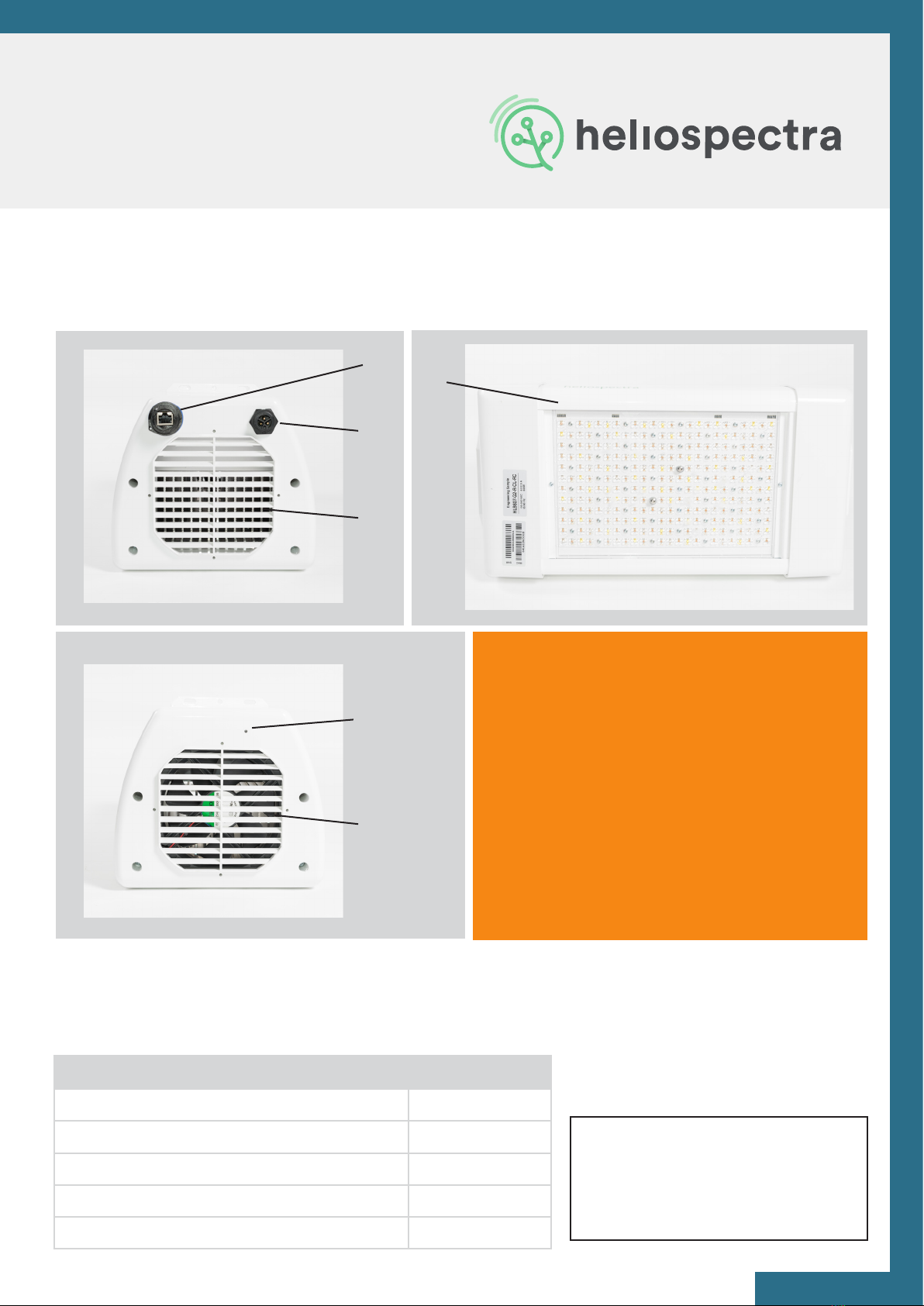
1.1 ELIXIA 600W Overview
Package Contents
1
2
3
4
5
6
1. Premounted DIN M6 I-Hooks
2. Ethernet Port
3. Power Socket
4. Heat Sink and Air Inlet
5. Status Indicator LED
6. Fan and Air Outlet
LEGEND
Description Quantity
Heliospectra ELIXIA 600W lamp unit 1
Premounted DIN M6 I-Hooks 2
2 m (6 ft 5 in) Power Cable 1
0.5 m (20 in) Ethernet Cable 1
Quick Setup Guide 1
NOTE!
When unpacking the ELIXIA make
sure to have a sturdy surface to
work on. Damage to the unit can
occur if dropped.
Before continuing with installation
verify that all parts in each ELIXIA
package have been received. If
any part is missing, contact your
customer service representative.
7www.heliospectra.com

1.2 ELIXIA 500W Overview
Package Contents
1
2
3
4
5
6
1. Premounted DIN M6 I-Hooks
2. Ethernet Port
3. Attached Power Cable
4. Heat Sink and Air Inlet
5. Status Indicator LED
6. Fan and Air Outlet
LEGEND
Description Quantity
Heliospectra ELIXIA 500W lamp unit with
attached 0.5 m (20 in) power cable
1
Premounted DIN M6 I-Hooks 2
0.5 m (20 in) Ethernet Cable 1
Quick Setup Guide 1
NOTE!
When unpacking the ELIXIA make
sure to have a sturdy surface to
work on. Damage to the unit can
occur if dropped.
Before continuing with installation
verify that all parts in each ELIXIA
package have been received. If
any part is missing, contact your
customer service representative.
8www.heliospectra.com

1.3 DYNA Series Overview
Package Contents
1
2
3
4
5
6
1. Premounted DIN M6 I-Hooks
2. Ethernet Port
3. Power Socket
4. Heat Sink and Air Inlet
5. Status Indicator LED
6. Fan and Air Outlet
LEGEND
Description Quantity
Heliospectra DYNA lamp unit 1
Premounted DIN M6 I-Hooks 2
2 m (6 ft 5 in) Power Cable 1
0.5 m (20 in) Ethernet Cable 1
Quick Setup Guide 1
NOTE!
When unpacking the DYNA make
sure to have a sturdy surface to
work on. Damage to the unit can
occur if dropped.
Before continuing with installation
verify that all parts in each DYNA
package have been received. If
any part is missing, contact your
customer service representative.
9www.heliospectra.com

2. Installation
2.1 Installation Requirements
Heliospectra AB requires that the xtures are installed with adequate surge protection according
to the IEEE 1100-2005 recommended practice for Powering and Grounding Electronic Equip-
ment.
Considering that surges can originate from both internal and external sources, SPDs should
be installed to provide maximum protection regardless of the source location. The three zones
include:
• The rst zone is at the service entrance where the most robust SPD is placed to divert
surges coming from external sources such as lightning. SPDs installed here are listed as
Type-1, SPD devices.
• The second zone of protection is within the facility at locations identied as susceptible
to surges. SPDs at these locations are listed as Type-2, SPD devices and are installed on
equipment such as switchboards, panelboards, motor-control centers.
• The third zone of protection is at the outlet or point of use. SPDs installed here are listed
as Type-3, SPD devices.
It is strongly recommended that a professional engineer, experienced with surge suppression
technology, be retained to design the protection system for your facility to ensure all SPDs are
properly sized and coordinated.
Heliospectra AB requires that the installation is conducted by a locally licensed electrician or
electrical engineer according to local electrical standards. This manual lists specic surge
protection requirements for North America and Europe, for other installation locations, please
advise local electrical standards that are equivalent.
Surge Protection Requirements - North America
10 www.heliospectra.com

Heliospectra AB requires that all xtures should be protected by adequate surge protection, in
accordance with the following standard: IEC 62305 – Protection Against Lightning.
This standard stipulates the following:
• SPDs (Surge Protection Devices) should be installed when crossing from one lightning
protection zone to another
• Lightning is not the only threat; switching of loads, which are more frequent than
lightning strikes, also create high voltage transients that can damage electrical or
electronic equipment over time
• Risk assessments are required to be carried out to assess the requirements of any
building for SPDs
• Ensure that the 3 Lightning Protection Zones (LPZ) zones and types 1, 2, 3 of Surge
Protection Devices are used correctly
Selecting the correct SPD equipment for a given application can be complex and Heliospectra
AB therefore advises that certied electrical engineering contractors and electricians are con-
sulted.
Surge Protection Requirements - Europe
11www.heliospectra.com
2.2 Mounting
For proper operation, the xture must be mounted horizontally from a support structure. The
support structure needs to be sturdy enough to support the weight of lamps and any additional
equipment. It must also allow for air to ow freely into the unit (an additional fan duct is avail-
able upon request; contact your Heliospectra sales representative for more information).
NOTE! Verify that the air inlet (4) and outlet (6) are not covered and that air is allowed to ow
freely around the unit. Otherwise, overheating may occur and cause the unit to dim to counter-
act heat buildup.
Follow the instructions to mount the xture:
1. The light is delivered with premounted M6 i-hook bolts (1); gure on page 3. Verify that
the bolt goes approximately 6 mm into the mounting holes and do not use excessive
force when tightening the bolts. Connect the eyelets in the bolts to chosen mounting
structure.
2. If other mounting hardware is used make sure that the bolts go all the way in the
mounting holes (6 mm).
3. Use chains or cables to suspend the lamp levelly from the support structure.
4. Verify that the unit is securely fastened.
5. Connect the supplied Ethernet cable to the Ethernet port (2).
6. Connect the Ethernet cable to a free port in the switch (see Example Setup for more
information).
ELIXIA 600W & DYNA ELIXIA 500W
7. To power up the lamp, connect
the supplied power cord to the
power socket (3), and then
connect the cord to a grounded
120V/230V, 50/60Hz power outlet.
7. The LX50 is a high voltage
industrial xture. The installation
must be conducted by a licensed
proffesional. The xture comes
with a 3 wire xed 0.5 m (20 in)
power cable.
12 www.heliospectra.com

NOTE! If the indicator LED does not ash green after 60 seconds, verify that all cables are se-
curely attached and that the unit and switch are powered on. Also verify that DHCP is enabled
in your network. If the problem persists, power cycle the lamp by removing and reinserting the
power cable.
NOTE! For proper performance of the unit the ambient air temperature shall be no higher than
40 °C (104 F).
A duct attachment allows for separating the cooling air from the plant growth environment. No
more than two lamps may be connected in series. The cooling air of the rst lamp shall have a
temperature of no more than 21 °C (70 F). (Air ducts are sold separately)
9. Repeat steps 1–8 to mount additional lamp units.
8. The indicator LED (5) (see Error! Reference source not found) will ash orange for
approximately 15 seconds and then ash green. The lamp unit is now ready for use.
13www.heliospectra.com

2.3 Air Flow
2.4 Network Setup
Every Heliospectra xture has a built in fan to cool the lamp when needed. When connecting
the xture to an air duct it is important that the air blows in the same direction as the built in
fan. The gure below shows that air is sucked in on the power connector side and pushed
through the Indicator LED side.
By default, the Heliospectra controllable lamp uses the Dynamic Host Conguration Protocol
(DHCP) to automatically receive an IP address from a router in the network. This is a commonly
available feature in computer networks. The IP address is used when conguring and monitor-
ing the lamp, see chapter 5 Lamp Conguration. A lamp can also be congured to use a static
IP, see section 3.3 Static IP Conguration.
If the airow through the lamp is restricted or the ambient temperature is too high the xture
may not be able to cool itself sufciently. If the internal temperature of the lamp becomes too
high the light will dim and icker and nally shut off to prevent damaging the lamp.
The protective mechanism is triggered at different stages depending on which components
risk overheating. In general, an internal temperature above 70°C (160F) or an ambient air tem-
perature above 50°C (120F) when running the xture at full power will trigger the protective
mechanism.
Over Temperature Protection
14 www.heliospectra.com
Power
connector
Fan
Indicator
LED
Plate temperature
sensor
Power supply
2.4.1 Example Setup
If it is vital that each lamp always is assigned the same IP address, consider using DHCP and
MAC address reservation (refer to your router documentation for more information how to
setup static DHCP addresses).
If unsure whether your network supports DHCP or if to use static IP address conguration, con-
tact your local network administrator.
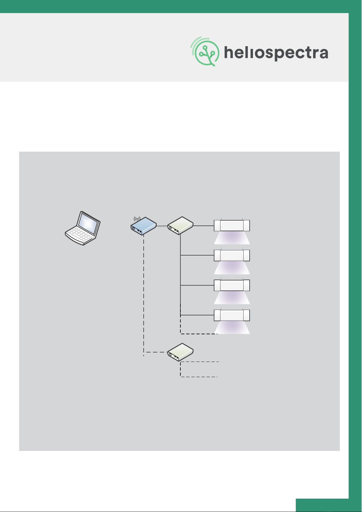
In the example setup each area or bench is placed some distance apart. Therefore, each set
of lamps is connected to a different switch. Each lamp in the example has been assigned a
unique IP address via DHCP in the private 192.168.1.X range. The switches are in turn connect-
ed to a wireless router. A control computer is used to connect to the wireless router to access
lamps for conguration and monitoring purposes.
When setting up several lamp units it is recommended to assign them to a dedicated network
that is not shared with normal ofce equipment or similar. An example lamp network is shown
in Figure 4 Network Example Setup:
Computer
Switch
192.168.1.110
192.168.1.111
192.168.1.112
192.168.1.113
Switch
Lamps over
bench 2
Wireless
Router
LX60
LX60
LX60
LX60
15www.heliospectra.com

Several variants of this setup are possible, for example:
• The areas are placed close together, allowing fewer switches with more ports to be used
to connect lamps to the router.
• A wired router is used with a stationary computer acting as control.
NOTE! If unsure of how to setup lamps in your network, contact your local network
administrator.
2.4.2 Recommended Network Devices
The following devices have successfully been used for setting up a network of lamps, but any ge-
neric router and switch supporting DHCP and 100 Mbit/s works with the Wi connected Lights:
• Small Installation (Less than 25 xtures)
Switches from the FS105/108/116 and GS105/108/116 NETGEAR® series
• Mid to Large Installations (More than 25 xtures)
Wireless router EdgeRouter from Ubiquiti with Ubiquity UAP-AC-M access points.
Each UAP-AC-M access point services up to 250 Heliospectra xtures.
16 www.heliospectra.com

2.4.3 General Router Setup Guide
1. Connect an ethernet cable between your computer (network-port) and your router
(any of the LAN-ports).
2. Access the router with your computer. To do this, open any web-browser and type in the
routers IP-address in the address eld (a common IP address for routers is: 192.168.1.1).
3. Now nd “Wireless Settings”. Here you should be able to alter the settings of your router
such as the router name (SSID), password, channel and security options.
4. Start by giving your network a name.
5. Choose your region.
6. Choose channel (do not choose automatic channel selection, as this is not supported by
the light). If you are uncertain what channel to choose: Check the country frequency
legislation regarding which channels are allowed. An easy way to check how all WIFI-net
work channels look like in your area, is to use the app “WIFI-analyzer” (freeware).
7. Choose “WPA2-PSK [AES]” under “Security Options”.
8. Choose a personal password for your network.
2. Navigate yourself to the WIFI settings in your routers web user interface.
3. Now settheSSIDto“HelioCong”,thepasswordto“Conf5600K”and choose the region
in which your lights are located in the world (geographically). NOTE: it is vital that you
type in these exact numbers and letters correct including capitals to make your lights nd
the router wirelessly.
4. Click “Apply” to save.
5. Now the setup of your router is done.
1. Go to the tab “Advanced” and type in an IP-range which covers the number of lights you
have in your network (plus possible other equipment such as printers and computers).
Example
We have set the IP-range between 192.168.1.2 (“Starting IP Address”) and 192.168.1.99 (“Ending
IP Address”). This means the router will deliver IP to maximum of 98x devices (devices = lights,
computers, printers etc.). Make sure to set this range so that it covers the full amount of lights
you have plus other equipment.
2. Save your settings. If you have done everything correctly, now your router will assign IP
addresses to your lights, so that they have addresses and are easily accessible through a
web browser or the Heliospectra’s software “System Assistant”.
Step 1 - Router Settings
Step 1 - Router Settings
Step 2 - Set IP Range
17www.heliospectra.com

3. Heliospectra
System Assistant
The Heliospectra System Assistant is an administrative standalone tool for the Heliospectra
controllable lights, enabling easy identication of and access to conguration and monitoring
functions of individual lamps in the network. The tool is also used for setting static IP to and
upgrading lamp rmware.
3.1 Setup
First verify the following:
• Lamps are correctly installed and running on a dedicated network.
• The control computer is running Microsoft Windows XP/Vista/Windows 7/Windows 8®
and is connected to the lamp network.
Steps to setup System Assistant
1. Retrieve System Assistant from the support section at www.heliospectra.com or
request it from your Heliospectra representative. Save the le to your control computer.
The System Assistant is a self-contained executable le so nothing has to be installed.
2. Double-click the Heliospectra System Assistant le and verify that the application starts.
It is recommended to create a shortcut to the System Assistant le and place it on the
desktop.
NOTE! If the control computer does not have Internet access, download the executable le to
another computer and transfer it to the control computer with an USB pen drive.
NOTE! The Heliospectra System Assistant needs access to the network. Verify that no rewall
is blocking trafc to or from the tool.
18 www.heliospectra.com
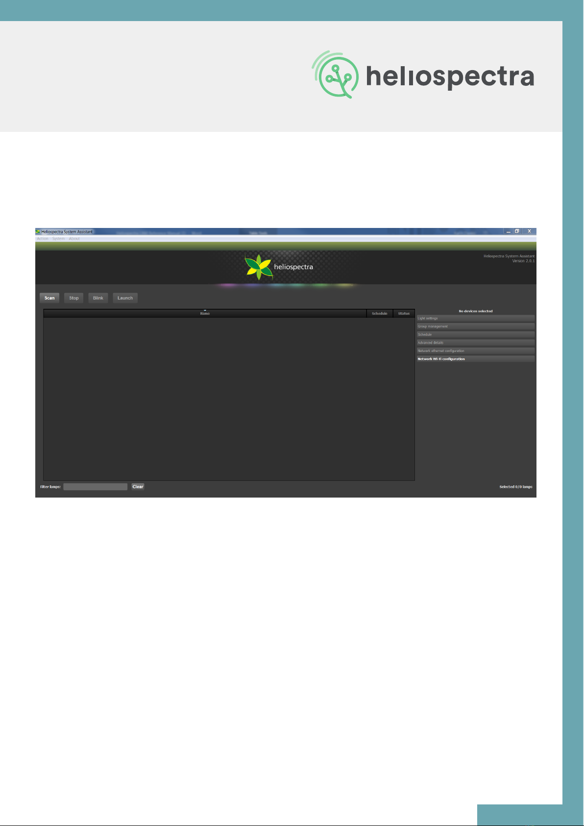
3.2 Using System Assistant
The main window contains the following general functions and information:
• The Action menu contains the Scan, Blink and Launch actions.
These actions are also accessible by clicking the Scan, Blink or Launch buttons.
• The System menu contains the following menu options:
o The Settings option covers lamp blink and scan conguration.
o The Update system option is used for updating the rmware in one or several
lamps.
o The Changeconguration option allows for setting the network conguration of
a lamp.
• The About menu contains version information of Heliospectra System Assistant and
where to nd more information.
• The lamp list eld shows the lamp on the network with detailed information about each
lamp (Name, MAC and IP address, Assignment, Mode, Schedule, Firmware version and
Status).
• Select lamps by clicking on a row in the lamp list. To select multiple lamps, hold the Ctrl
key pressed while selecting.
19www.heliospectra.com

3.2.1 Lamp Identication
3.2.2 Accessing the Web User Interface
Follow the instructions to identify a lamp in the network:
1. Start the Heliospectra System Assistant from the control computer.
2. Click Scan.
A list of available lamps on the network is shown.
3. Select row of the lamp to identify.
4. Click Blink.
5. The LEDs of the selected lamp will blink, enabling identication.
The LX60 lamp is congured and monitored through its Web User Interface (web UI).
Follow the instructions to access the web UI for a lamp:
1. Start the Heliospectra System Assistant from the control computer.
2. Click Scan. A list of available lamps on the network is shown.
3. Select the row of a lamp to congure or monitor.
4. Click Launch.
5. A web browser window with the chosen lamp web UI will open. For more information
about lamp conguration options, see chapter 4 Lamp Conguration.
NOTE! It is recommended to clearly label each lamp for future reference.
20 www.heliospectra.com
Other manuals for ELIXIA
1
This manual suits for next models
1
Table of contents
Other Heliospectra Lawn And Garden Equipment manuals


Popular Lawn And Garden Equipment manuals by other brands


Connected Essentials
Connected Essentials CEP-30 user manual

Smithco
Smithco Sand Star I Operator's manual

Alemlube
Alemlube SA300 owner's manual

Stihl
Stihl HTA 50.0 instruction manual

Toro
Toro 100 Series Z Master installation instructions

Creekvine Designs
Creekvine Designs Treated Pine 4x8 Cedar Inline Pergola manual