Heliospectra MITRA X User manual

User Manual
MITRA X
Heliospectra
Horticulture
Fixtures

www.heliospectra.com
2
Disclaimer
Copyright and
Trademarks
The contents of this document are subject to revision without notice, due to continued
progress in methodology, design and manufacturing. Heliospectra AB shall have no liability
for any error or damage resulting from the use of this document.
At Heliospectra AB we aim to continuously improve our product documentation. If you have
comments or ideas regarding this document, please contact us at
support@heliospectra.com
No part of this publication may be reproduced, stored in a retrieval system or transmitted in
any form or by any means, electronic, mechanical, photocopying, recording or otherwise, with-
out prior permission of Heliospectra AB.
©2011–2022 by Heliospectra AB. All rights reserved.
MITRA X User Manual Version 1.0 Published 2022-08-29

MITRA X User Manual
V.1.0 3
Precautions
When unpacking the luminaire make sure to have a sturdy surface
to work on. Damage to the unit can occur if dropped.
Do not immerse the xture in water or clean the xture with a
high-pressure water jet or strong detergents.
Never operate the xture with the LED board directly on a
at surface (e.g. table) as this may damage the LED board. A
minimum distance of 0.2m/8in should be kept to other objects.
The product is for indoor use only.
Always allow a free ow of air around the xture. A minimum
distance of 0.2m/8in should be kept to other objects. Blocked
airow might overheat and damage the xture.
This xture may only be serviced by a trained technician. In the
case of a suspected malfunction contact your distributor or
Heliospectra directly.
The light source contained in this luminaire shall only be replaced
by the manufacturer or his service agent or a similar qualied
person.
The luminaire should be positioned so that prolonged staring
into the luminaire at a distance closer than 1 meter/ 40 inches is
avoided.
Do not stare into the light source. LED grow lights may contain
potentially harmful light radiation. Please use UV blocking eyewear
when working in and around the illuminated area.
Only connect the xture to properly grounded mains that complies
with the voltage rating on the xture (see power label).
Only operate the xture with an undamaged power cord, power
plug and electrical outlet.
Never unplug the xture by pulling on the power cord.
For proper performance of the unit the ambient air temperature
shall be no higher than 45° C.
Quand vous déballez le luminaire, assurez-vous d’avoir une
surface solide sur laquelle travailler. L’appareil peut être
endommagé si on le fait tomber.
N’immergez pas l’appareil dans l’eau et n’essayez pas de le
nettoyer avec un jet d’eau à haute pression ou avec des produits
détergents.
Ne pas mettre en marche le luminaire lorsque la platine LED est
posée à plat sur quelconque surface (par exemple : une table),
cela pourrait endommager la platine LED. Respectez une distance
minimum de 0,2 m/8 po entre l’appareil et les autres objets.
Le produit ne s’utilise qu’en intérieur.
Assurez-vous qu’il y ait un minimum d’air autour de l’appareil.
Respectez une distance minimum de 0,2 m/8 po entre l’appareil
et les autres objets. Le blocage de la circulation de l’air pourrait
causer une surchauffe et endommager l’appareil.
Cet appareil ne peut être entretenu que par un technicien
expérimenté. Si vous avez un doute sur le bon fonctionnement de
celui-ci, contactez votre distributeur ou Heliospectra directement.
La source de lumière contenue dans ce luminaire ne doit-être
remplacée que par le fabricant, ses agents de services ou une
personne également qualiée pour le faire.
Le luminaire doit être positionné de telle sorte qu’il soit impossible
de le xer longuement à une distance de un mètre/40 pouces soit
évité.
Ne pas regarder xement la source de lumière. Les éclairages LED
pourraient potentiellement contenir des radiations lumineuses
nocives. Portez des lunettes anti-rayons UV quand vous travaillez
sous ou à proximité de l’endroit éclairé.
Ne connectez l’appareil que sur une prise reliée à la terre et dont la
tension correspond à celui de l’appareil (voir l’étiquette concernant
la puissance).
L’appareil doit être uniquement mis en marche avec une prise, un
cordon électrique ou une prise secteur en bon état.
Ne jamais déconnecter l’appareil en tirant sur le cordon électrique.
Pour une utilisation optimale de l’appareil, la température
ambiante ne doit pas dépasser 45 °C.
Our product is an advanced and safe LED
luminaire. However, for proper operation and
for your safety, please read and follow the be-
low precautions:
Le produit est un appareil à LED moderne
et sûr. Néanmoins pour l’utiliser correctement
et en toute sécurité, veuillez lire les informa-
tions ci-dessous:

www.heliospectra.com
4
Table of Contents
1. PRODUCT OVERVIEW ...............................................................................................
2. MITRA X (MI65XR40, MI65XR40F, MI65XR60, MI65XR60F, MI65XR80) ....................
2.1 Physical Overview ............................................................................................
2.2 TechnicalSpecications......................................................................................
2.3 Output and Spectrum ........................................................................................
3. PSU FLEX (MIPSU05, MIPSU06, MIPSU07, MIPSU08)...........................................
3.1 Physical Overview ................................................................................................
3.2 TechnicalSpecications..................................................................................
4. MOUNTING KITS .......................................................................................................
4.1 MITRA X Chain-Bracket Kit (MIKIT01) ...............................................................
4.2 MITRA X C-Bracket Kit (MIKIT02) .......................................................................
5. MOUNTING INSTRUCTIONS.......................................................................................
5.1 MITRA X ..............................................................................................................
5.2 PSU Flex .............................................................................................................
6. ELECTRICAL INSTALLATION .......................................................................................
6.1 Lamp Connection ..................................................................................................
6.2 Power Connection ...............................................................................................
6.2.1 Surge Protection .....................................................................................
6.3 Dimming Connection ...........................................................................................
6.3.1 Dimming Using 0-10VDC Signal ..............................................................
6.3.2 Dimming Using 10V PWM Signal.............................................................
7. MAINTENANCE ..........................................................................................................
7.1 Cleaning ............................................................................................................
7.2 Disposal .............................................................................................................
8. GENERAL WARRANTY TERMS AND CONDITIONS ................................................
8.1 Warranty ..........................................................................................................
8.2 Terms and Conditions ......................................................................................
8.2.1 Electrical Installation Quality Requirements and Conditions ................
8.2.2 Surge Protection Requirements ........................................................
8.2.3 Warranty Limitations ............................................................................
8.2.4 Warranty Claim Process ......................................................................
8.3 Implied or Other Warranties ................................................................................
8.4 Disclaimers .....................................................................................................
6
7
7
8
9
10
10
11
13
13
13
14
15
16
17
17
17
18
19
20
20
21
21
22
23
23
24
24
24
25
26
28
28

MITRA X User Manual
V.1.0 5

www.heliospectra.com
6
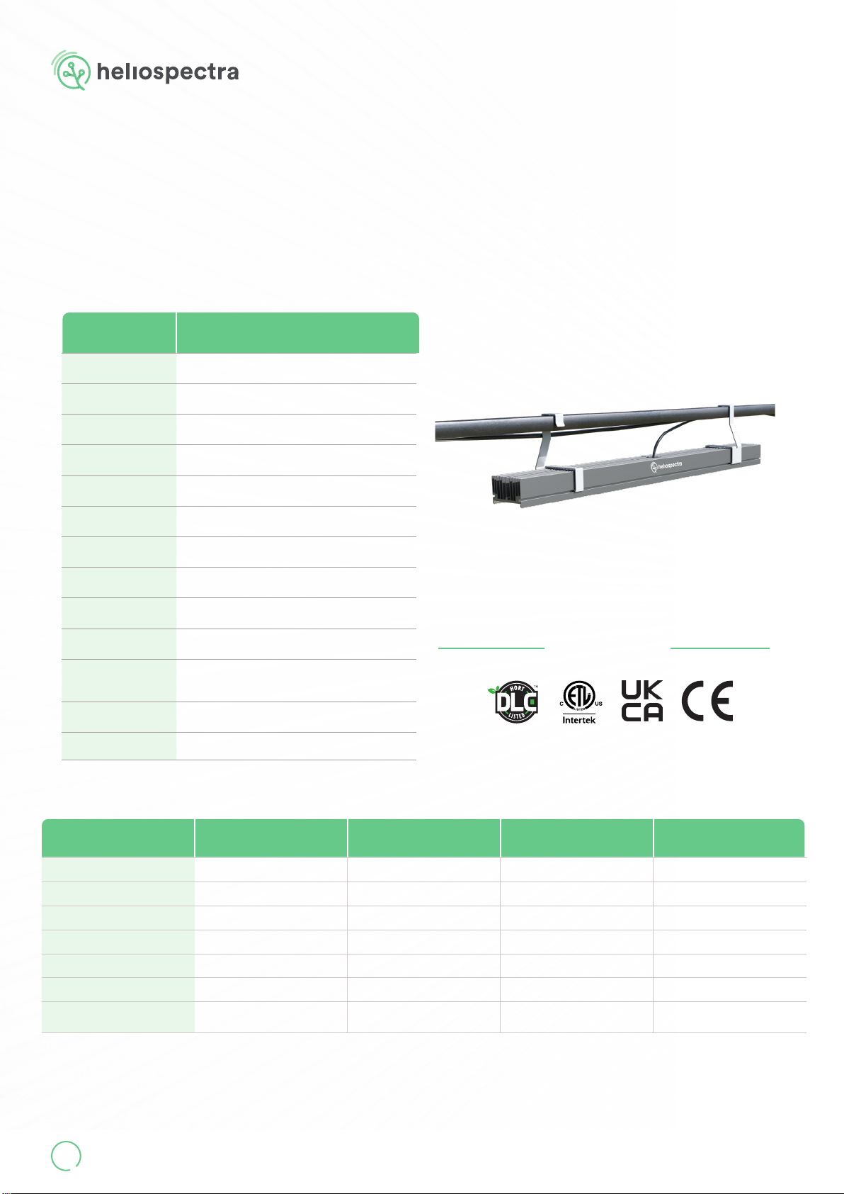
1. Product Overview
MOUNTING KITS
PRODUCT CODE MOUNTING KIT
MIKIT01 MITRA X Chain-Bracket Kit
MIKIT02 MITRA X C-Bracket Kit
Mounting Kit
Lamp
Power Supply Unit
MITRA X - COMPLETE FIXTURES
PRODUCT CODE LAMP POWER SUPPLY UNIT
MI65XR40-05 MITRA X - MI65XR40 PSU Flex - MIPSU05
MI65XR40-06 MITRA X - MI65XR40 PSU Flex - MIPSU06
MI65XR40F-05 MITRA X - MI65XR40F PSU Flex - MIPSU05
MI65XR40F-06 MITRA X - MI65XR40F PSU Flex - MIPSU06
MI65XR60-05 MITRA X - MI65XR60 PSU Flex - MIPSU05
MI65XR60-06 MITRA X - MI65XR60 PSU Flex - MIPSU06
MI65XR60F-05 MITRA X - MI65XR60F PSU Flex - MIPSU05
MI65XR60F-06 MITRA X - MI65XR60F PSU Flex - MIPSU06
MI65XR80-07 MITRA X - MI65XR80 PSU Flex - MIPSU07
MI65XR80-08 MITRA X - MI65XR80 PSU Flex - MIPSU08
MITRA X xtures consists of a lamp, a power supply unit and a mounting kit.
NOTE!
When unpacking and installing your MITRA X make sure to have a sturdy surface to work on.
The xture may get damaged if dropped.
MITRA X User Manual
V.1.0 7
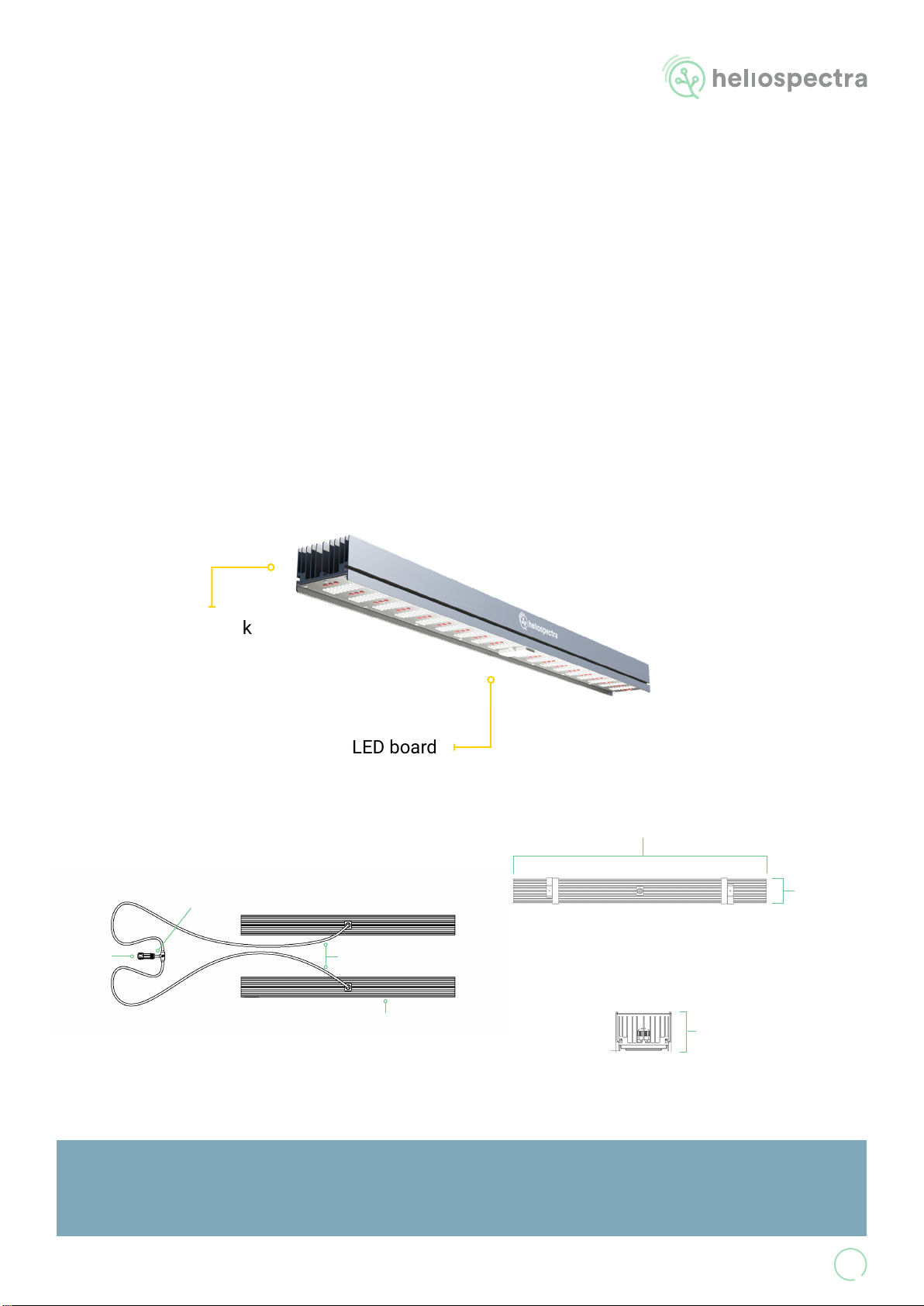
LED board
1040 mm / 41 in
66 mm / 2.6 in
96 mm / 3.8 in
Top View
Front View
Maximum distance between Lamp Modules: 3.4m (11.2 ft).
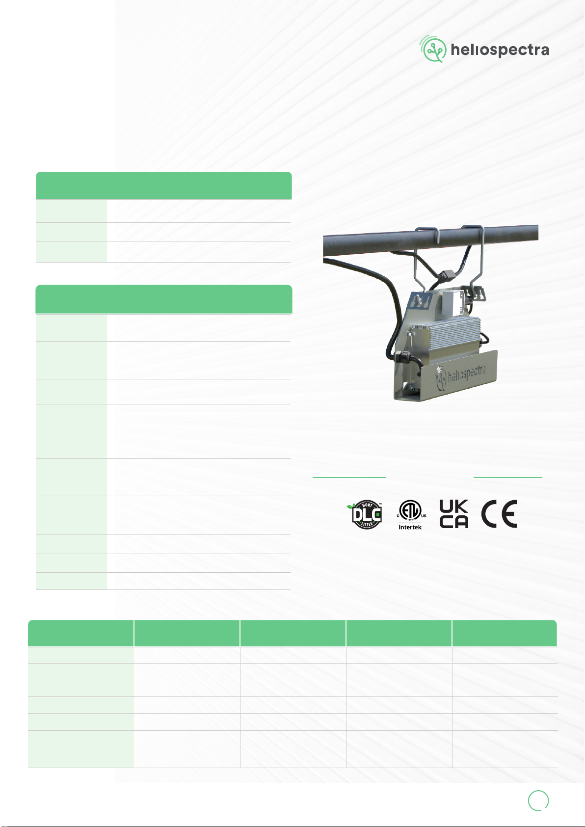
2.1 Physical Overview
Heat sink
Lamp Module
PSU
Connector Cable 1.8 m / 70.9 in
Cable 0.1m / 3.9in
2. MITRA X
(MI65XR40, MI65XR40F, MI65XR60, MI65XR60F, MI65XR80)
MITRA X lamps consists of two lamp modules connected by a cable tree.
www.heliospectra.com
8
2.2 Technical Specications
PHYSICAL MI65XR40, MI65XR40F, MI65XR60,
MI65XR60F, MI65XR80
Weight 8.8 kg (19.5 lbs)
Measurements 1040 x 96 x 66 mm | 41 x 3.8 x 2.6 in
(LxWxH)
Mounting Chain-bracket* or C-bracket*
Temperature Operating: -10-45°C (14-113°F)
Storage: -20-70°C (-4-158°F)
Humidity 10-95% RH
Heat Value (incl. PSU) Max: 2290 BTU/h
IP Rating IP66
Lifetime (Q90) >54 000 h
Cooling Passive - Convection cooled
Beam Angle 120°
Housing Material
Anodized aluminum heatsink
Highly transmissive silicone coating
SJOW cables and PA66 connectors
Compliance CE, UKCA, cETLus, and Damp Location
Warranty 5 years
* Requires the Adelphi wireless connector
ELECTRICAL MI65XR40-05, MI65XR40F-05,
MI65XR60-05, MI65XR60F-05
MI65XR40-06, MI65XR40F-06,
MI65XR60-06, MI65XR60F-06 MI65XR80-07 MI65XR80-08
PSU MIPSU05 MIPSU06 MIPSU07 MIPSU08
Input voltage range 100 - 277 VAC 277 - 480 VAC 100 - 277 VAC 277 - 480 VAC
Input current range 2.3 - 5.6 A 1.4 - 2.4 A 2.4 - 5.9 A 1.4 - 2.4 A
Frequency 50/60 Hz 50/60 Hz 50/60 Hz 50/60 Hz
Power factor > 0.98 > 0.97 > 0.96 > 0.97
THD < 10% < 10% < 10% < 10%
Dimming 0-10VDC, 10V PWM signal
or WiFi*
0-10VDC, 10V PWM signal
or WiFi*
0-10VDC, 10V PWM signal
or WiFi*
0-10VDC, 10V PWM signal
or WiFi*
CERTIFICATIONS
(Pending)
Data points are subject to change without notice. Tolerance +/- 10%
* Available as part of mounting kit
MITRA X User Manual
V.1.0 9
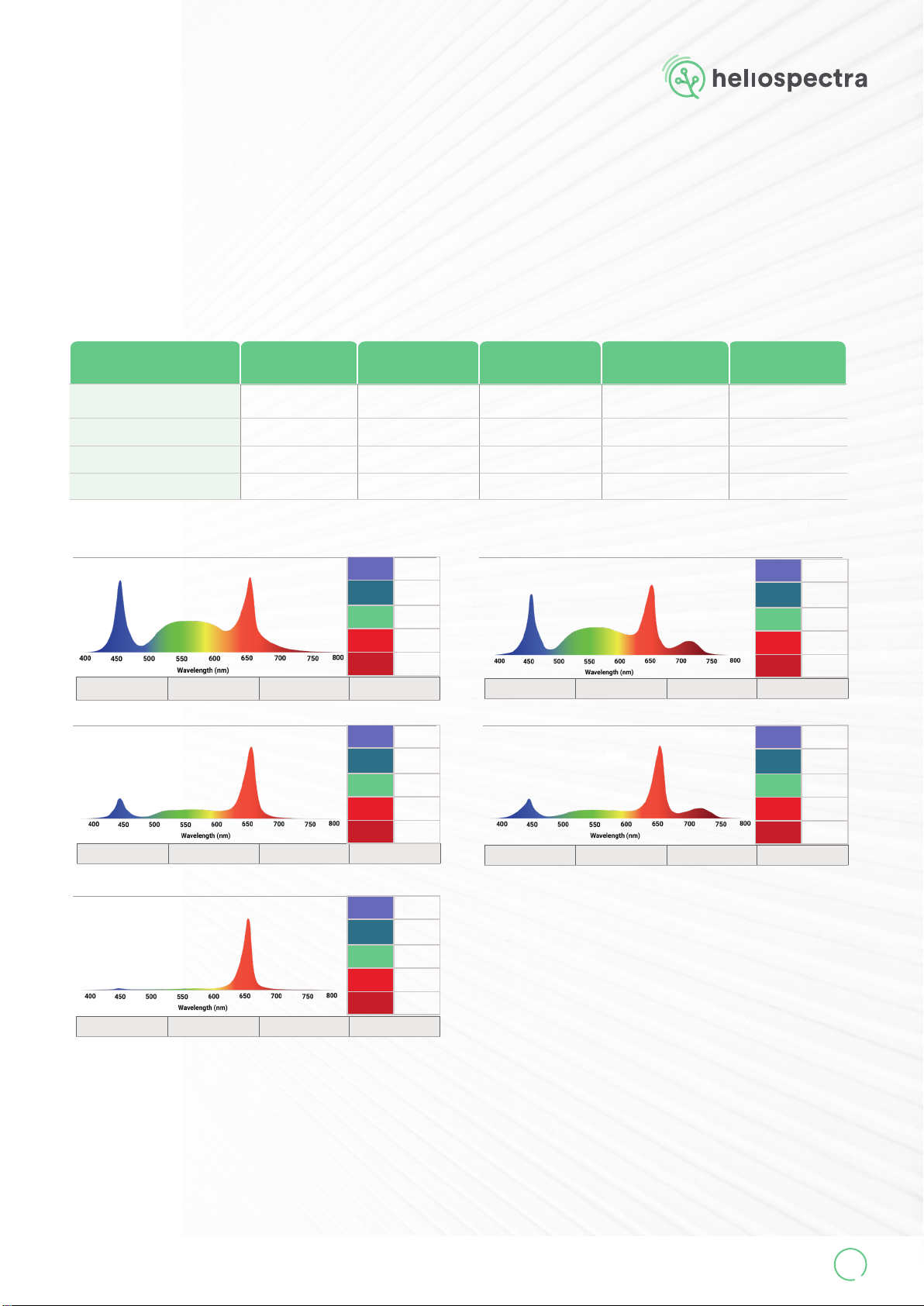
2.3 Output and Spectrum
OUTPUT helioSPEC R40 helioSPEC R40F helioSPEC R60 helioSPEC R60F helioSPEC R80
Products MI65XR40-05
MI65XR40-06
MI65XR40F-05
MI65XR40F-06
MI65XR60-05
MI65XR60-06
MI65XR60F-05
MI65XR60F-06
MI65XR80-07
MI65XR80-08
Power (W) 650 668 661 646 656
Light output (µmol/s) 1867 1957 2079 2002 2365
Ecacy (µmol/J) 2.9 2.9 3.1 3.1 3.6
CCT (K) 1289 CRI 28,1
CCT (K) 3981 CRI 65,3
CCT (K) 6244 CRI 80,8
CCT (K) 3736 CRI 62,5
helioSPEC R40 helioSPEC R40F
helioSPEC R60 helioSPEC R60F
helioSPEC R80
UVA 0%
Blue 24%
Green 37%
Red 38%
Far red 1%
CCT (K) 6067 CRI 80,4
UVA 0%
Blue 22%
Green 33%
Red 37%
Far red 9%
UVA 0%
Blue 16%
Green 24%
Red 59%
Far red 1%
UVA 0%
Blue 3%
Green 7%
Red 90%
Far red 1%
UVA 0%
Blue 13%
Green 20%
Red 56%
Far red 12%
Data points are subject to change without notice. Tolerance +/- 10%
www.heliospectra.com
10
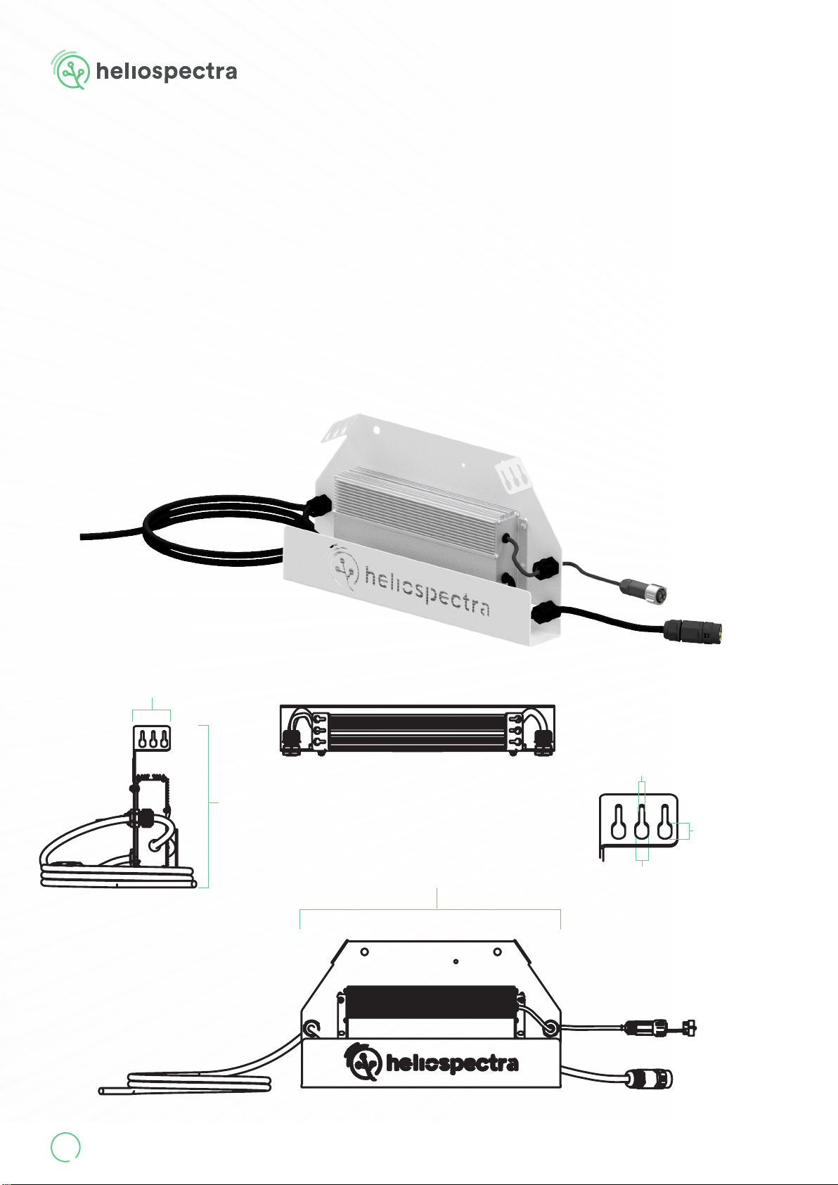
380 mm / 15 in
60 mm / 2.4 in
Side View
3.1 Physical Overview
Lamp Cable
130 mm / 5.1 in
Dimming Cable
210 mm / 8.3 in
Power Cable
2000 mm / 78.7 in
Front View
13.0 mm / 0.51 in
8.5 mm / 0.33 in
3.5 mm / 0.14 in
Chain Slot
Top View
3. PSU Flex
(MIPSU05, MIPSU06, MIPSU07, MIPSU08)
210 mm / 8.3 in
Protective
Lid
MITRA X User Manual
V.1.0 11
3.2 Technical Specications
PHYSICAL
Size 380 mm x 210 mm x 60 mm | 15.0 x 8.3 x 2.4 in
(L x W x H)
Weight 3.8 kg (8.4 lbs)
Mounting Chain or C-hook*
* Available as part of mounting kit
GENERAL
Temperature Operating: -10-45°C (14-113 F)
Storage: -20-70°C (-4-158 F)
Humidity 10-95% RH
IP Rating IP66, IP67
Lifetime MIPSU05, MIPSU07: 67 000 h
MIPSU06, MIPSU08: 50 000 h
Dimming
Input: 0-10VDC, 10V PWM signal (200-2000 Hz) or WiFi**
Connector: M19 Push Locking 4 Pin Female
AUX: 12V, max 200mA
Cooling Passive - Convection cooled
Housing Material
Powder coated aluminum bracket
Anodized aluminum PSU
SJOW cables and PA66 connectors
Cable Lenghts
Power cable: 2.0 m / 78.7 in
Lamp cable: 0.13 m / 5.1 in
Dimming cable: 0.21 m / 8.3 in
Plug-options Open ended
Compliance CE, UKCA, cETLus, and Damp Location
Warranty 5 years
ELECTRICAL MIPSU05 MIPSU06 MIPSU07 MIPSU08
Input voltage range 100 - 277 VAC 277 - 480 VAC 100 - 277 VAC 277 - 480 VAC
Input current range 2.3 - 5.6 A 1.4 - 2.4 A 2.4 - 5.9 A 1.4 - 2.4 A
Frequency 50/60 Hz 50/60 Hz 50/60 Hz 50/60 Hz
Power factor > 0.98 > 0.97 > 0.96 > 0.97
THD < 10% < 10% < 10% < 10%
Inrush Current
2.1 A²s at 220Vac input, 25°C
cold start, duration=14.2 ms,
10%Ipk-10%Ipk.
1.55 A²s at 220Vac input, 25°C
cold start, duration=14.2 ms,
10%Ipk-10%Ipk.
2.1 A²s at 220Vac input, 25°C
cold start, duration=14.2 ms,
10%Ipk-10%Ipk.
1.55 A²s at 220Vac input, 25°C
cold start, duration=14.2 ms,
10%Ipk-10%Ipk.
CERTIFICATIONS
(Pending)
** Requires the Adelphi wireless connector
Protective
Lid

www.heliospectra.com
12
ELECTRICAL
MIPSU05 MIPSU06 MIPSU07 MIPSU08
MI65XR40
Input voltage Input current | Power | PF Input current | Power | PF Input current | Power | PF Input current | Power | PF
100 VAC 5.48 A | 654 W | 0.99 ---
120 VAC 5.46 A | 651.2 W | 0.99 ---
220 VAC 2.94 A | 637.4 W | 0.99 ---
240 VAC 2.69 A | 636.4 W | 0.98 ---
277 VAC 2.34 A | 635.1 W | 0.98 2.35 A | 644.2 W | 0.99 - -
347 VAC -1.86 A | 640.8 W | 0.99 - -
400 VAC -1.63 A | 639.9 W | 0.98 - -
480 VAC -1.38 A | 639.7 W | 0.97 - -
MI65XR40F
Input voltage Input current | Power | PF Input current | Power | PF Input current | Power | PF Input current | Power | PF
100 VAC 5.64 A | 673.5 W | 0.99 ---
120 VAC 5.62 A | 670.6 W | 0.99 ---
220 VAC 3.02 A | 655.9 W | 0.99 ---
240 VAC 2.77 A | 655.0 W | 0.98 ---
277 VAC 2.41 A | 653.7 W | 0.98 2.42 A | 663.7 W | 0.99 - -
347 VAC -1.92 A | 659.8 W | 0.99 - -
400 VAC -1.67 A | 658.4 W | 0.99 - -
480 VAC -1.42 A | 657.2 W | 0.97 - -
MI65XR60
Input voltage Input current | Power | PF Input current | Power | PF Input current | Power | PF Input current | Power | PF
100 VAC 5.58 A | 666.8 W | 0.99 ---
120 VAC 5.56 A | 663.9 W | 0.99 ---
220 VAC 2.99 A | 649.5 W | 0.99 ---
240 VAC 2.75A | 649.0 W | 0.98 ---
277 VAC 2.39 A | 647.8 W | 0.98 2.40 A | 659.3 W | 0.99 - -
347 VAC -1.90 A | 655.6 W | 0.99 - -
400 VAC -1.66 A | 654.2 W | 0.99 - -
480 VAC -1.41 A | 653.2 W | 0.97 - -
MI65XR60F
Input voltage Input current | Power | PF Input current | Power | PF Input current | Power | PF Input current | Power | PF
100 VAC 5.45 A | 651.9 W | 1.00 -
120 VAC 5.43 A | 649.0 W | 1.00 ---
220 VAC 2.92 A | 634.4 W | 0.99 ---
240 VAC 2.68 | 633.7 W | 0.98 ---
277 VAC 2.33 A | 632.5 W | 0.98 2.34 A | 641.1 W | 0.99 - -
347 VAC -1.85 A | 637.6 W | 0.99 - -
400 VAC -1.62 A | 636.4 W | 0.99 - -
480 VAC -1.37 A | 636.1 W | 0.97 - -
MI65XR80
Input voltage Input current | Power | PF Input current | Power | PF Input current | Power | PF Input current | Power | PF
100 VAC - - 5.85 A | 645.5 W | 1.00 -
120 VAC - - 5.36 A | 643.2 W | 0.99 -
220 VAC - - 2.90 A | 631.7 W | 0.99 -
240 VAC - - 2.68 A | 631.3 W | 0.98 -
277 VAC - - 2.38 A | 630.8 W | 0.96 2.36 A | 647.5 W | 0.99
347 VAC ---1.87 A | 644.2 W | 0.99
400 VAC ---1.71 A | 643.4 W | 0.99
480 VAC ---1.39 A | 642.9 W | 0.97
Data points are subject to change without notice. Tolerance +/- 10%

MITRA X User Manual
V.1.0 13
4.1 MITRA X Chain-Bracket Kit
(MIKIT01) 4 pcs MITRA X Chain-bracket for
mountingaMITRAXxture.
The maximal chain diameter is
3 mm (0.12 in)
Product Code MIKIT01
Components 4 pcs MITRA
X Chain-brack-
et
Intended For* MI65XR40,
MI65XR40F,
MI65XR60,
MI65XR60F,
MI65XR80
Weight (1 pcs) 170 g (6 oz)
4 pcs MITRA X C-bracket for mounting a
MITRAXxture.
The inner width of the C-bracket is 42 mm
(1.65 in).
Total height Fixture + C-bracket: 200 mm
(7.8 in)
2 pcs PSU Flex C-hook for mounting a PSU
Flex.
The inner width of the C-hook is 42 mm
(1.65 in).
Total height PSU + C-hook: 310 mm (12.2 in)
Product Code MIKIT02
Component A 4 pcs MITRA X
C-bracket
Intended For* MI65XR40,
MI65XR40F,
MI65XR60,
MI65XR60F,
MI65XR80
Weight (1 pcs) 200 g (7 oz)
Component B 2 pcs PSU
Flex C-hook
Intended For* MIPSU05,
MIPSU06,
MIPSU07,
MIPSU08
Weight (1 pcs) 40 g (1.4 oz)
4.2 MITRA X C-Bracket Kit
(MIKIT02)
*NOTE: Do not use for mounting any other equpiment
13.0 mm / 0.51 in
8.5 mm
0.33 in
3.5 mm / 0.14 in
Chain Slot
4. Mounting Kits

NOTE!
Heliospectras recommendation for installations using chain:
• Welded chain with a diameter of 2-3 mm (1/16 - 1/8 in)
• Work load limit: Minimum 4 times the total weight of the equipment
www.heliospectra.com
14
The support structure needs to be sturdy enough to support the weight of the MITRA X lamp, the
power supply unit and any additional equipment. None of the power cables can be used to support
the weight of the xture.
Air must be able to ow freely around the MITRA X xture and power supply.
MITRA X is not suitable for intracanopy use.
5. Mounting Instructions
MITRA X User Manual
V.1.0 15
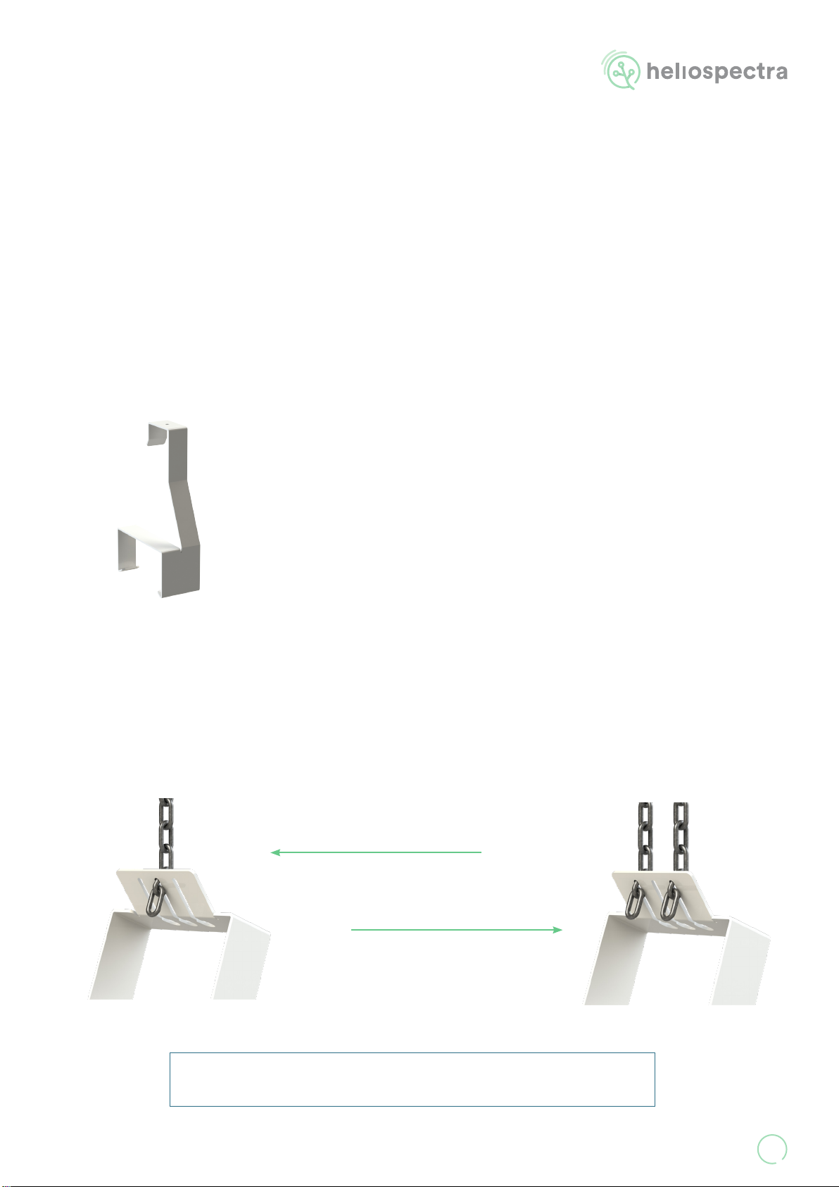
5.1 MITRA X
MITRA X xtures are compatible with the MITRA X Chain-Bracket Kit (MIKIT01) and the MITRA X
C-Bracket Kit (MIKIT02).
MITRA X lamps can be mounted with the Chain-brackets from MITRA X Chain-Bracket Kit
(MIKIT01). Use two Chain-brackets per lamp module to hang the xture using off-the-shelf chains.
The brackets should be placed so that they cover the markings on the heatsink. Make sure to select
a chain of such quality that it can support four times the load from the xture. The maximal chain
diameter is 3 mm (0.12 in).
One-point chain mounting
Two-point chain mounting
NOTE: Chains are not included.
For other mounting options, contact Heliospectra Support.
MITRA X lamps can be mounted with the C-brackets from MITRA X
C-Bracket kit (MIKIT02). Use two C-brackets per lamp module to mount
the xture from Unistrut proles or similar. Attach one C-bracket in each
direction (e.g. so that they are 180° rotated relative to each other) to
ensure that the lamp modules are level. The brackets should be placed
so that they cover the markings on the heatsink.
The inner width of the C-bracket is 42 mm (1.65 in).

www.heliospectra.com
16
5.2 PSU Flex
PSU Flex has a backplate which is prepared for
mounting with off-the-shelf chains. Make sure
to select a chain of such quality that it can sup-
port four times the load from the PSU.
The maximal chain diameter is 3 mm (0.12 in).
Note: Chains are not included.
One-point chain mounting. Two-point chain mounting.
PSU Flex can be mounted with the C-hooks
from MITRA X C-Bracket kit (MIKIT02). Use
two C-hooks per PSU to mount the unit from
Unistrut proles or similar.
The inner width of the C-hook is 42 mm
(1.65 in).
PSU Flex power supply units can be mounted directly by their backplate, and are also compatable
the MITRA X C-Bracket Kit (MIKIT02).

NOTE!
MI65XR80-07 and MI65XR80-08 comes with extra grounding cables connected to the heat-
sink. These grounding cables must be connected to the PSU backplate. Secure this connection
using the grounding screw on the PSU backplate.
NOTE!
All electrical installation should be done by a qualied electrician.
MITRA X User Manual
V.1.0 17
6. Electrical Installation
The PSUs lamp cable is equipped with a larger, black quick connector which should be connected to
the lamps PSU connector.
6.1 Lamp Connection
6.2 Power Connection
The PSUs input power cable is open ended with three internal cables:
MIPSU05, MIPSU07:
• Brown: Phase 1 / L
• Blue: Neutral / L
• Green/Yellow: Protective earth / ground
MIPSU06, MIPSU08:
• Brown: Phase 1 / L1
• Blue: Phase 2 / L2
• Green/Yellow: Protective earth / ground
www.heliospectra.com
18
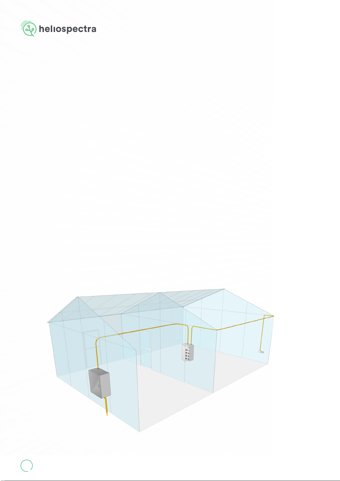
All installations should utilize surge protection devices (SPDs), to provide maximum protection
regardless of the source of the surge. The three zones include:
• The rst zone is at the service entrance where the most robust SPD is placed to divert surges
coming from external sources such as lightning. SPDs installed here are listed as Type-1, SPD
devices.
• The second zone of protection is within the facility at locations identied as susceptible to surg-
es. SPDs at these locations are listed as Type-2, SPD devices and are installed on equipment such
as switchboards, panel-boards, motor-control centers.
• The third zone of protection is at the outlet or point of use. SPDs installed here are listed as
Type-3, SPD devices.
It is strongly recommended that a professional engineer, experienced with surge suppression
technology, be retained to design the protection system for your facility to ensure all SPDs are
properly sized and coordinated.
Third zone
First zone
Second zone
6.2.1 Surge Protection
Heliospectra AB requires that the xtures are installed with adequate surge protection according
to the local recommended practice. In North America IEEE 1100-2005 contains the recommended
practice for powering and grounding electronic equipment. In Europe the applicable standard is IEC
62305 – Protection Against Lightning. If you are outside of North America or Europe please use your
local standard.
MITRA X User Manual
V.1.0 19
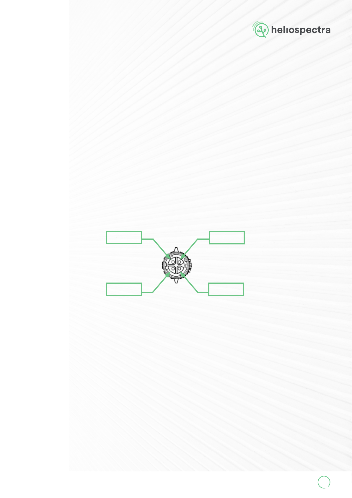
6.3 Dimming Connection
The dimming cable has a black quick connector to be connected to your preferred dimming solu-
tion.
The dimming connector comes with a protective cap. Remove the cap before connecting to your
preferred dimming solution. Leave the cap on if the dimming connector is not used.
The power supply unit supports 0-10VDC dimming or 10V PWM signal (200-2000 Hz) dimming.
The AUX supplies 12VDC, max 200 mA. The power supply is compatable with the Adelphi Wireless
Connector.
DIM+ DIM-
AUX+ AUX-
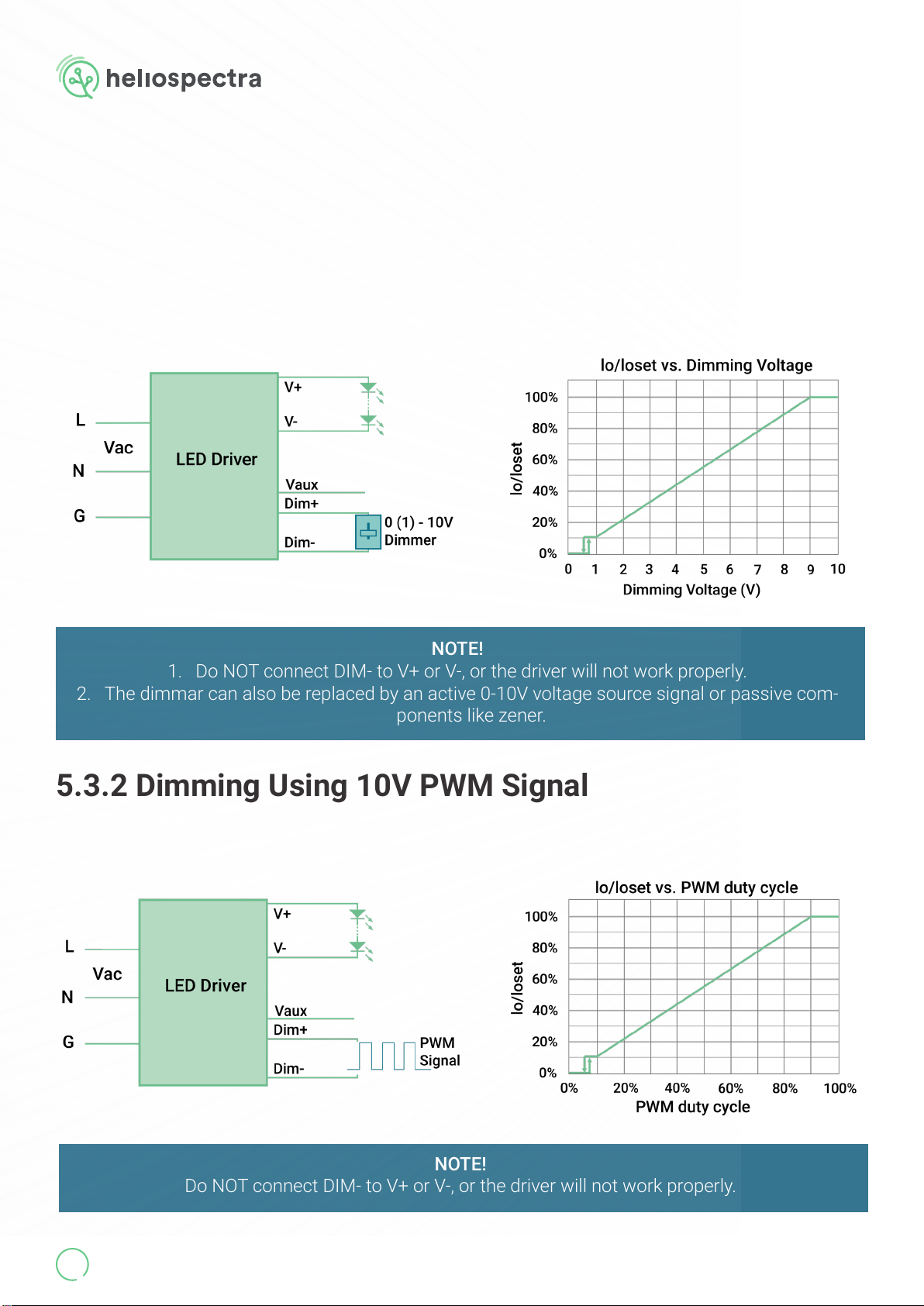
NOTE!
1. Do NOT connect DIM- to V+ or V-, or the driver will not work properly.
2. The dimmar can also be replaced by an active 0-10V voltage source signal or passive com-
ponents like zener.
5.3.2 Dimming Using 10V PWM Signal
NOTE!
Do NOT connect DIM- to V+ or V-, or the driver will not work properly.
www.heliospectra.com
20
The recommended implementation of the 0-10VDC dimming control is provided below.
The recommended implementation of the 10V PWM signal dimming control is provided below.
6.3.1 Dimming Using 0-10VDC Signal
Table of contents
Other Heliospectra Lawn And Garden Equipment manuals


Popular Lawn And Garden Equipment manuals by other brands


EMGA
EMGA Mo-el 505.350 Use and maintenance

Parkside
Parkside 331856 1907 instruction manual

ZappBug
ZappBug Oven owner's manual

Millcreek
Millcreek 406 Operator's manual

Montgomery Ward
Montgomery Ward ZYJ-290C Owner's guide and parts list

Hyundai power products
Hyundai power products HYSC210 instruction manual

New Holland
New Holland HT152 Specifications

Tiger
Tiger MAXXUM 110 operating instructions

General Pipe Cleaners
General Pipe Cleaners speedrooter 91 operating instructions

Snapper
Snapper 82597 Safety instruction & operatorrs manual

Nakayama
Nakayama BS4000 owner's manual

Zenoah
Zenoah BCZ260L Operator's manual