8
Caution! To avoid a lost of sound pressure make sure that
the crossover frequencies of high- and lowpass are sepa-
rated of 2 octaves when building a bandpass.
That means: If the lowpass signal is adjusted to 320 Hz the hig-
hpass should be adjusted 2 octaves lower on approx. 80 Hz. (1
octave = double frequency or half frequency)
If a subwoofer is connected we recommend to use high-
pass control 10 as variable subsonic filter or turn it
counter-clockwise to 15 Hz to get a subsonic filter.
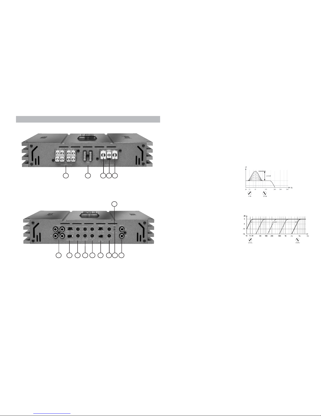
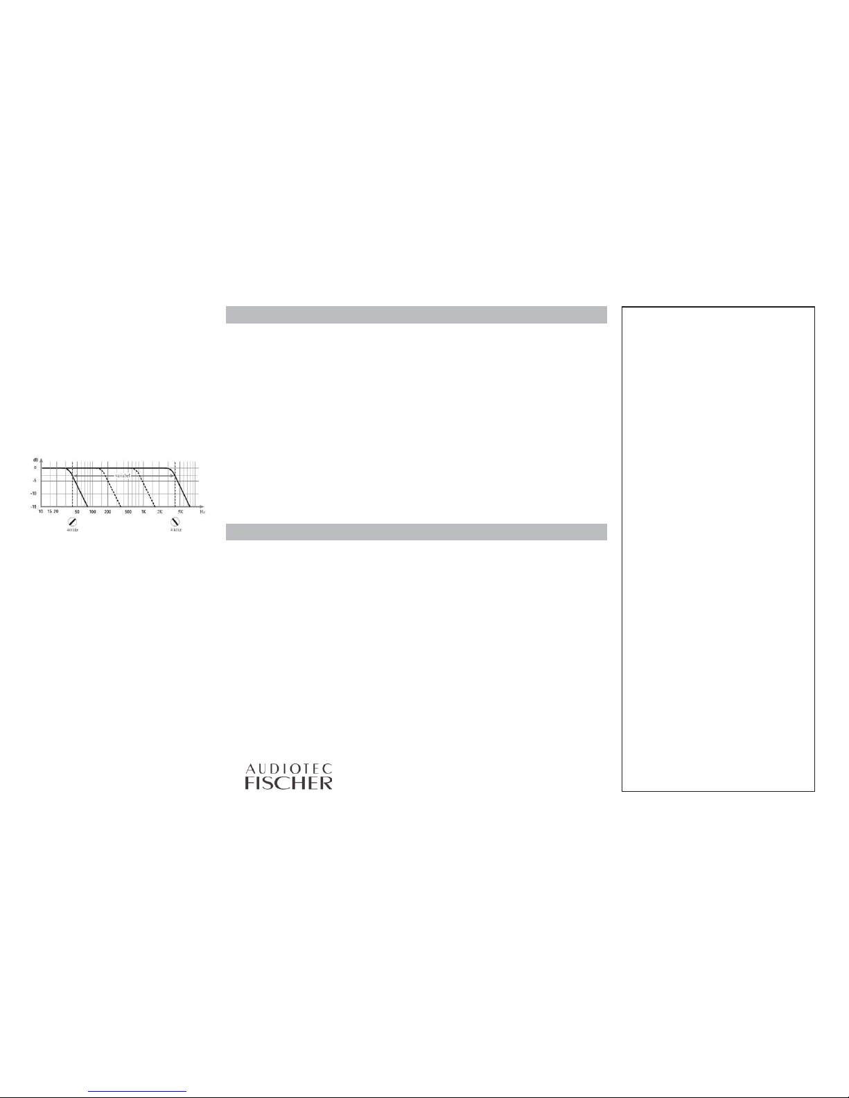
12 Lowpass control
To adjust the crossover frequency from 40 Hz to 4000 Hz
Lowpass: 40 - 4 kHz
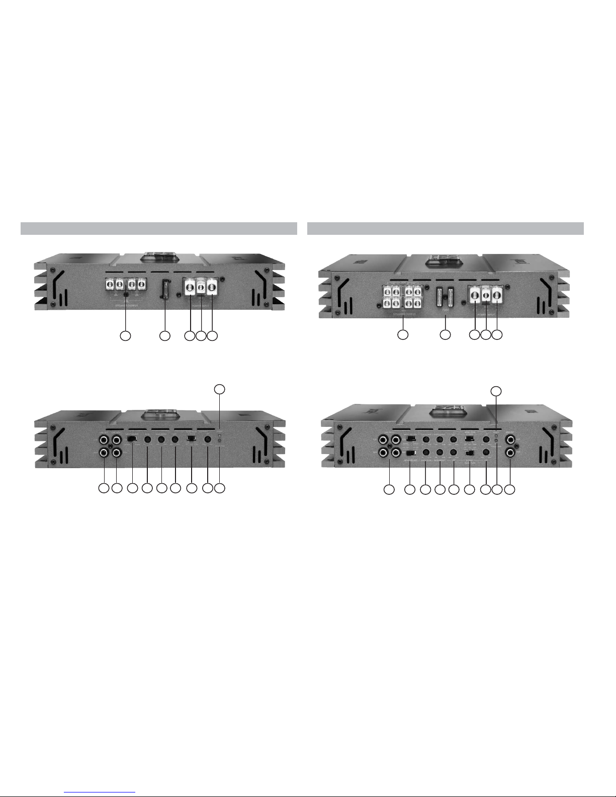
13 Power LED
Shows the operation mode of the amplifier.
14 Protection LED
The red LED indicates malfunctions of the amplifier.
The DARK BLUE amplifiers have several electronic protection cir-
cuits that shut off the amplifier at overheating, overloading, short-
circuit on loudspeaker, low-ohmic mode or defective power supply.
Please check for connecting failures such as short-circuits, wrong
connections and over-temperature.
If the amplifier does not turn on it is defect and has to be send to
your local authorized dealer for repair service. A detailed descrip-
tion of the malfunction and the purchase receipt has to be atta-
ched.
15 Signal outputs
Full range RCA outputs to connect other amplifiers.
TECHNICAL DATA DARK BLUE TWO
TECHNICAL DATA DARK BLUE FOUR
Cont. power rating at 4 Ohms per channel . . . . . . . . . . . . . . . . . . . . . . 2 x 80/160 Watts RMS/Music
Cont. power rating at 2 Ohms per channel . . . . . . . . . . . . . . . . . . . . . . 2 x 120/240 Watts RMS/Music
Cont. power rating at 1 ch. bridged at 4 Ohms . . . . . . . . . . . . . . . . . . . 1 x 200/400 Watts RMS/Music
Frequency response . . . . . . . . . . . . . . . . . . . . . . . . . . . . . . . . . . . . . . . . . . . . . . . . . 10 Hz - 30 kHz
Bassboost . . . . . . . . . . . . . . . . . . . . . . . . . . . . . . . . . . . . . . . . . . . . . . . . . . . . . . . . . . . . . 0 - 18 dB
Setting range highpass . . . . . . . . . . . . . . . . . . . . . . . . . . . . . . . . . . . . . . . . . . . . . . . 15 Hz - 4 kHz
Setting range lowpass . . . . . . . . . . . . . . . . . . . . . . . . . . . . . . . . . . . . . . . . . . . . . . . . 40 Hz - 4 kHz
Setting range bandpass . . . . . . . . . . . . . . . . . . . . . . . . . . . . . . . . . . . . . . . . . . . . . . . 15 Hz - 4 kHz
Total harmonic distortion (THD) . . . . . . . . . . . . . . . . . . . . . . . . . . . . . . . . . . . . . . . . . . . . . < 0,03%
TIM distortion . . . . . . . . . . . . . . . . . . . . . . . . . . . . . . . . . . . . . . . . . . . . . . . . . . . . . . . . . . < 0,04%
Signal to noise ratio . . . . . . . . . . . . . . . . . . . . . . . . . . . . . . . . . . . . . . . . . . . . . . . . . . . . . . > 93 dB
Input impedance . . . . . . . . . . . . . . . . . . . . . . . . . . . . . . . . . . . . . . . . . . . . . . . . . . . . . . . 10 kOhms
Input sensitivity . . . . . . . . . . . . . . . . . . . . . . . . . . . . . . . . . . . . . . . . . . . . . . . . . . . . . .200 mV - 8 V
Fuse . . . . . . . . . . . . . . . . . . . . . . . . . . . . . . . . . . . . . . . . . . . . . . . . . . . . . . . . . . . . .1 x 30 Ampere
Dimensions (H x W x D) in mm . . . . . . . . . . . . . . . . . . . . . . . . . . . . . . . . . . . . . . . . . 53 x 283 x 277
Weight net. . . . . . . . . . . . . . . . . . . . . . . . . . . . . . . . . . . . . . . . . . . . . . . . . . . . . . . . . . . . . . . 4,0 kg
Cont. power rating at 4 Ohms per channel . . . . . . . . . . . . . . . . . . . . . . . 4 x 60/120 Watts RMS/Music
Cont. power rating at 2 Ohms per channel . . . . . . . . . . . . . . . . . . . . . . . 4 x 90/180 Watts RMS/Music
Cont. power rating at bridged at 4 Ohms . . . . . . . . . . . . . . . . . . . . . . . 2 x 180/360 Watts RMS/Music
Frequency response . . . . . . . . . . . . . . . . . . . . . . . . . . . . . . . . . . . . . . . . . . . . . . . . . 10 Hz - 30 kHz
Bassboost . . . . . . . . . . . . . . . . . . . . . . . . . . . . . . . . . . . . . . . . . . . . . . . . . . . . . . . . . . . . .0 - 18 dB
Setting range highpass . . . . . . . . . . . . . . . . . . . . . . . . . . . . . . . . . . . . . . . . . . . . . . . 15 Hz - 4 kHz
Setting range lowpass . . . . . . . . . . . . . . . . . . . . . . . . . . . . . . . . . . . . . . . . . . . . . . . . 40 Hz - 4 kHz
Setting range bandpass . . . . . . . . . . . . . . . . . . . . . . . . . . . . . . . . . . . . . . . . . . . . . . . 15 Hz - 4 kHz
Total harmonic distortion (THD) . . . . . . . . . . . . . . . . . . . . . . . . . . . . . . . . . . . . . . . . . . . . . < 0,03%
TIM distortion . . . . . . . . . . . . . . . . . . . . . . . . . . . . . . . . . . . . . . . . . . . . . . . . . . . . . . . . . . < 0,04%
Signal to noise ratio . . . . . . . . . . . . . . . . . . . . . . . . . . . . . . . . . . . . . . . . . . . . . . . . . . . . . . > 93 dB
Input impedance . . . . . . . . . . . . . . . . . . . . . . . . . . . . . . . . . . . . . . . . . . . . . . . . . . . . . . . 10 kOhms
Input sensitivity . . . . . . . . . . . . . . . . . . . . . . . . . . . . . . . . . . . . . . . . . . . . . . . . . . . . . .200 mV - 8 V
Fuse . . . . . . . . . . . . . . . . . . . . . . . . . . . . . . . . . . . . . . . . . . . . . . . . . . . . . . . . . . . . . . .2 x Ampere
Dimensions (H x W x D) in mm . . . . . . . . . . . . . . . . . . . . . . . . . . . . . . . . . . . . . . . . . 53 x 362 x 277
Weight net. . . . . . . . . . . . . . . . . . . . . . . . . . . . . . . . . . . . . . . . . . . . . . . . . . . . . . . . . . . . . . . 5,0 kg
Due to the high quality standard Helix products achieved an excel-
lent international reputation. Therefore we grant a warranty peri-
od of 2 years.
The products checked and tested carefully during the entire pro-
duction process. In the case of service note the following:
1) The 2 years warranty period commences with the purchase of
the product and is applicable only to the original owner.
2) During the warranty period we will rectify any defects
due to faulty material or workmanship by replacing or repai
ring the defective part at our decission.
Further claims, and in particular those for price reduction,
cancellation of sale, compensation for damages or subse
quential damages, are excluded. The warranty period is not
altered by the fact that we have carried out warranty work.
3) Unauthorized tampering with the product will invalidate this
warranty.
4) Consult your authorized dealer first, if warranty service is nee-
ded. Should it be necessary to return the product to the fac-
tory, please insure that
a) the product is packed in original factory packing in
good condition
b) the warranty card has been filled out and attached to the
product
c) the product is shipped prepaid, i.e. at your expense
and risk
d) the receipt/invoice as proof of purchase is enclosed
5) Excluded from the warranty are:
a) Shipping damages, either readily apparent or concea-
led (claims for such damages must be immediately
notified to the forwarding agent).
b) Scratches in metal parts, front panels or covers etc.
This must be notified to your dealer within 5 days of purchase.
c) Defects caused by incorrect installation or connec-
tion, by operation errors, by overloading or by external force.
d) Products which have been repaired incorrectly or
modified or where the product has been opened by
other persons than us.
e) Consoquential damages to other equipments.
f) Reimbursement when repairing damages by third
parties without our previous permission.
WARRANTY REGULATION
Gewerbegebiet Lake II · Hünegräben 26 · D-57392 Schmallenberg
Tel.: ++49 (0) 29 72-97 88 0 · Fax: ++49 (0) 29 72-97 88 88
E-mail: helix@audiotec-fischer.com · Internet: www.audiotec-fischer.com