HELIX P 200 User manual

2-Channel High End Amplifier
GERMANY
BEDIENUNGSANLEITUNG
INSTRUCTION MANUAL
deutsch/english

5
Dear Customer,
congratulations on your purchase of this high-quality HELIX
PRECISION amplifier. This series highlights best quality,
excellent manufacturing and state-of-the-art technology.
After 27 years of experiences in the research & develop-
ment of audio products this amplifier generation sets new
standards. The attractive typical HELIX PRECISION design
makes this amplifier an outstanding and top of the class
product.
We wish you many hours of enjoyment with your new
HELIX amplifier.
Yours
AUDIOTEC FISCHER Team
General installation instructions for HELIX amplifiers
To find out how HELIX amplifiers work best for you, read this
manual carefully and follow the instructions for installation. We
guarantee that this product has been checked for proper functio-
ning before shipping.
Before you start installation, disconnect the car battery at the
minus pole. We would urge you to have the installation work car-
ried out by a specialist as verification of correct installation and
connection of the unit is a prerequisite for warranty cover of the
HELIX amplifier.
Install your amplifier at a dry location where there is sufficient air
circulation to ensure adequate cooling of the equipment. For
safety reasons, the amplifier must be secured in a professional
manner. This is performed by means of four fixing screws scr-
ewed into a mounting surface offering sufficient retention and sta-
bility.
Before drilling the holes for the screws, carefully examine the area
around the installation position and make sure that there are no
electrical cables or components, hydraulic brake lines or any part
of the petrol tank located behind the mounting surface - otherwi-
se these could be damaged. You should be aware of the fact that
such components may also be concealed in the double-skin trim
panels/mouldings.
General instruction for connecting the amplifiers
The HELIX amplifiers may only be installed in motor vehicles
which have a 12-volt minus pole connected to the chassis ground.
Any other system could cause damage to the amplifier and the
electrical system of the vehicle.
The plus cable from the battery for the complete system should be
provided with a main fuse at a distance of max.
30 cm from the battery. The value of the fuse is calculated from the
maximum total current input of the car audio system.
Install the cabling in a manner which precludes any danger of the
leads being exposed to shear, crushing or rupture forces. If there are
sharp edges in the vicinity (e.g. holes in the bodywork) all cables
must be cushioned and protected to prevent fraying.
Never lay the power supply cables adjacent to leads and lines
connecting other vehicle equipment (fan motors, fire detection
modules, gas lines etc.).
In order to ensure safe installation, use only high-quality connections
and materials. Ask your dealer for high quality accessories.
ENGLISH
Due to the high quality standard Helix products achieved an excel-
lent international reputation. Therefore we grant a warranty peri-
od of 2 years.
The products checked and tested carefully during the entire pro-
duction process. In the case of service note the following:
1) The 2 years warranty period commences with the purchase of
the product and is applicable only to the original owner.
2) During the warranty period we will rectify any defects
due to faulty material or workmanship by replacing or repai
ring the defective part at our decission.
Further claims, and in particular those for price reduction,
cancellation of sale, compensation for damages or subse
quential damages, are excluded. The warranty period is not
altered by the fact that we have carried out warranty work.
3) Unauthorized tampering with the product will invalidate this
warranty.
4) Consult your authorized dealer first, if warranty service is nee-
ded. Should it be necessary to return the product to the fac-
tory, please insure that
a) the product is packed in original factory packing in
good condition
b) the warranty card has been filled out and attached to the
product
c) the product is shipped prepaid, i.e. at your expense
and risk
d) the receipt/invoice as proof of purchase is enclosed
5) Excluded from the warranty are:
a) Shipping damages, either readily apparent or concea-
led (claims for such damages must be immediately
notified to the forwarding agent).
b) Scratches in metal parts, front panels or covers etc.
This must be notified to your dealer within 5 days of purchase.
c) Defects caused by incorrect installation or connec-
tion, by operation errors, by overloading or by external force.
d) Products which have been repaired incorrectly or
modified or where the product has been opened by
other persons than us.
e) Consoquential damages to other equipments.
f) Reimbursement when repairing damages by third
parties without our previous permission.
WARRANTY REGULATION

6
Connecting the remote lead
Connecting the battery cable
Connecting the ground cable
Fuses 3 x 25 Ampere
Fuse function indication
Signal inputs
Level controls for input sensitivity
Selector switch for channels A and B
Mono/Bridged/Stereo selector
Speaker terminals for CH A
Speaker terminals for CH B
Frequency control highpass A and B
Frequency control lowpass A and B
Control to raise the center frequency
Adjustment of the center frequencies
Colour protection system
1
2
3
4
5
6-7
8-9
10
11
12
13
14
15
16
17
18-20
EQUIPMENT FEATURES AND CONTROL ELEMENTS PRECISION P200
1 Connecting the remote lead
The remote lead is connected to the automatic antenna (aerial
positive) output of the head unit (radio). This is only activated if
the head unit is switched ON. Thus the amplifier is switched on
and off with the head unit.
2 Connecting the battery cable
Connect the +12 V power cable to the positive terminal of the
battery. Recommended cross section: min. 16mm2.
3 Connecting the ground cable
The ground cable should be connected to a central ground refe-
rence point (this is located where the negative terminal of the bat-
tery is grounded at the metal body of the vehicle), or to a bright
bare-metal location on the vehicle chassis, i.e. an area which has
been cleaned of all paint residues.
4 Fuses
The input fuses are connected in parallel and provide protection
against an internal equipment fault, i.e. the system must be addi-
tionally protected by a further line fuse located in the vicinity of
the battery (max. distance from battery: 30 cm). The fuse rating
is 3 x 25 ampere for both amplifiers.
5 Fuse function indication
If the fuses (4) are destroyed due to malfunction the red LED illu-
minates. In normal operation the LED turns off.
6 - 7 Signal inputs
The PRECISION amplifiers have RCA connectors for RCA cables
that can be connected with the pre-amplifier output of the line-
outputs of the headunit or with a pre-amplifier. This connectors
are gold-plated to ensure a better signal transmission.
8-9 Level controls for input sensitivity
These controls can be used to match the input sensitivity of the
individual channels to the output voltage of the connected head
unit. These controls are not volume controls and are solely inten-
ded for the purpose of sensitivity trimming. The control range
extends from 300 mV to 8,5 V.
10 Selector switch for channels A and B
To switch the internal active crossover to highpass/full range (line-
ar) or lowpass.
If this switch is set on Highpass the exactly frequency can be set
with control No. 21.
At switch position Lowpass/Bandpass the highpass is always
active. That means a Bandpass is built in any case. With control
21 adjust the highpass and with control 22 adjust the lowpass.
Thus every desired Bandpass between 15 Hz and 4000 Hz can be
adjusted.
Caution! To avoid a lost of sound pressure make sure that
the crossover frequencies of high- and lopass are separa-
ted of 2 octaves when building a Bandpass.
That means: If the lowpass signal is adjusted to 320 Hz the hig-
hpass should be adjusted 2 octaves lower on approx. 80 Hz (1
octave=double frequency or half frequency).
If a subwoofer is connected we recommend to use high-
pass control 21 as variable subsonic filter or to turn con-
trol 21 counter-clockwise to 15 Hz to get a subsonic filter.
11 Mono/Bridged/Stereo selector
To set the operating mode of the amplifier.
Stereo: If the amplifier operates in 2-channel mode the switch
has to be set on stereo position and both inputs (6 and 7) must
be used.
Bridged: If the amplifier operates in Mono mode the switch has
to be set on Bridged position. In this case both channels works as
one (Mono) channel. On the position “Bridged” both inputs A and
B (6 and 7) must be used.
Mono: As on position “Bridged” the amplifier operates in Mono
mode were both channels works as one (Mono) channel. On the
position “Mono” only the input A (6) must be used. This is neces-
sary if only Mono signal is available.
Warning:
The impedance of the woofer in bridged mode must not be lower
than 4 Ohms!
12 Speaker terminals for channels A
To connect the speaker cables.
13 Speaker terminals for channels B
To connect the speaker cables.
7
6
8
9
3
2
154
18
19
20
10
11
14
15
16
17
12
13

7
Never connect the loudspeaker cables with the car chas-
sis gound. It damages your amplifier. All speaker systems
must be connected in-phase, this means plus to plus and minus
to minus. The plus pole is normally marked on the speaker. In
addition, the amplifier can operate channels A and B as well as C
and D in stereo or mono mode. The amp also can be connected
for tri-mode use with one pair of wires (AB or CD) and have a
third speaker connected in mono mode.
14 Frequency level control for highpass of CH A and B
Control for the adjustment of the crossover frequency from 15Hz
to 4 kHz.
15 Frequency level control for lowpass of CH A and B
Control for the adjustment of the crossover frequency from 15Hz
to 4 kHz.
16 Control to raise the center frequency
This control enables the center frequency set at control 27 to be
raised from 0 to 9 dB if the switch 19 is on HP or LP position.
17 Adjustment of center frequencies
Control 17 can be used to select the frequency from 40 - 120 Hz
of the adjusted lowpass. This can be enhanced with control 16
from 0 to 9 dB.
It is useful to emphasize or correct a determined frequency of the
subwoofer (kickbass).
18-20 CPS - colour protection system
The LEDs show the operation status of the amp. Green=O.K.;
Yellow=the speakers wires are shorted to ground; Red=overhea-
ted. If the amp shuts off due to overheating it will take some time
(depending on the outside temperature) until it switches on
again.
TECHNICAL DATA PRECISION P200
Cont. power rating at 4 Ohms per channel . . . . . . . . . . . . . . . . . . . . . 2 x 130/220 Watts RMS/Music
Cont. power rating at 2 Ohms per channel . . . . . . . . . . . . . . . . . . . . . . 2 x 225/380 Watts RMS/Music
Cont. power rating at 1 Ohm per channel . . . . . . . . . . . . . . . . . . . . . . 1 x 340/580 Watts RMS/Music
Cont. power rating at bridged at 4 Ohms . . . . . . . . . . . . . . . . . . . . . . . 1 x 450/765 Watts RMS/Music
Cont. power rating at bridged at 2 Ohms . . . . . . . . . . . . . . . . . . . . . . 1 x 675/1145 Watts RMS/Music
Frequency response . . . . . . . . . . . . . . . . . . . . . . . . . . . . . . . . . . . . . . . . . . . . . . . . . 15 Hz - 20 kHz
Bassboost . . . . . . . . . . . . . . . . . . . . . . . . . . . . . . . . . . . . . . . . . . . . . . . . . . . . . . . . . . . . . .0 - 9 dB
Bassboost center frequency range . . . . . . . . . . . . . . . . . . . . . . . . . . . . . . . . . . . . . . . . . .40 - 120 Hz
Setting range highpass . . . . . . . . . . . . . . . . . . . . . . . . . . . . . . . . . . . . . . . . . . . . . . . 15 Hz - 4 kHz
Setting range lowpass . . . . . . . . . . . . . . . . . . . . . . . . . . . . . . . . . . . . . . . . . . . . . . . . 15 Hz - 4 kHz
Total harmonic distortion (THD) . . . . . . . . . . . . . . . . . . . . . . . . . . . . . . . . . . . . . . . . . . . . < 0,006%
TIM . . . . . . . . . . . . . . . . . . . . . . . . . . . . . . . . . . . . . . . . . . . . . . . . . . . . . . . . . . . . . . . . . < 0,01%
Signal to noise ratio . . . . . . . . . . . . . . . . . . . . . . . . . . . . . . . . . . . . . . . . . . . . . . . . . . . . . . > 95 dB
Damping factor . . . . . . . . . . . . . . . . . . . . . . . . . . . . . . . . . . . . . . . . . . . . . . . . . . . . . . . . . . . > 600
Input impedance . . . . . . . . . . . . . . . . . . . . . . . . . . . . . . . . . . . . . . . . . . . . . . . . . . . . . . . 10 kOhms
Input sensitivity . . . . . . . . . . . . . . . . . . . . . . . . . . . . . . . . . . . . . . . . . . . . . . . . . . . . .300 mV - 8,5 V
Fuse . . . . . . . . . . . . . . . . . . . . . . . . . . . . . . . . . . . . . . . . . . . . . . . . . . . . . . . . . . . . .3 x 25 Ampere
Dimensions (H x W x D) in mm . . . . . . . . . . . . . . . . . . . . . . . . . . . . . . . . . . . . . . . . . 35 x 432 x 240
Weight net. . . . . . . . . . . . . . . . . . . . . . . . . . . . . . . . . . . . . . . . . . . . . . . . . . . . . . . . . . . . . . 4,7 kgs
www.audiotec-fischer.com
Other HELIX Amplifier manuals
HELIX
HELIX V EIGHT DSP MK2 User manual
HELIX
HELIX E400 Esprit User manual
HELIX
HELIX HXA 20 User manual
HELIX
HELIX DARK BLUE User manual
HELIX
HELIX V EIGHT DSP User manual

HELIX
HELIX V EIGHT DSP User manual
HELIX
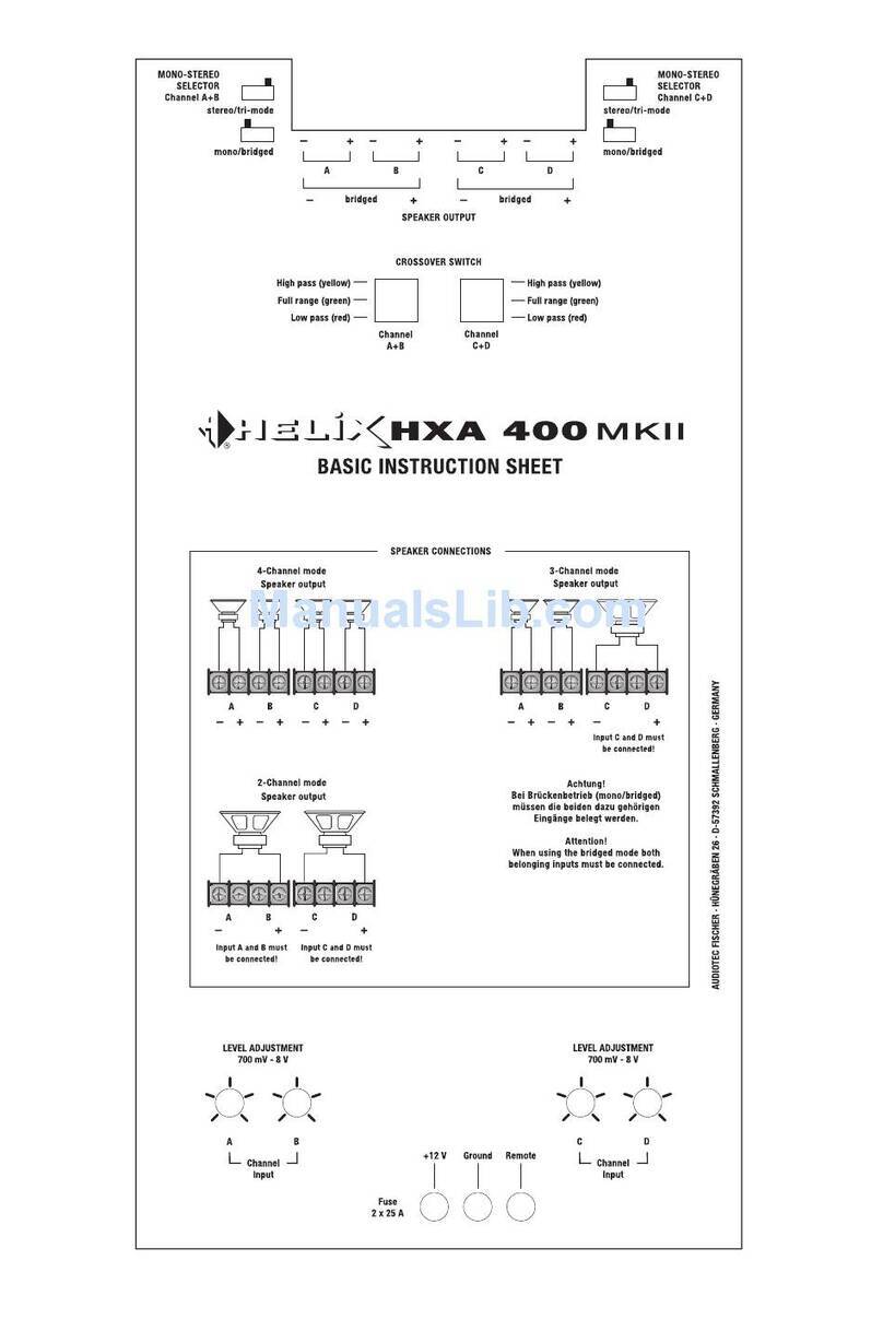
HELIX HXA 400 MKII - BASIC User manual
HELIX
HELIX PP20 DSP User manual
HELIX
HELIX A4 Competition User manual
HELIX
HELIX M FOUR DSP User manual

HELIX
HELIX I58X User manual
HELIX
HELIX Blue B ONE User manual
HELIX
HELIX B Five User manual
HELIX
HELIX H 500 ESPRIT User manual
HELIX
HELIX Competition SPXL 1000 User manual
HELIX
HELIX B Five User manual
HELIX
HELIX G TWO User manual
HELIX
HELIX P SIX DSP MK2 User manual
HELIX
HELIX D FOUR User manual
HELIX
HELIX G ONE User manual
