HELIX I58X User manual


PAGE 2 OPERATION MANUAL V2.0
Please read and follow the instructions in this manual thoroughlyto obtain optimum results from this unit. We also
recommend that you keep this manual handyforfuture reference.
Safety Precautions
• Be sure to read the instructions in this section carefully before use.
• Make sure to observe the instructions in this manual as the conventions of safety symbols and messages regarded as
very important precautions are included.
Safety symbols and messages described below are used in this manual to prevent bodily injury and property damage
which could result from mishandling. Before operating your product, read this manual rst and understand the safety
symbols and messages so you are thoroughly aware of the potential safety hazards.
WARNING Indicates a potentially hazardous situation which, if mishandled, could result
in death or serious injury.
Indicates a potentially hazardous situation which, if mishandled, could result
in moderate or minor personal injury, and/or property damage.
CAUTION
Make sure to observe the following handling precautions so that a re or personal injury does not result from leakage or
explosion of the battery.
• Do not short, disassemble, heat or put the battery into a re.
• Never charge batteries of the type which are not rechargeable.
• Do not solder a battery directly.
• Be sure to use the specied type of battery.
• Note the correct polarity when inserting a battery in the unit.
• Avoid locations exposed to the direct sunlight, high temperature and high humidity when storing batteries.
WARNING To prevent the electromagnetic wave from badly inuencing medical
equipment, make sure to switch o the units power when placing it in close
proximity to the medical equipment.
Battery discharges naturally according to a certain pattern even when not in
use. For best performance and a prolonged lifespan, battery should be charged
regularly aer every use or every month when the system is in storage and not
being used. CD player optical pickup head is a very delicate device and sensitive
to humidity. Please avoid using it in high humidity areas to avoid damage.
CAUTION

OPERATION MANUAL V2.0 PAGE 3
Congratulations and thank you for purchasing this multi-functional wireless portable amplier. To ensure a trouble-free
operation, please read the manual thoroughlyto fully understand its controls and functions.
The rear panel of this portable amplier is divided into 3 sections:
1. Module compartment
2. Control Unit compartment
3. Battery compartment
The Module Compartment is user congurable and user can access
the battery compartment to replace battery.
Helix 158X amplier 0~4 transmitters
(handheld/beltpack)
Switching power supply
(plugvaries from country to country)
Operation manual
ACCESSORIES
HX-8 ST Standard Tripod Stand
HX-8 DC Weatherproof Dust Cover
DM7SX Wired Microphone
Note: The above specications are subject to change without prior notice.
In the Box
MODULES & TRANSMITTERS
RX8TD True Diversity Receiver Module
RX8D Diversity Receiver Module
RP5 Repeater Module
DPR5 MP3 Recorder Module
HH6100 Handheld Transmitter
BP6100 Beltpack Transmitter
Optional Accessories
SPEAKER
HX-158x SP Passive Extension Speaker
HX-8 PSR Powered Extension Speaker

PAGE 4 OPERATION MANUAL V2.0
Parts and Functions
Charging the Battery
This amplier uses either two lead-acid batteries or one lithium battery. The battery power is levelled from 40%, 60%,
80% and FULL. If the LED stays at 40%, the battery might not be sustainable for long operation.
Battery Indicator Charging Indicator
CHARGING INDICATOR
LED Flashing RED Currently Recharging
LED Illuminated GREEN Fully Charged
LED Illuminated YELLOW Error / No Battery Detected
MIC/LINE 1
Volume Control
MIC/LINE 2
Volume Control
REVERB
Control
REVERB
On/O Button
VOICE PRIORITY
On/O Button
TREBLE/
BASS
MASTER
Volume Control
MIC/LINE 1
Level Switch
MIC/LINE 2
Level Switch
MIC/LINE INPUT 1
(Combo)
MIC/LINE INPUT 2
(Combo)
LINE IN Socket
(3.5mm)
LINE IN
Volume Control
LINE OUT
(6.3mm)
MASTER
Limiter Indicator
BLUETOOTH
Pairing Indicator
BLUETOOTH
On/O Button
Battery
Indicator
Charging
Indicator
Power
Switch
EXTERNAL SPEAKER
Socket (4-8Ω)
EXTERNAL SPEAKER
Volume Control
DC OUT
DC Output Jack (12V)
DC IN
DC Input Jack (30-32V/4A)
For Receiver /
MP3 Module

OPERATION MANUAL V2.0 PAGE 5
Charging Indicator
Module Compartment
For Receiver /
MP3 Module
For Receiver / Repeater /
MP3 Module
Sound control, eg. volume
and equaliser, of audio
output from HX-158x-II
is controlled only bythis
external amplier.

PAGE 6 OPERATION MANUAL V2.0
Using a Wired Microphone – INPUT 1 & INPUT 2
1. Plug a wired microphone with a 6.3mm or XLR connector to INPUT 1 or INPUT 2.
2. Slide MIC/LINE switch to MIC level.
3. Turn on master POWER and then adjust INPUT 1 or INPUT 2 volume control to desired level.
4. EQUALISER Treble/Bass (referto Page 10) and REVERB (refer to Page 11) levels can be adjusted individually.
TONE control REVERB eect

OPERATION MANUAL V2.0 PAGE 7
Using an Electronic Instrument – INPUT1 & INPUT 2
1. Plug an electronic guitar or keyboard with a 6.3mm plug or XLR connector to INPUT 1 or INPUT 2.
2. Slide MIC/LINE switch to MIC level.
3. Turn on master POWER and then adjust LINE volume control to desired level.
4. EQUALISER Treble/Bass (referto Page 10) and REVERB (refer to Page 11) levels can be adjusted individually.
TONE control REVERB eect

PAGE 8 OPERATION MANUAL V2.0
Music Audio Input – Smart Phone / Tablet / MP3 Player
1. Connect your device to the LINE IN 3.5mm jack using a 3.5mm 3-pole stereo audio cable.
2. Turn on master POWER and then adjust LINE IN volume control to desired level.
3. EQUALISER Treble/Bass levels can be adjusted individually (refer to Page 10).
TONE control

OPERATION MANUAL V2.0 PAGE 9
Operating BLUETOOTH Receiver
1. Turn on master POWER and then press the SWITCH button for 3 seconds to turn on the BLUETOOTH receiver.
You will hear “POWER ON” and the pairing indicator LED will ash green.
Approximately 9 seconds later you will hear “READY TO PAIR” and the pairing indicator LED will ash green and red.
2. Activate BLUETOOTH on your device (phone, tablet, PC., etc) and pair with external device named “BT AUDIO”.
Aer successful pairing, you will hear “PAIR COMPLETED, DEVICE CONNECTED”, and the pairing indicator LED will
illuminate green.You can now play music through your HX-158x-II PA.
3. Adjust mastervolume control to a desired level.
4. EQUALISER Treble/Bass levels can be adjusted individually (refer to Page 10).
POWER ON
READYTO PAIR
Flash
GREEN
Flash
GREEN
Solid
GREEN
Flash
RED
PAIR COMPLETED
DEVICE CONNECTED
TONE control

PAGE 10 OPERATION MANUAL V2.0
Important
• BLUETOOTH automatically turns o aer 5 minutes if no music is playing.
• Press the SWITCH button for disconnection or to prepare for a new pairing.
• BLUETOOTH memorises and automatically connects to last-paired device.
EQUALISER forWIRED / WIRELESS MICROPHONE and MUSIC
EQUALISER adjustment is actually used to increase or reduce the high/medium/low frequency component of the
speaker’s restored sound. It is so-called raising or attenuating TREBLE/BASS via frequency-specic volume knobs to
improve human voices or make musical instruments’ sound more prominent. According to the scale marks on the panel,
clockwise adjustment is to increase and boost and opposite direction to decrease and attenuate.
Adjust the level of high frequency (TREBLE) and low frequency (BASS) respectively. All signals have been balanced by the
high and low sounds aer entering the amplier so it is not necessary to adjust the EQUALISER during the output to the
speaker. It is recommended to maintain the position of BASS and TREBLE at 12 o’clock.
KNOBS BASS TREBLE
FUNCTION Reduce / Increase
the low frequency component
of the sound
Reduce / Increase
the high frequency component
of the sound
RANGE -12dB ~ +12dB
DEFAULT 12 o’cock
Adjustment Reference:
BASS: It is the basic part of the sound. It accounts for 70% of the entire audio energy and is an
important component to display the music style. When appropriate, the BASS is relaxed and the sound
is full and so. If you feel the sound is thin, you can moderately increase the BASS. If you feel the sound
is mued, not clear, or too nasal, you can moderately reduce the BASS.
TREBLE: It’s the frequency that aects the sound layering. If you feel that the sounds of instruments
such as Piccolo and Flute are too prominent, orthe tooth sound of the voice is too heavy and the tone
is sharp, you can moderately reduce the TREBLE.

OPERATION MANUAL V2.0 PAGE 11
Operating Voice Priority
Voice Priority operation is only necessary when CD/USB/MP3 is playing.
When the Voice Priority switch is ON, the ducking function will be activated. While the music is playing,
voice input from either a Wired or Wireless Microphone will temporarily override and lower the volume
of the background music and speech will be heard more clearly.
Background music will return to its original volume when no audio is detected from the microphone for a few seconds.
Please Note: If the microphone is used within close proximity ofthe HX-158x-II speaker or other high level music
playback the Voice Priority feature may be activated and lower the music level. It is recommended that if the microphone
is not required whilst music is being played to switch o or mute the microphone.
Reverb
This function can add extra depth to the sound of WIRED or WIRELESS MICROPHONE to create
a realistic acoustic ambience. You can adjust the reverb depth by using the REVERB knob. The depth range
is from MIN through MAX. The MIN level produces no eect, while MAX level produces maximum reverb
depth. When REVERB is turned o, no eect is applied.
Limiter Function
There’s an interior anti-overload circuit to protect the amplier from being damaged due to over volume output, this
feature will automatically lower the output when it goes overthe limit.
The purpose of the six input signal source (microphone, musical instrument or music) signal level indicators, from -20dB
(min) to +6dB (max), is to display the real-time dynamic level of the sound signal. Please do not exceed the 5th indicator
(+3dB) ashing when adjusting the volume of each input to prevent distortion.

PAGE 12 OPERATION MANUAL V2.0
Using a Wireless Transmitter
Parts and Functions
RF Signal Meter
1. Press the SYNC button on the
transmitter.
Channel Synchronising ofthe Receiverand Transmitter
Align infrared areas of the receiver and transmitter within 10~30cm.
2. The transmitter’s LED will illuminate
to denote synchronisation signal
transmitted.
3. The channel number on the receiver
LCD will match the transmitter,
which means the receiver has been
successfully synchronised.
1. Press the SYNC button on the
receiver.
Sync Channel from Transmitter ÚReceiver
Sync Channel from Receiver ÚTransmitter
2. The transmitter’s LED will illuminate
to denote synchronisation signal
recieved.
3. The channel number on the
transmitter LCD will match the
receiver, which means the transmitter
has been successfully synchronised.
Channel
DiversityA/B
Antenna
Transmitter Battery
Power
Audio Signal
Meter
IR Sensor
Power /
Volume Control
IrDA Synchronisation
Button
LCD
Frequency DOWN Button UP Button SET Button

OPERATION MANUAL V2.0 PAGE 13
Channel Scanning
For interference-free operation, a cleaner channel might be necessary ifthe current one receives too much interference.
To operate scanning:
Adjusting Squelch (SQ) Level
When interference is encountered try reducing the sensitivity of the receiver, thus making it less susceptible to
interference. To operate squelch setting:
Since increasing the squelch level will also reduce the reception distance, it’s recommended to choose the lowest level
that can eliminate the interference.
If this still does not solve the problem it means this frequency is not suitable. Adjust the squelch backto its default level
(LE-01) and use the scan function to locate a clear, interference-free channel.
1. Press (down) or (up) button until the frequency
icon [FREQ] appears at the bottom of the LCD.
2. Hold SET button until this icon [FREQ] ashes to denote
readiness for setting.
3. Press (down) or (up) button to nd and locate a clear,
interference- free channel.
4. Aer a channel is chosen, press SET button or wait 5 seconds
to store the setting.
1. Press (down) or (up) button to turn to the squelch
setting page.
2. Hold SET button until this icon [SQ] ashes to denote
readiness for setting.
3. Press (down) or (up) button to select a new squelch
level between 01 and 10. The default level is 01.
4. Aer a level is chosen, press SET button or wait 5 seconds to
store the setting.

PAGE 14 OPERATION MANUAL V2.0
Volume and Other Settings
1. Turn on master POWER and then adjust volume control to the desired level.
2. EQUALISER Treble/Bass (referto Page 10) and REVERB (refer to Page 11) levels can be adjusted individually.
TONE control REVERB eect

OPERATION MANUAL V2.0 PAGE 15
HELIX-158x-II HELIX-8 PSRHELIX-8 PSR
HELIX-8 PSR
HELIX-8 PSR
WirelessAudio Link – Repeat all audio to linked HX-158x-II and HX-8 PSR
HX-158x-II operates as the MASTER unit in a wireless audio link with other HX-158x-II or HX-8 PSR active companion
powered speakers. The RP5 repeater module of master HX-158x-II can transmit all audio signals, including wired/wireless
microphone, music, instrument, etc. to other units installed with receiver module.
RP5 Module
Parts and Functions
Changing Channels
Press LEFT button to increase the DOUBLE-digit
channel number.
Press RIGHT button to increase the SINGLE-digit
channel number.
Channel Selectors Channel Indicator Antenna Connector (TNCtype)
Output Power
Switch (on PCB).
Default at LOW.
Power Button Unit GAIN Control Audio Input (3.5mm) AUX IN GAIN Control

PAGE 16 OPERATION MANUAL V2.0
Music Audio Input – Smart Phone / Tablet / MP3 Player
1. Connect your device to the AUX IN 3.5mm jack using a 3.5mm 3-pole stereo audio cable.
2. Use a mini screw driverto adjust the volume ofthe input audio.
Adjusting the Internal Audio Gain Level
Use a mini screw driverto adjust the volume of audio sources in the master unit.
Output Power Setting
• LOW position (default) for low output power and HI for high output power.
• LOW output power will reduce the RF transmission distance and HI output
power will extend the possible RFtransmission distance.
• If the module is installed on battery-powered ampliers, remember HI output
power places slightly more load on the battery and will reduce operating
duration faster than LOW output power.

OPERATION MANUAL V2.0 PAGE 17
Transmitting from Master to Companion Units
1. Install an RP5 repeater module on the master HX-158x-II. Set the channel/frequency on the repeater module which
will be used to transmit signals to other units. The channel/frequency must be dierent from other modules on all
master and companion units.
2. Install a RX8TD/RX8D receiver module on companion HX-158x-II or HX-8 PSR. Set the channel/frequency on the
receiver module which will be used to receive signals from the master HX-158x-II. Both repeater and receiver module
must be the same channel/frequency.
3. Turn on master POWER of HX-158x-II and each HX-8 PSR and then adjust master VOLUME control to a desired
level. Turn on power of EACH HX-8 PSR and then adjust the volume control to a desired level.
4. EQUALISER Treble / Bass levels can be adjusted individually (refer to Page 10).
MASTER RP5
Repeater Module
COMPANION RX8TD/RX8D
Receiver Module
HX-158x-II HX-8 PSR
TONE control

PAGE 18 OPERATION MANUAL V2.0
Extra Coverage
To reach wider coverage, the companion unit HX-158x-II or HX-8 PSR can serve as SUB-MASTER to transmit signals to
SUB-COMPANION units.
Important: Please do not set the SUB-COMPANION as next MASTER in order to guarantee best sound quality.
For this purpose, please install a repeater module on the SUB-MASTER unit and a receiver module on SUB-COMPANION
units (same procedures as STEP 1 & 2). Both repeater and receiver module must be the same channel and same
frequency which must be dierent from former repeater and receiver module.
SUB-MASTER RP5
Repeater Module
RX8TD/RX8D
Receiver Module
RX8TD/RX8D
Receiver ModuleSUB-COMPANION
HX-158x-IIHX-8 PSR HX-8 PSR HX-8 PSR
HX-8 PSR
HX-8 PSR

OPERATION MANUAL V2.0 PAGE 19
Connecting a Passive Companion Speaker
1. Plug the passive companion speaker’s audio cable with a 6.3mm connector to the speaker input socket
of HX-158x SP or another 4~8Ω load speaker. Max cable length less than 20m.
2. Turn on master POWER and then adjust its individual volume control to a desired level.

PAGE 20 OPERATION MANUAL V2.0
Installing or Replacing a Receiver/Repeater/MP3 Module
There are four slots above the control panel and two on HX-MB module bracket for installing optional modules
which includes receiver, repeater and MP3 recorder modules.
1. Use a Phillips-head screwdriver (not included) to remove the screws of the blank cover panel or current
module’s panel.
2. To replace module, use a mini at-head screw driver (not included) to pry up the current module’s panel
and remove the module.
3. Gently insert the module into the slot by aligning its edges to the guide rails. Then push the panel to make sure
it’s been rmly connected.
4. Tighten up the screws.
Panel Slot
HX-MB Slot
Panel SlotPanel Slot
Table of contents
Other HELIX Amplifier manuals

HELIX
HELIX DARK BLUE User manual

HELIX
HELIX DARK BLUE FIVE User manual
HELIX
HELIX H 500 ESPRIT User manual
HELIX
HELIX P 200 User manual
HELIX
HELIX P ONE User manual
HELIX
HELIX G FOUR User manual
HELIX
HELIX Competition SPXL 1000 User manual

HELIX
HELIX HXA 40 User manual
HELIX
HELIX G TWO User manual

HELIX
HELIX DARK BLUE User manual
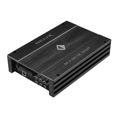
HELIX
HELIX M FOUR DSP User manual
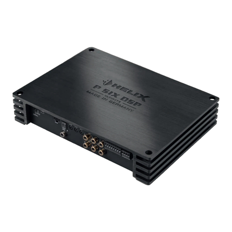
HELIX
HELIX ULTIMATE P SIX DSP User manual
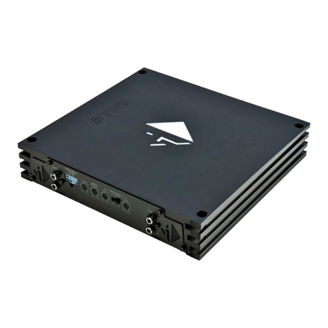
HELIX
HELIX blue B TWO User manual

HELIX
HELIX C ONE User manual
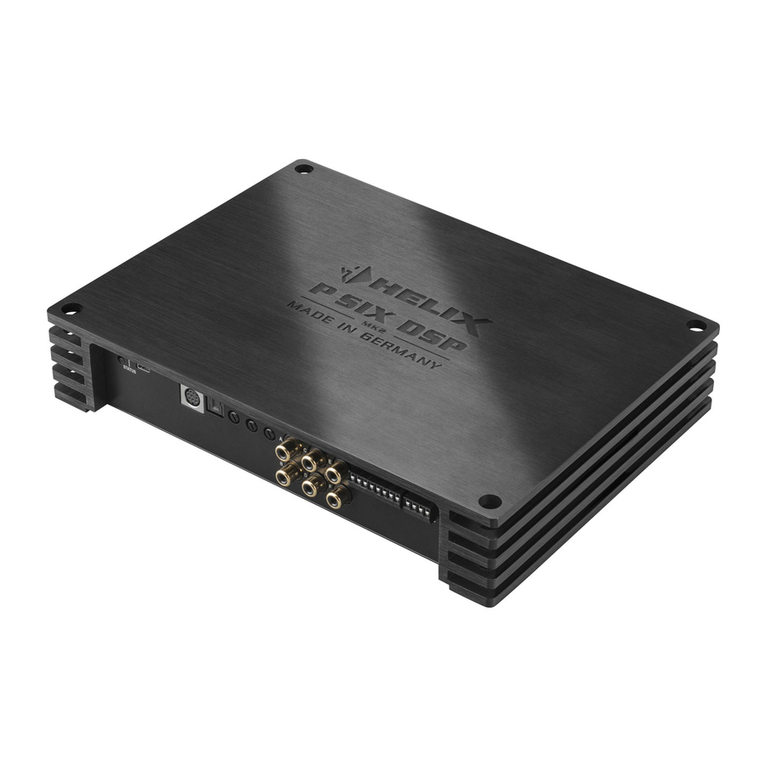
HELIX
HELIX P SIX DSP MK2 User manual
HELIX
HELIX B Five User manual
HELIX
HELIX G ONE User manual

HELIX
HELIX PP20 DSP User manual
HELIX
HELIX E400 Esprit User manual
HELIX
HELIX V TWELVE DSP MK2 User manual

