Jora Composters JK125 User manual

ASSEMBLY INSTRUCTIONS JK125
TOOLS REQUIRED: One knife to open packaging | Two ½” wrench or socket (metric 13) | One 9/16’ wrench or socket
(metric 14) | One #2 Philips (+) screwdriver NOTE: All bolts are 9/16” (metric 14) and nuts are ½” (metric 13)
We highly recommend 2 people work together to assemble. Also, we suggest placing
on soft surface when laying out and assembling: ie cardboard or a blanket.
Tools needed:
2 pc adjustable wrenches
1 pc Phillips Screwdriver
1 pc Flathead Screwdriver
All Measurements Are In Metric Units*

ASSEMBLY INSTRUCTIONS JK125
Tools needed:
2 pc adjustable wrenches
1 pc Phillips Screwdriver
1 pc Flathead Screwdriver
All Measurements Are In Metric Units*
Tools needed:
2 pc adjustable wrenches
1 pc Phillips Screwdriver
1 pc Flathead Screwdriver
All Measurements Are In Metric Units*
For all connections hand tighten only for step 1.
Place cross brace #4 on the ground
Set one piece of the stand #2 V shaped on top (note: the
stand has a front and back, back has 2 extra holes for
cross brace)
Insert threaded at each end rod #3 through bottom back
hole and cross brace and attach nut.
Insert bolt #6 and attach nut #7 through front lower hole
in stand to attach brace #4
Insert rod #3 through top middle hole and attach nut.
Slide hollow metal rods #1 over each of the threaded
rods previously completed
1
Slide long black tube #10 over top steel pipe.
Slide shortest black tube #12 over long black tube.
Slide octagon metal side #8(painted side down) over the
long black tube until it reaches the small black tube on
the bottom.
Slide on medium length black tube #11 until it reaches
metal side.
2

ASSEMBLY INSTRUCTIONS JK125
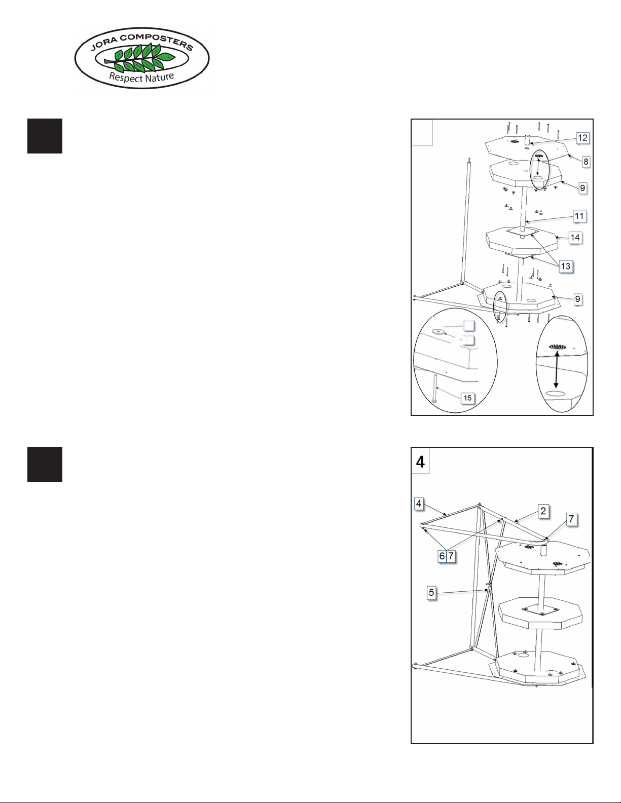
Slide the Octagonal foam insulation piece #9 (one of two with
ventilation holes) over the long and medium black tube until it
reaches the metal side piece. Line up ventilation holes.
Slide the square nylon piece #13 over the black tube until it
rests on the medium tube #11.
Slide on the octagonal insulator #14 (the one that does not
have ventilation holes)
Slide on 2nd square piece # 13 to rest on insulation and
sandwich the insulation.
Slide on 2nd medium plastic pipe #11
Slide on octagonal insulation piece #9 over the medium pipe.
Slide on 2nd metal side and line up ventilation holes.
Note: The diagram shows you can now insert the nylon bolts,
nuts and washers. I nd it easier to install these after Sketch
4 when the unit is standing up and after one panel has been
installed. It is up to you which you choose.
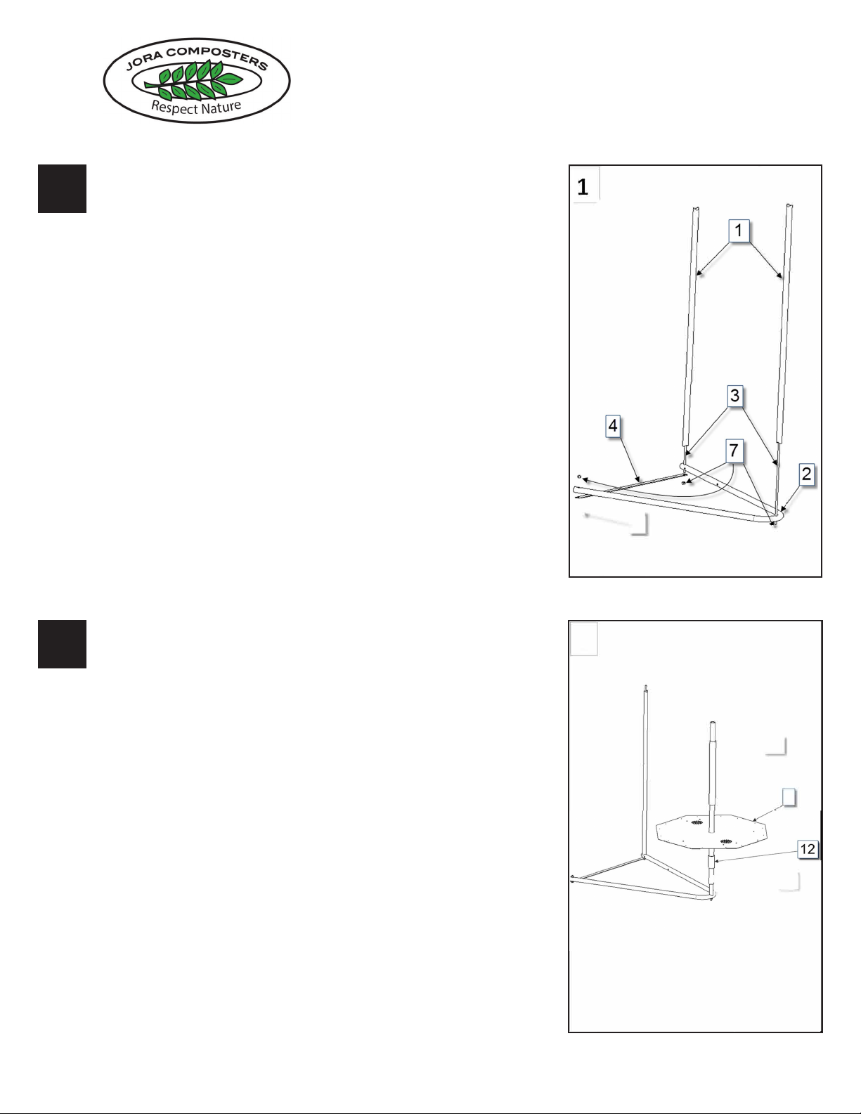
3
(Hand tighten only) Attach the cross brace #4 to the front hole
on the 2nd V shaped stand. Place 2nd side of the stand #2 on
the 2 metal threaded rods, and attach locknuts on the top and
bottom rods. Be sure the cross brace is on the threaded rod
and attached by the locknut.
Place and attach X brace #5 with bolts #6 and locknuts #7 to
rear of stand. Have 2 people stand up the composter. Tighten
all nuts and bolts.
Note: The ends of the hollow metal tubes are formed at
each end to conform to the sides to prevent spinning and
strengthens the composter. When tightening the locknuts you
may need the second person to lift the center slightly as well
as securing the nut to position this properly.
Line up the Octaganol insulation panels with the ventilation
holes and sides and insert plastic screws #15, through the
insulation, add washer#17 and bolt #16. (hand tighten) There
are no pre-drilled holes in the insulation, applying pressure to
the nut will force it through. Washers are only used on the end
panels. Repeat at other end.
For the middle section line up the sides and push the screws
through #15 and attach nut #16. (no washers are used for
these).
4
Tools needed:
2 pc adjustable wrenches
1 pc Phillips Screwdriver
1 pc Flathead Screwdriver
All Measurements Are In Metric Units*
Tools needed:
2 pc adjustable wrenches
1 pc Phillips Screwdriver
1 pc Flathead Screwdriver
All Measurements Are In Metric Units*

ASSEMBLY INSTRUCTIONS JK125
It is very important to have 2 people to add the side
panels to prevent the composter from spinning.
Line up the octagonal panels.
Place the side section with doors #20 on top with doors
pointing towards the front.
Line up the predrilled holes and insert the 4 screws #22
to attach panel and doors.
Add the second panel with locks #21 the same way
lining up the screw holes.
Adjust to locks screwing the latch in or out so it closes
comfortably and locks the 2 doors.
Note: Laying the tumbler back on the blanket for the
above after attaching the rst couple of panels may
make it easier to apply pressure to line up the holes.
5-6
6
7 8
\
\
I
Assembly
I
nstruction
JK
125
www.joracomposters.com
j
o
r
a
c
o
m
p
o
s
t
e
r
s
R
e
s
p
e
c
t
N
a
t
u
r
e
6
7 8
\
\
I
Assembly
I
nstruction
JK
125
www.joracomposters.com
j
o
r
a
c
o
m
p
o
s
t
e
r
s
R
e
s
p
e
c
t
N
a
t
u
r
e

ASSEMBLY INSTRUCTIONS JK125
Add the next panels the same way starting with #19 (with
a handle) then #18 (no handle) until all are attached .
Stand it up, check all screws, nuts, and bolts. When all
are secure you are ready to compost.
7-8
6
7
8
\
\
I
Assembly
I
nstruction
JK
125
www.joracomposters.com
j
o
r
a
c
o
m
p
o
s
t
e
r
s
R
e
s
p
e
c
t
N
a
t
u
r
e
6
7
8
\
\
I
Assembly
I
nstruction
JK
125
www.joracomposters.com
j
o
r
a
c
o
m
p
o
s
t
e
r
s
R
e
s
p
e
c
t
N
a
t
u
r
e
6
7 8
\
\
I
Assembly
I
nstruction
JK
125
www.joracomposters.com
j
o
r
a
c
o
m
p
o
s
t
e
r
s
R
e
s
p
e
c
t
N
a
t
u
r
e
Table of contents
Other Jora Composters Lawn And Garden Equipment manuals
Popular Lawn And Garden Equipment manuals by other brands

LOFTNESS
LOFTNESS Bad Ax 60BA1 Owner's manual and parts book

Mogatec
Mogatec GBS 6050 LI EX operating instructions

Makita
Makita UM600D instruction manual

Graco
Graco 24N950 Operation - repair - parts

Belgard
Belgard DESIGNFORMS 1.5 FT SQUARE GARDEN BED CONCRETE... Assembly instructions

Intermatic
Intermatic CS110TA instructions