Helm P32 User manual

PAGE
1
P32/42 C
HASSIS
P32/42 Rev. 12/98
BODY BUILDERS INSTRUCTIONS
TheIncompleteVehicleDocument(IVD)issuppliedwitheachincompletevehicle,and
providesinformationthatshouldbeusedbyintermediateandfinalstagemanufacturers
in determining conformity to applicable Federal Motor Vehicle Safety Standards
(FMVSS). TheIVDalsoincludesinformationwhichmustbefollowedinordertoensure
thatEnvironmental ProtectionAgency (EPA)andCalifornia emissionscertification re-
quirements and NHTSA Fuel Regulations are met.
TheBodyBuildersBookcontainsinformationthatmaybeusedinadditiontotheIVDfor
anymanufacturermakingalterationstoancomplete/incompletevehicle. Noalteration
shouldbemadetotheincompletevehiclewhicheitherdirectlyorindirectlyresultsinany
component,assemblyorsystembeinginnonconformancewithanyapplicableFederal
Motor Vehicle Safety Standard or Emission Regulation. Intermediate and final stage
manufacturersshould be familiarwith allFederal Motor VehicleSafety Standardsand
Emission Regulations and aware of their specific responsibilities as manufacturers.
For further assistance contact SVIE at: 1 (800) 875-4742
All notes are applicable to all models except where specifically stated other-
wise.
Section 0 – General Instructions
Check for proper clearance between body members and chassis components which
mayinanywayaffectthereliabilityandperformanceofthevehiclebydevelopingabra-
sion and wear points from moving parts or degradation from extreme environment or
thermalexposureormayincreaseinteriornoise. Anyattachmentsmustconsiderchas-
sis components for jounce and rebound motion at Maximum GVW.
Checkheadlampaimandallvehicleilluminationsystemsforproperoperationwhenthe
vehiclehasbeencompleted. Re-aimheadlampswhennecessary. Checkforproperop-
eration of windshield washer, wipers and defroster system.
Extreme care must be taken when working on vehicles equipped with Engine Control
Module (ECM), Powertrain Control Module (PCM), Transmission Control Module
(TCM), Vehicle Control Module (VCM), Anti-lock Braking System Model (ABS) or any
electronic unit associated with an inflatable restraint system. (See Owner’s Manual).
If arc-welding is employed on the chassis, precautions must be taken to protect all ve-
hicle components, especially brake, fuel lines, front suspension air cylinders and fuel
tankassembly,electricalwiringandECM/PCM/TCM,VCMorABS. Toavoidelectronic
componentdamage,disconnectbattery(batteries);disconnectthenegativecablefirst,
followedbythepositive. Toreconnectcables;connectthepositivefirst,thenthenega-
tive.
Alllabelsonthevehicle(anymessageappliedtothevehicleorvehiclecomponentthat
informs,instructs,orwarns)mustappearonthecompletedvehiclesotheusercanread
them easily and without obstruction.
Service and service replacement parts for your add-on systems may not be available
fromaGMdealer. Thoseinstallingaftermarketsystemsshouldprovideinformationas
to where and how to obtain service.
Section 1 – Body
Accessoryitemssuchasrefrigerator,hotwaterheater,furnace,etc., whichoperateon
liquid propane gas should be located and protected to prevent exposure to any flame.
Bodystructures,interiorandaccessoryarrangementsmustbedesignedintothevehicle
toprovideforproperloadcapacityanddistributiononbothaxlesandnottoexceedany
grossaxleweightratings. Lateralloadequalizationmustalsobemaintained. Theresul-
tant Center of Gravity of the unladen vehicle must be within the limits tabulated in the
FMVSS 105 section of the Incomplete Vehicle Document.
BodyinsulationprovidedbyGeneralMotorsshould notberemoved.Thisincludesany
thermalorunderbodyheatshields. Thisinsulationisprovidedtoprotectthevehiclebody
andoccupantsfromexcessiveheatand/orprovidenoiseattenuation. Anyreplacement
materialinternaltotheoccupant compartmentmustbecertifiedforMVSS standardon
flammability. Areas of specific concern, but not limited to are:
DUnderbody exhaust, muffler and tailpipe shields and insulators.
DRear load floor interior insulation.
DFront floor interior insulation.
DDash mat insulation.
DEngine cowl insulation–interior and exterior.
DEngine cover insulation.
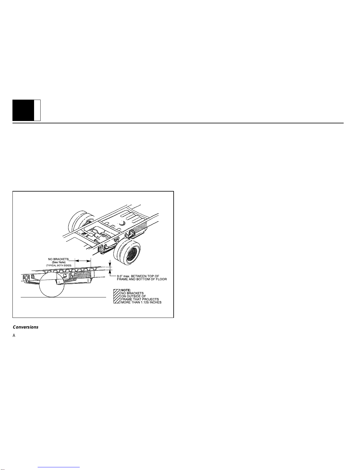
The following statement applies to P 30042 (school bus) model only
The fuel system for the school bus chassis is certified to FMVSS 301 Barrier Perfor-
mancerequirementsbasedonabodyfloorheightnotexceed3”abovethetopofframe.
The 3” maximum dimension is to be measured from the bottom surface of the interior
bodyfloortothetopoftheframe. Theheightofanycrosssupportsandspacersbetween
thebottomofthefloorsurfaceandthetop offramearenottoexceedthis3”dimension.
PAGE
2
P32/42 C
HASSIS
P32/42 Rev. 12/98
No body support brackets that project more than 1.125” outside of the frame are to be
attached to the frame rail adjacent to the area of the fuel tank.
1. Any body installed by a subsequent manufacturer is mounted securely to ab-
sorb loads and prevent movement relative to the frame which could cause any
fuel system component to be punctured, separated or otherwise damaged
when tested to the applicable procedures of FMVSS 301.
2. No installed components or vehicle modifications by a subsequent manufac-
turer impinge on or cause distortion to the fuel system with sufficient energy to
puncture, separate. or otherwise damage the fuel system when tested to the
applicable procedures of FMVSS 301. Care should be taken that the structur-
al integrity of the vehicle is restored following any structural modifications.
ÉÉÉ
ÉÉÉ
ÉÉÉ
ÉÉÉ
Conversions
Added bodies must be securely fastened to the basic vehicle structure. Do not attach
through side rails, but bolt securely through rail flange at floor and added reinforcing
plates. A minimum of 10_departure angle should be maintained if frame and/or body
is extended.
Chassis
Asshownonthechassisdrawings,therelationshipofthedashpanel,brakepedal,clutch
bracketandsteering columnmustbemaintained toensureproperoperation ofbrakes
and steering.
Bodystructuremustbeprovidedtofirmlysupportthesteeringcolumnandbrakepedal
braceintheforeandaftdirectionandlaterallysothattheangulardimensionalgeometry
shownon thechassis drawingis preserved. Onall “P”truck singleaxle models,provi-
sionsare incorporatedin thedash toe, andframe assemblyfor bodyassembly attach-
ments. It is imperative that the body assembly structure be integrated to the chassis
throughtheabovepartstoensurevehiclestructuralintegrity. Ifthisdesigncriteriaisnot
adheredtobythebodybuilders,GeneralMotorsCorporationcannotberesponsibleor
liableforchassiswarrantyresultingfrominadequateattachmentofthebodyorthechas-
sis.
Bodyunderside mustinclude innerfenders sothat engine compartment is adequately
shielded from wheel splash.
The following statement applies to P 30032 model only.
Thefrontcrossmemberextensionmustnotbeusedasabumper. BodyBuilder’sbum-
pershould beattached tothe frontcrossmember directlyopposite theside railsand to
thefrontcrossmemberoutboardofthesiderailsasrequired. ABSmoduleprotectorex-
tension must be maintained or replaced by equivalent part.
The following statement applies to P 30042 model only.
Ifthestandardfrontbumperisnotused,theBodyBuilder’sbumpershouldbeattached
to the side rails and outboard of the side rails as required. ABS module protector bar
must be maintained or replaced by equivalent part.
If the body builder installs seating other than that supplied with vehicle, it is the body
builder’s responsibility to ensure that the seating and restraint systems comply with
FMVSSrequirements. The restraintsystemssupplied withthe vehicleweredesigned
toaccommodatetheseatingreference pointsandseattraveloftheoriginalequipment
seats only.
Air Conditioning
For additional information refer to
Engine - Section 6.
NOTE: Air conditioning systems using R-134A refrigerant are equipped with metric
fittings to prevent interchange with R-12 refrigerant components. Do not
interchange R-134A components, refrigerant oil or service equipment with
R-12 components, refrigerant oil or service equipment.

PAGE
3
P32/42 C
HASSIS
P32/42 Rev. 12/98
Section 2 – Frame
Holedrilling,welding,modifications,oralterationstotheframeassemblyaretherespon-
sibilityofpersonsperformingthese operations. Thesesameindividualsassumecom-
pleteresponsibilityforframeassemblyreliability,performanceafteralterationsandcom-
pliance to applicable FMVSS requirements.
Thefollowingproceduresandspecificprecautionaryinstructionsarerecommendedfor
properinstallationofspecialbodies and/orequipmentonGMframes. Failuretofollow
these recommendations could result in serious damage to the basic vehicle.
Flanges
Do not drill holes in frame flanges:
DWithin 20 mm (0.75 in.) of radius tangent and 25 mm (1.0 in.) of raw edge.
DLarger than 12 mm (0.50 in.).
DCloser to each other than twice the hole diameter.
Holes
Holes to mount brackets, supports, and out-riggers must be drilled in the vertical side
rail web with the following restrictions:
DMaterialbetweenedgeofholeandinsideofupperorlowerflangemustnotbeless
than 37 mm (1.50 in.) for low carbon steel (36,000 PSI yield).
DTheminimumedgedistancebetweenanytwo(2)holesmustbelargerthantwice
the diameter of the larger hole.
DNo holes should exceed 20 mm (0.75 in.) in diameter.
DAll holes should be drilled in the frame using appropriate drilling practice and
safety precautions.
Welding
CAUTION: Fuel tank and fuel lines must be drained and all vapors purged to ensure
non-combustible mixture before any welding, brazing or soldering.
When welding low carbon steel side rails, crossmembers and brackets (32,000 or
36,000 PSI yield strength), emphasis is placed upon weld application techniques to
avoid stress risers that may adversely affect frame operating stresses.
Whenwelding is performedanywhere on thevehicle, precautionary measuresshould
be taken to prevent damage to electrical system wiring, front suspension air cylinders
orcomponents. Priortoanywelding,partsorcomponentswhichcouldbedamagedby
excessive temperatures must be removed or adequately shielded; the battery cables
shouldbedisconnectedatthebattery. Alsopriortowelding,theareato be weldedand
surroundingareamust becleanedofall frameprotectivecoating. Afterwelding, when
partsarecool,carefullyinspectwiringandelectricalcomponentsforshortsorotherdam-
agewhichcoulddrawexcessivecurrentsandpossiblycauseanelectricalsystemshort
whenthebattery isreconnected. Applyprotectivecoating toareaswhere coatingwas
removed.
Alterations
Ifthewheelbase ismodifiedthealterer musttakeresponsibilityfor compliancewithaf-
fectedmotorvehiclesafetystandardsandforwarrantyonitemssuchasdriveshafts,uni-
versal joints, center bearings and rear transmission tailshaft, transmission case frac-
tures, output shaft bushings, bearings, brakes, fuel systems and any other related
componentfailures. WheelbasemodificationscanaffecttheoperationoftheABSsys-
temandmayaltervehiclebrakingstabilityandorcompliancewithFMVSS105.Addition-
ally,thecustomermustbealerted inthemodifier’sownersmanualthatpartsforthere-
worked area are not available through the General Motors service parts system.
Shear Plate Attachments
Attachmentsof shearplates should beaccomplished byusing existing manufacturing
holesalreadyavailableintheframesiderails. Manufacturingholes,normally16mmin
diameter,areconsistentlyplacedalongtheframesidememberinthecenteroftheweb
on each frame.
Whenadditionalholesarerequiredforshearplateattachment,theyshouldbenolarger
than 20 mm (0.75 in.) in diameter. Holes are to be drilled no closer than 63.5 mm (2.5
in.)apart. Forholesdrilledforwardoftherearaxle,centersaretobenocloserthan63.5
mm(2.5in.)from thetoporbottom flanges andnocloserthan 89mm(3.5in.)from any
suspensionattachments. Forframeholesdrilledrearwardoftherearaxle, holecenters
aretobenocloserthan51mm(2.0in.)fromthetoporbottomflangeandnocloserthan
89 mm (3.5 in.) from suspension attachments.
No additional holes or notching of either top or bottom frame flanges is allowed.

PAGE
4
P32/42 C
HASSIS
P32/42 Rev. 12/98
Bodytie-downholesshouldonlybedrilledintopflangenolargerthan0.76indiameter;
centerlineofholesshouldbe1.0to1.12in.fromthewebsideoftheframerail. Minimum
distance between edges of the holes should be approximately 2.0 in.
Trailer Towing
TheIncompleteVehicleDocumentalsospecifiesthattheCGlocation bewithincertain
limits for proper brake balance, and may be more restrictive than the data mentioned
above. The Body Builder must use all appropriate data.
NOTE: Failure to keep body and payload CG at least 26” forward of centerline of rear
axle will result in degradation of trailer towing capacity. Consult with your Body
Builder/Final Stage Manufacturer to determine maximum tongue load for your
vehicle.
Section 3 – Front Suspension
Seechassisdatainformationforclearancesandassistanceincalculatingtrimheights.
Clearanceshouldbeprovidedforthetireusedwhileinfulljounce(upwardtravel)against
metal stops and at full left-hand and right-hand turn. The envelopes will be provided
upon request. See
Section 5 - Brakes
.
Allowance for the tire chain clearance shown on a maximum grown tire must allow for
(1.66in.)clearancetothesidesofthetireand(2.5in.)tothetopofthetire. Besuresuffi-
cientclearanceisprovidedforsuspension,axleandtire andwheelinfullverticaltravel
(up and down).
NOTE: Notification to the consumer may be required in certain states if tire chains
cannot be used.
Vehicles equipped with 3650 lbs. low height independent front suspension (IFS). The
urethaneaircylindersmust bemaintainedat70psi. Ifthevehicleisalsoequippedwith
option 9Q6, right side air cylinder should be set at 50 psi instead of 70 psi. Vehicles
equippedwith4500and5000lbs.independentfrontsuspension(IFS)urethaneaircylin-
dersmustbemaintainedat50PSI;with5500lbs.independentfrontsuspension,aircyl-
indersmustbemaintainedat90psi. Aircylinderswhenprovidedmustbeshieldeddur-
ing welding operations.
Since there is a large variation in completed vehicle front weight due to differences in
body weight and equipment, the front suspension alignment (caster, camber and toe)
mustbecheckedandresetifnecessaryafterthevehicleiscompleted. Thesuspension
must be reset by the Body Builder if it is found that the setting’s do not conform to the
specifications as outlined in the “P” Chassis Service Manual. On P 30042 trucks with
I-beams, camber and caster is designed into the axle/suspension and cannot be ad-
justed.
See Truck Service Manual for complete alignment procedure, specifications under
“Diagnosis and Front Alignment” section.
The following statement applies to P 30042 models with I-beam front axle.
Thefront crossmember steeringgear attachment isa weldment. Under noconditions
maytheflangesbecutornotchedoutinanymanner. Anyalterationwouldseverelyaf-
fect steering attachment capabilities.
Section 4 – Rear Suspension
Clearancetobodyshouldbeprovidedforthesuspension,axle,driveshaftandtiresun-
der the following conditions: (1) Axle in full jounce against the metal-to-metal stop, (2)
Axleat4.5_rollwithonesideofaxleinfulljounceatthemetaltometalstopand(3)Axle
atdesignposition. Allowance for thetirechainclearance shownonamaximum grown
tire must allow for (1.66 in.) clearance to the sides of the tire and (2.5 in.) to the top of
thetire. Besuresufficientclearanceisprovidedforsuspension,axleandtireandwheel
in full vertical travel (up and down).
NOTE: Notification to the consumer may be required in certain states if tire chains
cannot be used.
Pipes,wiring,conduitsandanyotherrelatedcomponentsmustnotbeplacedwherethey
crossthe path ofmotion ofthe rear axle, driveshaft, axlebrake pipes,hoses, spring or
tires. Suchcrossingcouldresultinrupture, wear-through,orseparationduetonormal
axle motion.
Seechassisdatainformationforadditionalclearancesandforassistanceincalculating
trim heights.
Section 5 – Brakes
See Truck Service Manual for brake specifications.
Duetothecriticalnatureofbrakesystems,anyonemakingmodificationsoralterations
mustassumecompleteresponsibilityforsystemreliability,performanceandcertification
to FMVSS 105 or FMVSS 121.

PAGE
5
P32/42 C
HASSIS
P32/42 Rev. 12/98
Itismandatorythatnochangebemadetothebrakemaincylinderlocation,brakepedal
push rod length or pedal position.
Ensure that hydraulic brake system is free of air and hydraulic leaks. Bleed brakes if
required,followingproceduresasoutlinedintruckchassisservicemanual. Ensurethat
vacuum booster system or hydroboost system is functional and free of leaks.
Check master cylinder fluid level and fill as necessary. (Refer to Owner’s Manual)
Checkpowersteeringfluidlevelformodelsequippedwithhydroboostbrake. (Referto
Owner’s Manual)
Addedfloorcoveringorcarpetingmustnotrestrictserviceorparkingbrakepedaltravel
from released position to full pedal travel.
The body builder must provide access to brake master cylinder to enable fluid level
check and the ability to add fluid as required. Clearance to master cylinder should be
providedtoenableitseasyremovalandreplacementifeverrequired. Visualaccessto
warnings printed on master cylinder reservoir must be provided per FMVSS 105.
Thebodybuildermustalsoprovideaccesstoauto-applyparkingbrakeactuatorswitch
on all 16,500 lb. GVW chassis. Opening for service in brake shield on chassis below
drivers island must remain clear.
Nobodypartorchassis-mountedcomponentincludingwheelhouseshieldsmaybelo-
cated within 2.0 in. of brake hose routing and/or wheel speed sensor wire in all wheel
and axle positions. All exhaust system components must also have a minimum of 2.0
in.clearancetobrakehosesinclosestpositions. (Besuretoaccountforbrakehoseand
sensor wire travel with suspension).
Bodybuilderistoverifythatthebrakelightswitchandbrakewarningswitchisoperative.
This includes both the brake system differential pressure and parking brake actuator
switch. Any ABS system codes that may have been set due to the body build process
must be checked and cleared prior to customer delivery.
The following statement applies to models with B3D school bus option only.
Hydroboostsystemsareequippedwith abrakefluidflowindicator.Alarm systemmust
be completed by the body builder. Shipped in a loose parts box are a buzzer module,
time delay module and wire harness, which must be installed per instructions shipped
with the loose parts box.
Floorboardandtoepanpositioncannotbealtered,asitwillinterferewithbrakeandac-
celerator pedal movement or cause driver discomfort. The floor may be covered with
normalpad and carpeting only(except P30032/42 models). Nofloor covering should
beundertheacceleratorpedal areaitwillinterferewithacceleratorcontrol movement.
Carpetingmusthave1”minimumclearancetotheacceleratorpedalandshouldbecut-
pile only. Carpeting must be properly secured to prevent any movement.
Parking brake installation and adjustment procedure:
1. Secure vehicle in place with hoist or wheel chocks and place vehicle transmis-
sion in park position.
2. Front cable routing throughout body must have a minimum radius of 6 in. and
be protected from all moving components and sharp edges.
3. For transmission mounted parking brake:
The following applies to all P 30042 models with the exception of P 31842 & MT9
Hand lever
1. Release parking brake handle and remove cotter pin, washer and clevis pin
inserted from outboard side of vehicle. Mount handle convenient to driver
comfort range.
2. Feed cable through body and reattach to handle with clevis pin inserted from
outboard side of vehicle.
3. Readjust parking lever knob to give a definite snap-over feel (approx. 60 lbs.)
when the lever is applied. With the lever in the applied position, the forward
edge of the clevis pin head should be approximately 5/8 in. from the end of the
adjusting slot on the bracket.
4. Do not alter the drum or cable adjustment at transmission unless routine ser-
vice is required in order to obtain the desired setting above. No drag should
be present after parking brake handle is released.
The following applies to all P 30032 models and P 30042 & MT9
Foot pedal
1. Release foot pedal and remove cotter pin, washer and clevis pin inserted from
outboard side of vehicle. Mount pedal coinvent to driver comfort range.
2. Feed cable through body and reattach to handle with clevis pin inserted from
outboard side of vehicle.
3. Readjust parking brake pedal to give a firm pedal at 2-5 clicks (P 30032) and
at 8-16 clicks(P 30042 & MT9) when the pedal is applied. With the pedal in
the applied position the forward edge of the clevis pin head should be approxi-
mately 5/8 in. from the end of the adjusting slot on the bracket.
4. Do not alter the drum or cable adjustment at transmission unless routine ser-
vice is required in order to obtain the desired setting above. No drag should
be present after Parking brake is released.

PAGE
6
P32/42 C
HASSIS
P32/42 Rev. 12/98
For rear axle mounted parking brakes (P 30800, P 31100, P 31432 with out JF9):
1. Release parking brake handle and remove connector between front and inter-
mediate parking brake cables. Remove front cable from frame bracket and
floor pan assembly.
2. Feed cable and handle assembly through body and re-attach handle to body
convenient to driver’s comfort range.
3. Feed cable back into frame bracket and making sure tangs lock into position.
Place connector back on front and intermediate brake cables.
4. With lever in the applied position, turn adjusting knob to give 5/8 in. clearance
from forward edge of clevis pin head to end of adjusting slot in bracket.
5. Do not alter rear brake drum adjustment or cable equalizer unless routine ser-
vice is required in order to obtain the desired settings above.
Auxiliary Braking Systems
If add-on braking systems are installed to control either tag axle or trailer braking sys-
tems, the body builder is responsible for the integrity of the system. This may require
runningFMVSScertificationtests.AnychangetotheGVWRnecessitate,recertification
toFMVSS. Caremustbetaken toassurethatflowrateofthe brakefluidisnotaffected
bythemodification,asthiscouldreducetheeffectivenessoftheABSsystem. Therec-
ommendationsoftheauxiliarybrakedevicemanufactureshouldbefollowedinmaking
themodifications. Formostsystemsthatrequireatap-inisbestdoneneartherearaxle
ofthe vehicle. Thisallowsany proportioningofthe rearbrakes to becommunicated to
theauxiliarybrakes. Thistap-inshouldnotrequiremorethan.02cu.in.offluid,andbe
capableofwithstandingpressuresupto3000psi. Auxiliarybrakes mustbecapableof
takingtheproportionofthebrakingload,forwhich,theyaredesignedtoprovideforthe
overall vehicle (combination) irrespective of fade or other operating effects.
Section 6 – Engine
For additional information refer to
Section 1 – Body.
Air conditioning and auxiliary belt-driven equipment installation recommendations:
Noalterationsor additionstothe accessorydrivebelt systemwillbe warrantedonser-
pentine belt systems.
Theserpentinebelttypeofdriveisdesignedasatotalsystem,incorporatingasinglepoly
V-belt and an automatic tensioner. In this type of system, degrees of pulley wrap, belt
tension,andpulleyalignmentareverycriticalfactors. Modificationisnotrecommended.
Duetothecriticalnatureoftheacceleratorsystem,anyonemakingmodificationsoral-
terationsassumescompleteresponsibilityforsystemreliability,performanceandcom-
pliancetoFMVSS124. Cautionmustbeexercisedsothattheacceleratorcableisprop-
erly routed. Specifications are as follows:
DRoutecabletomaximizeallbendradii. Innocaseshouldbendradiibelessthan
3 in. (76 mm).
DMinimum distance from exhaust manifold to be 6.0 in. (150 mm), unless a heat
shield is provided.
DDo not use accelerator cable or clips to route wires, harnesses or other cables.
Cablesheath mustbeclipped soas nottopinch innercable. Cable mustnotbe
loose in clip allowing sheath to move when accelerator pedal is applied and
released.
DCable must not be subjected to kinking or routing across any sharp edges.
DCable routing must be perpendicular to the surface of the front-of-dash at the
dashfitting. Noobjectsorroutingsshouldforcecabletohaveabendatthedash
fitting. Flexible components (hoses, wires, conduits, etc. ) must not be routed
within 2.0 in. (50 mm) of moving parts or accelerator linkage unless routing is
positively controlled.
DCaution must be taken so that the accelerator pedal remains properly located.
Guidelines for accelerator pedal locations are as follows:
— Ensure that the accelerator can freely operate from idle to wide-open throttle
position and return. Make sure that the pedal will not hang up on any nearby
items such as carpets, floor, screws, wiring harnesses, etc. Engine cover
should have at least one inch (25 mm) clearance to side of accelerator pedal
withthecarpetmatinstalled. Nofloorcoveringshouldbeinstalledunderpedal
area.
— Accelerator to brake pedal relationship has been designed to provide mini-
mum driver movement and should not be altered in any way.
Gasolineengineinductionand/orignitionsystemiscertifiedincompliancewiththeFed-
eralVehicleEmissionStandards. Anyalterations tothesystemsorcomponentscould
void compliance and render the vehicle illegal. System includes:
DFuelsystem–SequentialportfuelInjection(SPFI),centralportinjector(CPI)and
associated tubes, hoses and pipes, air cleaner outside air hose, fuel pump and
inlet manifold and fuel vapor canister.
DExhaust system.
DIgnitionsystemdistributorandinitialsparktimingsetting,sparkplugs,sparkplug
wires.

PAGE
7
P32/42 C
HASSIS
P32/42 Rev. 12/98
DCrankcase ventilation system.
Diesel engine induction and injector pump system is certified to be in compliance with
theFederalVehicleEmissionStandardsand/orNoiseStandards. Anyalterationstothe
systemorcomponentscouldvoidcomplianceandrenderthevehicleillegal. Systemin-
cludes:
DFuelsystem – Injectionpump, injectorlinesand injectors,fuelreturn hosesand
pipes,aircleaner,outsideairhose,fuelpump,fuelfilter,fuelheaterassemblyand
intake manifold.
DExhaust system.
DCrankcase pressure regulation system.
DExternalengine components suchas aircleaner,crankcase pressureregulator
valve, alternator, injection pipes, fuel return hoses from injectors, exhaust
manifolds,oil fillpipe, etc.mustbe providedwith sufficientclearanceforengine
roll and torque.
DWhenavehicleisequippedwithaelectronicfuelinjection(EFI)engine,ithasan
engine control module ECM/PCM/TCM or VCM. This ECM/PCM/TCM or VCM
must be maintained at a temperature below 185_F at all times. This is most
essentialifthevehicleisputthroughapaintbakingprocess.TheECM/PCM/TCM
orVCM willbecome inoperativeif itstemperatureexceeds 185_F. Therefore, it
isrecommendedthattemporaryinsulationbeplacedaroundtheECM/PCM/TCM
orVCMduring thetimethevehicle isinapaint ovenorundergoinganother high
temperature process.
Enginestartinginstructionlabellocation. Labelshouldbeinstalled2in.abovedriver’s
sunvisor bracket and 2 1/2 in. to the left of the right hand bracket.
The following statement applies to models with remote mounted air cleaners:
TheBodyBuildermustinstalltheairinletductsuchthatitprovidescooldryairtotheair
cleaner. Radiator baffling must be provided to prevent recirculation of air through the
radiator. The air inlet must be shielded from water and snow that may come from the
road, tires and through the grille.
Theair cleanerposition and ductingbetween theair cleanerand engineshould notbe
modified.
The following applies to P models with L29/L31/L35 engines:
TherelationshipoftheaircleanerassemblytotheMassAirFlowsensor(MAF)asposi-
tionedbytheaircleanerelbowcannotbealtered. TheMAFsensorblackelectronicmod-
ule must remain 30_forward of vertical.
The following statement applies to P 30032 models with a 6.5L turbo diesel engine.
CAUTION: Do not run the engine with the air cleaner or ducting to the turbo removed.
Serious personal injury or damage to the engine could result.
Apply a Caution label on the turbo inlet ducting.
Apply Starting Fluid Warning label in a visible area near air intake duct inlet.
RefertoinformationintheLoose PartsBoxforlabelingandairinletductpart numbers.
Section 7 – Transmission
Lightdutymodelsequippedwithmanualtransmissionhaveaclutch-operatedstartsafe-
tyswitch. Startershould operatewhenevertheignition isturnedtostartand theclutch
isfullydepressed. Theclutch-operatedstartsafetyswitchisintegralwiththeclutchmas-
ter cylinder push rod. It is
not
adjustable.
Modelsequippedwithautomatictransmissionsandcolumnshiftcontrolhaveasteering
columnmountedneutral/parkstartsafetymechanicallockoutfeature,whichinterfaces
withthe steeringcolumnignition switch. Starterwillonly operatewhengear shiftlever
isin the neutralor park position. Re-adjustthe shift linkageif necessaryas outlined in
the Truck Service Manual.
Transmission shiftcable must berouted andclipped properlyto avoid contact withhot
surfaces such as exhaust manifold or EGR pipe.
NOTE: Remove the shift cable clearance tag from the EGR tube after shift cable
routing.
Modelsequippedwithbrake-transmissionshiftinterlock(BTSI)mustfullyapplytheregu-
lar brakes before you can shift from park when the ignition key is in the run position.
Modelsequippedwithmanualtransmissionuseahydraulicclutchactuator. Checkfluid
levelas outlined inthe vehicleownersmanual. Attach manualtransmissionshiftlever
boot to floor using four 11514843 screws or equivalent.
It is mandatory that no change be made to the clutch master cylinder location, clutch
master cylinder push rod length, or pedal position.
Afterinstallation ofthe body,vehicles withautomatic transmissionsshould havethe shift
linkage checked and adjusted if necessary as outlined in the Truck Service Manual.

PAGE
8
P32/42 C
HASSIS
P32/42 Rev. 12/98
Shift Cables
DControlcablesshouldbesupportedoranchoredtopreventsagwhensuspended
overhead and to prevent movement where the routing bends.
DOn long control runs the conduit should be clamped to supporting structure at
least every 48 inches.
DSupports should be placed at the end of the straight runs, and not in the middle
of a bend.
DCare must be taken that the clamps do not collapse the conduit and increase
control friction.
DControlsshould berouted sothat theywill avoidrubbing, pinchingand extreme
heat, cold or vibration.
DBend radius to be 6.0 in. minimum.
Section 8 – Fuel and Exhaust
Fuel Systems
Any body installed must be mounted securely to absorb loads and prevent movement
relativetotheframewhichcouldcauseanyfuelsystemcomponenttobepunctured,sep-
aratedorotherwisedamagedwhentestedtotheapplicableproceduresofFMVSS301.
Nootherinstalled componentsormodificationsare allowedwhichcouldimpinge onor
causedistortiontothefuelsystemwithsufficientenergytopuncture,separateorother-
wisedamagethefuelsystemwhentestedtotheapplicableproceduresofFMVSS301.
Duetothecriticalnatureofthefuelsystem,anyonemakingmodificationsoralterations
totheexistingsystem,exceptasspecifiedintheIncompleteVehicleDocumentorinthis
manual, must assume complete responsibility for the systems reliability, performance
and compliance to FMVSS 301.
Assemblyofanyfuelsystem componentsmayrequireapplicationofa lubricanttopre-
vent contamination of the fuel system, only GM lubricant 9985784 may be used.
Thefuelevaporativeemissioncontrolequipmentiscertifiedtobeincompliancewiththe
FederalandCaliforniaVehicleEmissionStandards. Metalfuellinesandfueltankshave
asurfacecoatingtoreducecorrosiononinsideandoutsidesurfacestocomplywithuse-
fulliferequirements. Allfuelhosesaremadeofalowpermeationmultilayermaterialto
complywithenhancedevaporativeemissionrequirements. Anyalterationstosystems
orcomponentsincludingmaterials,hoselengthsandtheirlocation,exceptasdescribed
in the fuel fill system modifications section, could void compliance.
The system includes:
DFueltank,fuellevelsender,fuelfillandventhosesandpipes,emissioncanisters,
fuel feed, fuel return and vapor lines, purge control solenoids, fuel fill cap and
canister vent solenoid.
For these reasons,
NO ALTERATION OF THE FUEL SYSTEM IS RECOMMENDED
Temporary Tank
Thetemporaryfuelcontainermustbereplacedwithapermanentfueltankpriortoplac-
ingthevehicleintouse. Thereplacementtanksupplierand/orbodybuilderisresponsi-
ble for certifying evaporative emissions.
The following statement applies to motorhome chassis only.
The unit is fueled during shipping (gas engines only) from a temporary fuel tank which
contains the tank unit for the main tank. The temporary tank is to be removed and
scrapped. Transfer the tankunitwithO–ringsealtothemain tank. Thefuelcapforthe
main tank filler neck is the same as on the temporary tank. Remove the tank unit hole
cover and lock ring. Discard
only
the tank unit hole cover and the lock ring. Reinstall
the seal, lock ring and the tank unit assembly.
The75gallonfueltank(RPONJ9)asreceivedhasaventedplugmarked“ForShipping
Purposes Only”. This plug is to be removed and a solid steel plug shipped in the ship
loose box must be installed in place of the plug removed.
The75gallonfueltank(RPONJ9)isprovidedwithrearshieldstoprovideprotectionfor
thedepartureangleshownonthefueltankarrangementdrawing. Anyalterationordele-
tion of these shields requires that an equivalent departure angle of protection be pro-
vided by the completed vehicle.
The following statement applies to commercial models with option B3D only.
TheCPIfuelsystemforstandardmodelsisconnectedtotheregularfueltank. Thefuel
systemforoptionB3Dgasolineanddieselschoolbusmodelsisalsoequippedthisway.
Afusible plugis included inthe looseparts box. Thismust be installedinto thetagged
hole in the tank to replace a plastic shipping plug.
Fuel Fill
Fueltankfillerpipelocationshouldbesosituatedandconstructedastopreventgasoline
vaporfromemittingtoventsofpilotflameddevicesandtobodyandenginecompartment
air inlets.

PAGE
9
P32/42 C
HASSIS
P32/42 Rev. 12/98
Itis recommendedthat whenmounting thefuelfiller pipeassembly andvent hosethat
a minimum of 3” clearance be provided to any body component to prevent contact be-
tween hoses and/or mating parts and that retention be provided to ensure routing and
preventfailureduetowearandfatigue. Fillerpipeandventlinemusthaveagravityfuel
flowtotankatall times;nofueltrapsareallowed. Alterations offuellineroutingscould
affecttheabilityofthecompletedvehicleandare,therefore,notdesirable. Thecomplete
fuel system must comply with FMVSS 301.
Ifadditionalnewhoseisrequiredwheninstallingfueltankfillerneck,thishosemustbe
suitableforusewithunleadedfuelsordieselfuelrespectivelyandmustallowthevehicle
to meet enhanced evaporative emissions requirements.
Thefuelfillinletpipeassemblyattachedtothebodymustbegroundedtotheframestruc-
ture with the ground strap and fasteners provided in the shipped loose box.
Fuel Lines
Fuel line routing precautions:
D12 in. minimum clearance to exhaust system is required or a metal shield must
be provided.
DFuellinesshouldbeclippedtochassistopreventchafing. Metalclipsmusthave
rubber or plastic liners.
DUse corrosion resistant steel tubing with short sections of approved hose to
connect components. Hose-to-tube connections should be clamped for diesel
systems. Steel tube ends should be beaded for hose retention. Fuel supply is
pressurized by an in-tank pump for CPI systems. Coupled hose or nylon
quick-connectsmustbeused. ClampedhoseisnotacceptableforCPIsystems.
All engines require a fuel return system which returns excess fuel from the injection
pumpandinjectornozzlesbacktofueltanks. Careshouldbetakenthattheselinesare
not blocked nor their hoses pinched. The engine may run poorly or stall if these lines
are restricted or blocked.
Allgasolineenginevehiclesareequippedwithfuelevaporativeemissioncontrolequip-
mentwhichiscertifiedto beincompliancewiththeFederal orapplicableCaliforniave-
hicle emission standards. Alterations to fuel tank and metering unit, lines, canister or
canisters, canister filters, canister purge control valves, relay switches, tank auxiliary
ventvalve,enginespeedcontroller,orotherdevices/systemsarethereforenotallowable
since vehicle adherence to C.A.R.B. and Federal regulations may be affected.
Diesel powered vehicles incorporate water drain provisions inthe fuel system. These
valvesareonlytobeopenedwhensiphoningwaterandcontaminantsfromthefuelsys-
tem.
Fuel Tank
Forvehicleswithfullframes,thetankmusthaveaminimumclearanceof2in.top,front,
rear and sides to body and other supports.
Tank may be pressurized with nitrogen (Do not use air with fuel in the system) to 1.25
PSImaximumtocheckforfinallineleakageorforforcingfuelthroughthesystem. Pres-
sures greater than this amount may be detrimental and affect tank durability.
The following statement applies to commercial models only.
Tapping into the main fuel supply line to get fuel for a powered motor generator is not
recommendedsincethiscouldresultinfuelstarvation,vaporlockproblemsandrunning
thefueltankdry. Itisnotpermissibletodrawfuelfromafuelreturnline. Thefuelmeter
assemblyhasaanti-siphonfeatureinthereturnlinethatpreventsfuelfrombeingdrawn
out.
The following statement applies to motorhome models only.
The40, 60&75 gallongasolinetanks willincludea fueldrawtube inthetop ofthetank
assembly. This is provided for body builders to use for generators. The body builder
should remove the pipe plug in this fitting and plumb system to the generator from this
pickuppoint. Addedauxiliarypowerunitmust usethesamefuelasthechassisengine
or a separate fuel system will be required.
Theuseofauxiliaryfueltanksisnotrecommended.
Ifanauxiliaryfueltankisadded,
the alterer must take responsibility for compliance with affected motor vehicle safety
standards. Also,ifanauxiliaryfueltankisaddedtoagasoline-poweredvehicle,thefuel
must be drawn through a pipe at the top of the tank (balance line between tanks is not
permitted).
Gasolinefueled vehiclesare nowequipped witha fuelpump returnline. If anauxiliary
tankisadded,thetankselectorvalvemustincludeareturnportwhichreturnsfueltothe
tank from which the fuel is being drawn.
Ingasolineenginesthefuelpumpislocatedinthefueltank. Thebatterymustbediscon-
nected before starting any work on the fuel system.
In the use of dual fuel systems, the vehicle operator should strictly adhere to the
manufacturer’sproceduresfor switchingfromgasoline togaseous fueloperation. Im-
properswitchingproceduresmayresultinoverheatinganddamagetotheexhaustsys-
temandthevehicle. Thegaseousfueltankshouldnotbemountedinanenclosedarea
ofthevehicle, suchasthe passengercompartment,truck, etc.,andthesystem should
beventedtotheoutsideofthevehicle. Inaddition,vehiclesconvertedtogaseousfuels
shouldnotbestoredinenclosedplacessuchasgarages. Further,GeneralMotorscau-

PAGE
10
P32/42 C
HASSIS
P32/42 Rev. 12/98
tionspurchasersthatthedesign,locationandinstallationofanytypeoffuelstoragesys-
teminvolvessignificanttechnicalandengineeringconsiderationsandthatthesestate-
ments on gaseous fuel conversions should not be interpreted to be an approval by
General Motors of any modification to the original equipment fuel system.
Conversions to gaseous fuel should be made in conformance with applicable Federal
andStateregulations. Removalofemission-controlcomponents,ortheadditionofgas-
eousfuelsystemswhichcoulddamageorreducethelongevityofthosecomponentsand
could also cause the mechanical and emission performance warranty to be voided.
Exhaust System
Particularcare shouldbe takento preventthe possibilityof exhaustfumesand carbon
monoxideexposuretovehicleoccupantsinunitscompletedbybodybuilders.Holesand
openingsthroughthefloorandallotherpartsofthebodymustbepermanentlyandade-
quately sealed by the body builder to avoid exhaust intrusion into any occupant area.
If it is necessary to changethe exhaust outlet location, the exhaust discharge must be
unobstructedand directedawayfrom occupantareas. Alteration oftheexhaust outlet
orits positionmayincrease exhaustnoiseand renderthevehicle illegalinthoseareas
with pass-by noise regulations. All vehicles >10,000 lbs. GVWR come under Federal
noiseregulations,vehicles<10,000lbs.GVWRareregulatedbyvariousstateandlocal
regulationsoftheEnvironmentalProtectionAgency;seethoseregulationsforrules,test
procedure and noise levels permitted.
Tailpipeoutletlocationmustbetestedstaticallyandwiththevehicleinmotiontoensure
that exhaust gases do not penetrate side or rear windows or under body seams and
holes. Auxiliarypowerplantsshouldalsobetestedunderthesameconditions. Tailpipe
extensionmust extend2.0to 2.5in.outboard ofbodyside panels. Tailpipeexit ahead
of rear wheels is not recommended.
Check for leaks in exhaust systems and repair as required.
Exhaust temperatures can exceed 1600_F under extreme operating conditions, with
pipesurfacetemperaturesslightlylessthanthis. Extremecaremustbeusedwhenplac-
ingbodycomponentsintheproximityoftheexhaustsystemsoasnottoexceedtherated
temperature limits of the components. Due to variants in underbody configurations of
the vehicles, we are not in a position to make recommendations on how to insulate or
design components in the proximity of the exhaust system.
Each manufacturer must make temperature checks of critical areas of his vehicle and
adjusthisdesignaccordingly,or provideshieldingtoensuresafe operationofhisbody
components.
The same can be said for the engine compartment. Obviously there will be additional
heatradiatedfromtheengine. Howmuchisretainedintheareawilldependonhowwell
thisareaisventilatedinyourindividualdesigns. Hereagain,temperaturechecksofinte-
riorareassurroundingtheengineshouldbemadetodetermineifyourinsulationisade-
quate. Thisisthesameengineeringpracticewehavefollowedonourcompletevehicles
incorporating these exhaust systems.
Exhaust system materials are selected and tested to withstand the operating environ-
ment of the vehicle. Do not modify the exhaust system in any way. The tail pipes are
made of 409 stainless steel or aluminized 409 stainless steel.
Heatshieldsaremountedtotheunderbodyand/orexhaustsystemcomponents(catalyt-
icconverter andmuffler). Shields forthe propshafthanger bearingsare alsoprovided
in some vehicles.
Section 9 – Steering
Check power steering fluid level and system operations. (Refer to Owner’s Manual)
Steering wheel and horn pad must not be altered or replaced.
The following statement applies to motorhome chassis only.
Steeringwheelandshaftmustbelocatedandsupportedasshownonthebodybuilders
drawing.
Section 10 – Tires/Wheels
Check wheel lug nuts for proper torque; specifications are provided in the Owner’s
Manual.
Substitutionoftiresof greatercapacitythanthoseofferedasoriginalequipment byve-
hiclemanufacturerisnotapprovedforuseonoriginalequipmentwheels. Anyusageof
higher capacity tires must be accompanied by higher capacity wheels. However, the
wheel offset and distance from centerline of rim to wheel mounting face must be the
sameasthereplacedoriginalequipmentwheeltoensureproperwheelbearingloading
and clearance of tires to body and chassis components.
IncreasingtireandwheelcapacitydoesnotnecessarilyincreasevehicleGVWratings.
Itisrecommendedthattirechainclearanceguideline,J683fromtheSocietyofAutomo-
tive Engineers be adhered to in designing rear wheelhouse clearance.
Checktiresandinflatetorecommendedtirepressureaccordingtothetirepressureinfor-
mationdisplayedonthecertification/tirelabelprovidedwiththevehiclebeforeshipment
of vehicle from Body builder.
Any substitution of tires may affect Speedometer/Odometer accuracy.

PAGE
11
P32/42 C
HASSIS
P32/42 Rev. 12/98
Ifthebodybuilderinstallswheelcoversonthevehicle,ventedcoversmustbeused. The
minimumvent area isto bethe greaterof 34in.2 or 90%of theoriginal vehicle’swheel
vent zone. Air flow through the wheel vent and cover vent must be direct.
Section 12 – Electrical Battery and Battery Cables
Thevehiclebatteryshouldbelocatedandpositionedtomakeuseoftheexistingbattery
cables.Ifthebatteryrequiresrelocationandlongercablesarerequired,aproportionate-
lylargergaugewiremustbeused. Ifinrelocatingthebatterythenegativegroundcable
isattachedtoframerail,acableofsimilargaugebeprovidedbetweentheframerailand
the engine. This is required due to the heavy electrical loads imposed by the starting
circuit. To ensure proper operation of the battery cables the following chart on length,
gauge and materials must be strictly adhered to:
Combined Length of Positive and Negative
Cable Gauge Cable in Inches (Copper)
4 66
2 107
0 170
Ifthebatteryrequiresrelocationintheenginecompartment,theOEMsuppliedgenera-
torwithflat-compensatedregulatormustbereplacedwithageneratorwithtemperature
compensatedregulatorto regulatesystemvoltagecompatiblewith underhoodbattery
temperatures.
Underhood Battery Location
OEM Part No. Substitute Part No.
10480170 (105 A) 10480168 (105 A)
10480267 (124 A) 10480255 (124 A)
If the battery is relocated in the engine compartment without replacing generator as
statedabove,itwilleffectthebatterylifeandwillbereducedby50%oftheaveragebat-
tery life.
Battery Installation
The battery and cable installation, provided by the body upfitter, must comply with the
followingguidelines.Non-compliancemayresultinafailureofthevehicleelectricalcom-
ponent system, the shutdown of the engine, loss of backupbrake system, loss of ABS
braking control, and the possibility of fire.
DThe cables must not contact any sharp edge(s), in either the normal (stored) or
slid (maintenance) position (school bus application).
DThe cables must not be bent in a radius of smaller than 10 times the cable
diameter. Insulation failure can occur if this happens.
DThecablemustbesupported byclipsspacedatadistanceofnot morethan450
mm. Inthis clipping, theyshall nothavea freemovementthat willallowrubbing
on any vehicle component, either fixed or moveable.
DAll clips used must be of the rubber-lined type, not rubber dipped.
DDonotsplicethebatterycables. Cablemodificationscanresultinvehiclestarting
problems and loss of other key systems.
DThecables must beclipped tothe battery traysuch thatthe cable pullloads are
not transferred into the battery posts due to slide tray movement. Failure to do
so can result in loose terminals, poor starting and battery failure. Battery acid
leakage could result around posts not properly relieved of strain.
DThe cable attachments at the battery terminal must not cause undue strain at
theseconnections.Thereshouldbenosharpbendsinthecablesadjacenttothe
connections. The cables should be routed down from the terminals rather than
horizontally from the terminals to prevent a lever action that may loosen
connections. Terminal corrosion inhibitors and other coatings should not be
applied to the sealed electrical contact areas. Terminal torque of the sealed
terminal shall be 10/20 N-M freedom, 14/20 N-M linehaul.
DMounting Base (Tray):
Thetrayshouldbeofsubstantialmaterial(minimum1.75mmthickorsufficiently
reinforced)toresistflexingandcracking. Thetraymustprovidefirm,continuous
support of the battery and not amplify vibration levels. There must be no
protrusionsorprojectionsinthetrayormountingsthatwoulddamagethebattery.
Cantileveredmountings arenotrecommended andthe trayshouldbe mounted
flat so as not to aggravate electrolyte spillage or lead fatigue. A rounded lip of
adequateheighttoensurestiffnessandretentionshouldbeprovidedaroundthe
perimeter of the tray. With the battery mounted in a vehicle, a static force of 22
kg applied to a 6.54 sq. cm. area at any corner should not move the battery any
more than .25 mm.
DFreedom Battery:
The hold-down must be able to prevent the battery movement relative to the
mountingbaseorhold-down.Torqueatthebatteryhold-downshallbe15/20N-m
(133-177lbs.-in)at thebaseclampor 2.3/4.5N-m(20-40lbs.-in.) atthetop bar.
Abottomhold-downcentrallylocatedatthesidesofthebatteryisrecommended.
DLinehaul Battery:
A tight, secure hold-down is essential. Hold-down brackets must retain the
batteryata22G-3millisecondshockloading. Atophold-downshouldbespaced

PAGE
12
P32/42 C
HASSIS
P32/42 Rev. 12/98
aminimumof15mmfromterminalpoststoavoidpossiblegroundpaths. Ifatop
hold-down is used, a non-corrosive, non-conductive coating is desirable.
Location:
The battery should be located in a well ventilated area where a temperature
build-updoesnotoccur.Thelocationshouldalsoprovideprotectiontothebattery
to prevent damage from foreign objects. The ends of the battery in the area of
theventportsshouldbefreeofobstructionssothatthegassesgeneratedduring
charging can be freely dissipated into the atmosphere.
DAccessibility:
Thehold-downshouldbeconvenient fortoolsandhandssothat personalinjury
does not occur. There should be clearance at the insulated and grounded
terminalssothatwrenchescanbeusedsothataccidentalgroundsorshortswill
notoccur. Terminalpolaritymarkings,warninglabelsandtesthydrometershould
be visible. The battery “ground” connection must be readily accessible for
disconnection, as required for vehicle electrical service requirements.
DTilt Angles:
Fornormalvehicleoperation(atGVW),thebatteryshouldnotbetilted(0_). For
installationorremoval,itshouldnotbenecessarytotiportiltthebatteryinexcess
of40_. This isto prevent acidspillage. For shortduration vehicle shipment,do
not tilt the battery more than 19_from the horizontal.
DTemperature:
The temperature of the electrolyte should not exceed 52_C. Infrequent peak
temperaturesto75_Ccanbetoleratedinsoaksituationsonly. Shieldingmaybe
required to protect the battery from a source of excessive heat.
DBattery Trays:
Batterytraysaresuppliedwiththechassis. Inthecaseofmotorhomesanddiesel
school busses, the trays are secured to the frame rail (for shipping only).
The trays shipped on the rails may be relocated to other areas on the vehicle,
keeping in mind the recommendations noted above.
DBattery Storage:
Today’s vehicles have several electronic devices which result in very small but
continuouscurrentdrainsontheirbatteries,commonlyreferredtoas“parasitic”
loads. Vehicles that are not used for an extended period of time may develop
extremely discharged and/or permanently damaged batteries resulting from
theseparasitic loads. Dischargedbatteries canfreeze attemperatures ashigh
as 20_F causing permanent damage.
To alleviate this condition, check to make sure green dot is visible, recharge as
necessary,thendisconnectthenegativebatterycableonvehicleswhicharenot
goingtobeinservicewithina30dayperiod. Ifthisisnotpossible,batteriesshould
be recharged periodically (every 30-60 days) until the green dot is visible.
NOTE: The ignition switch must be off when connecting or disconnecting battery
cables or hangers (jumper cables). Failure to do so may overstress or damage
the ECM/PCM/TCM, VCM, ABS or other electronic components.
Modifications/add-onwiringmustbecarefullyreviewedtoensurecompatibilitywiththe
basevehiclewiringbyreviewingthevehicleelectricalsystemmechanizationprints,de-
tailed harness prints and Delphi–Packard electric division connection system design
qualityguidelines. Duetothewiderangeofmodificationsthatmayberequiredforvoca-
tionalneeds, itisnot feasibleforthe O.E.M.totake intoaccount allpotentialrevisions.
Forthisreason,anypersonmodifyingexistingvehiclewiringmustassumeresponsibility
thattherevisionshavenotdegradedtheelectricalsystemperformance. Anyadd-onwir-
ingmustbeproperlyfusedandroutedtopreventcut,pinch,andchafeproblems,aswell
asavoidexposuretoexcessiveheat. Caremustbeexercisedthatexistingvehicleinter-
facesdonothavetheircurrentloadcapabilitiesexceeded,andthattherespectivecon-
troldevices are notoverloaded. Added wiresize should beat leastas large as the the
wire to which it is attaching in order for fuse protection to be maintained.
APackardelectricwiringrepairkitisavailablethroughKent–Moore(GMP/N12085264,
Kent–Moore P/N J38125-4). This kit contains instructions, tools and components for
makingrepairs to wiringharness components. Thiskit would alsogreatly assistin ac-
complishingnecessary add-on wiringsuch asbody marker lamps,so thatsystem reli-
ability/durability is maintained.
ElectricalwiringcomponentscanbeobtainedthroughyourauthorizedGMdealer.Many
Packard Electric components are also available through Pioneer Standard Company
(1-800-PACKARD). Pioneermayalsobeabletoassistinmakingnecessarywiringaddi-
tions by providing custom wiring stubs or jumpers to your specifications.
Fusible Link Repair Procedure:
1. Cut damaged fusible link from wiring harness assembly splice.
2. Strip insulation from harness wire as required to splice on new fusible link.
3. Fabricate a new fusible link wire approximately 6 to 8 in. long from the same
wire size as the original link. (Acceptable fusible link material will be imprinted
with the wire size and the wording to identify it as fusible link. Fusible link
cable is not the same as normal vehicle wiring.)
4. Terminate fusible link harness wire with a suitable compression splice clip, and
solder with an electrical grade rosin core solder. Wrap splice area with tape to
provide electrical insulation, as well as mechanical strain relief at the splice.
5. Strip, terminate, solder, and insulate remaining end of fusible link with ap-
propriate termination to be compatible with the rest of the electrical system.
6. For further information, refer to the instruction manual in the wiring repair kit
referenced elsewhere in this section.

PAGE
13
P32/42 C
HASSIS
P32/42 Rev. 12/98
Section 13 – Heating/Cooling
To provide satisfactory engine cooling, the following conditions must be met:
DThe minimum frontal area for the Chevrolet/GMC is 360 square inches, to be
directlyin front ofthe radiator. Ifthe vehiclegrille areaisnot directlyin linewith
the radiator face, filler panels between the radiator and grille must be used to
directtheairthroughtheradiator. Anyareaoutsideofa45_anglefromtheedge
of the radiator should not be considered as grille open area, for cooling.
DThe grille opening should be ‘open’ in configuration. Small holes for the grille
openingtendtorestrictairflowmorethanlargeholesalthoughbothmayhavethe
same frontal area.
DCoolingcanbeimprovedbyinsertingfillerpanelsbetweentheouterverticalside
edges of the radiator and grille. In addition, a filler panel should be fitted
horizontallyfromthebottomoftheradiatorouttothebottomofthegrille. Thiswill
preventairfromby-passingtheradiatorandexitingthroughthefrontwheelhouse
area or under the radiator. These panels will force the air through the radiator.
DAflexibleair-tightsealmustbeprovidedbetweentheupperradiatorsupportand
the body to aid idle cooling and prevent hot air recirculation. The seal assures
thatincoming ‘ramair’ mustgo throughthe radiatorcore ratherthanby passing
the radiator core (going up and over the core).
DBug screens should be avoided if at all possible. If conditions require a bug
screen, motor home owners are advised to be alert to possible engine
overheating problems as well as temperature changes. The screen’s mesh
should be-at most-half as dense as that of standard household screening.
Household screening will create an overheating condition. The bug screen
should be removed immediately upon leaving the bug infested area.
Do not install any internal flow restrictors.
The 3 way or ‘H’ valve is not required in the heater system for port fuel injected
engines.
Coolant Recovery Bottle:
1. Mount the coolant recovery bottle in an easily accessible area with the top
approximately the same height as the radiator fill cap. The bottle must be sup-
ported by the two attaching embossments at the top and also by the rib at the
bottom of the bottle to prevent failure of the unit. You may use the supplied
bracket and rework as required for proper mounting.
2. Hose may be cut to proper length as required to reach from the radiator over-
flow tube just under the radiator cap to the larger diameter nipple on the cool-
ant recovery bottle cap. Retain the hose by using two 5/8 in. hose clamps.
3. For the initial fill of the coolant recovery bottle, fill to the “hot” mark on the
bottle. This allows the system to initially purge itself and maintain the proper
coolant level. Refer to the Owner’s Manual for proper mixture.
The following statement applies to P 30042 models only.
Radiatorsupport assembly isnot astructural member. No bodymounting supportsor
other attachments used for structural purposes are to be fastened to radiator support
assembly. Example: Hornsshould not be mounted on the radiator supportassembly.
The following statement applies to P 30032/42 diesel models only.
Fordieselengines,ade-aerationtank isaddedtothecoolingsystem. Thissystemwill
passnormalcombustiongasesoutofthecoolingsystem. Thede-aerationcoolingsys-
tem includes a de-aeration tank, radiator, fitting and hoses.
Heater
Be sure to add coolant to system after adding capacity to system (heaters).
Ifaheaterisinstalledonthevehicle,ableedervalvemustbeaddedtotheheaterreturn
lineattheheaterinthereturnlinetotheengine,valvemustbeatthispointsinceitisthe
highestpointinthesystem. Thepurposeforthebleederistobleedairfromthesystem
aftertheheaterandlinesareinstalled. Failingtodosocancausewaterpumpsealdam-
age.
Proper bleed procedure are as follows:
1. Open bleeder valve and fill cooling system with coolant until coolant exits
valve.
2. Close valve and continue filling system until full.
3. With radiator cap off, start engine and run for approximately two minutes at
medium RPM.
4. Shut engine off, open bleeder valve and fill system as above and run again for
two minutes.
5. Shut engine off, top off coolant and install radiator cap.
6. Check for leaks at connections.
PAGE
14
P32/42 C
HASSIS
P32/42 Rev. 12/98
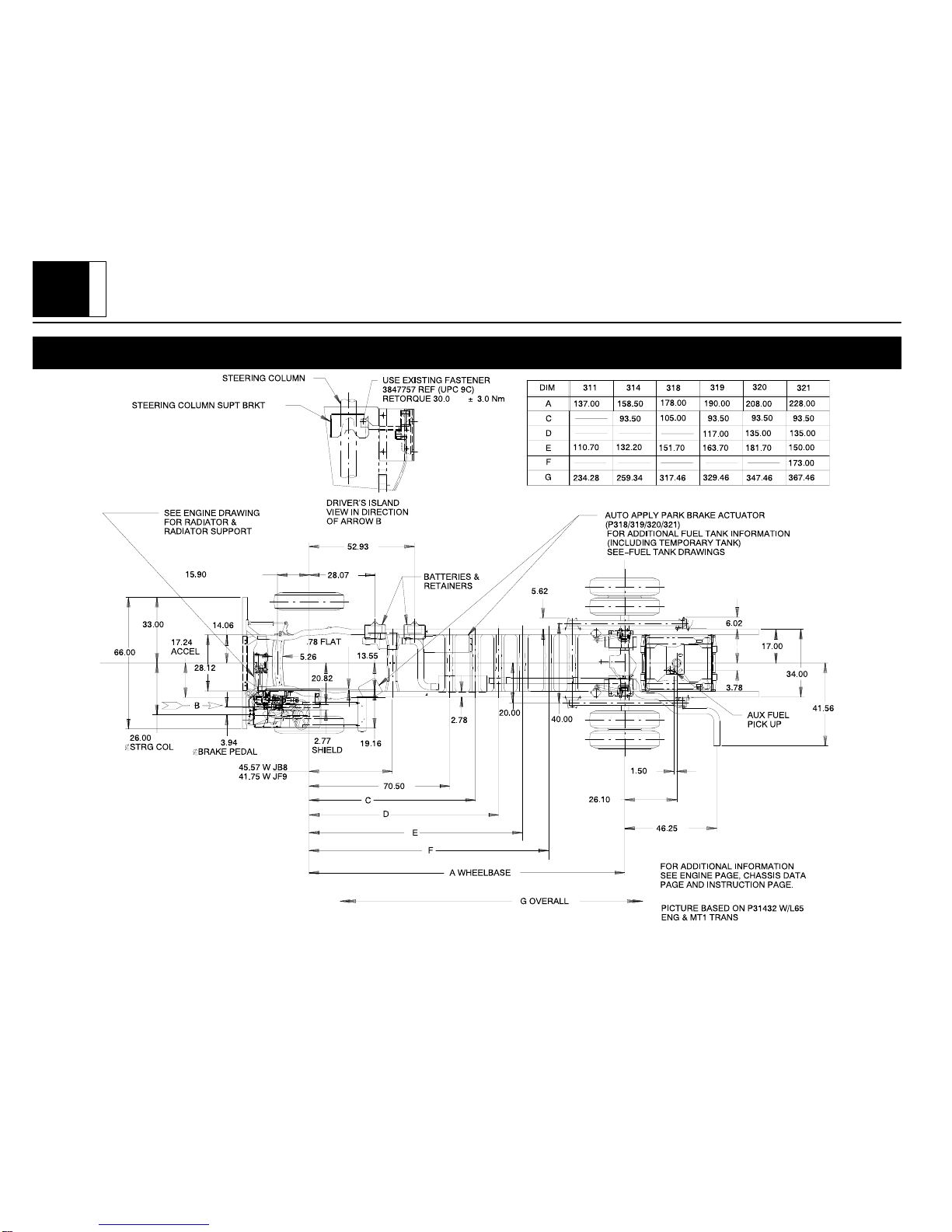
P 30032 General Arrangement, Diesel Engine, Option L65, 6.5L Turbo HO
PAGE
15
P32/42 C
HASSIS
P32/42 Rev. 12/98
P 30032 General Arrangement, Diesel Engine, Option L65, 6.5L Turbo HO
PAGE
16
P32/42 C
HASSIS
P32/42 Rev. 12/98
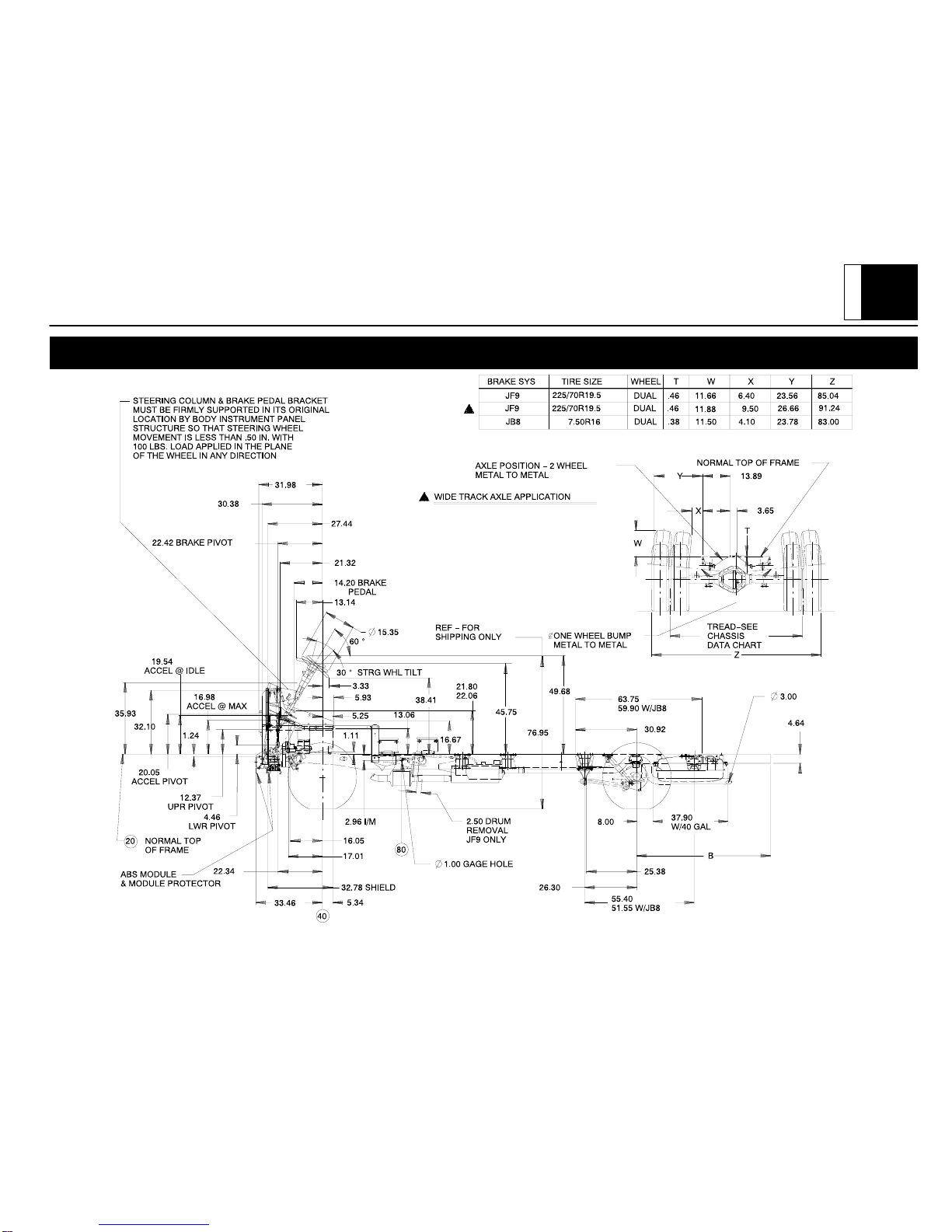
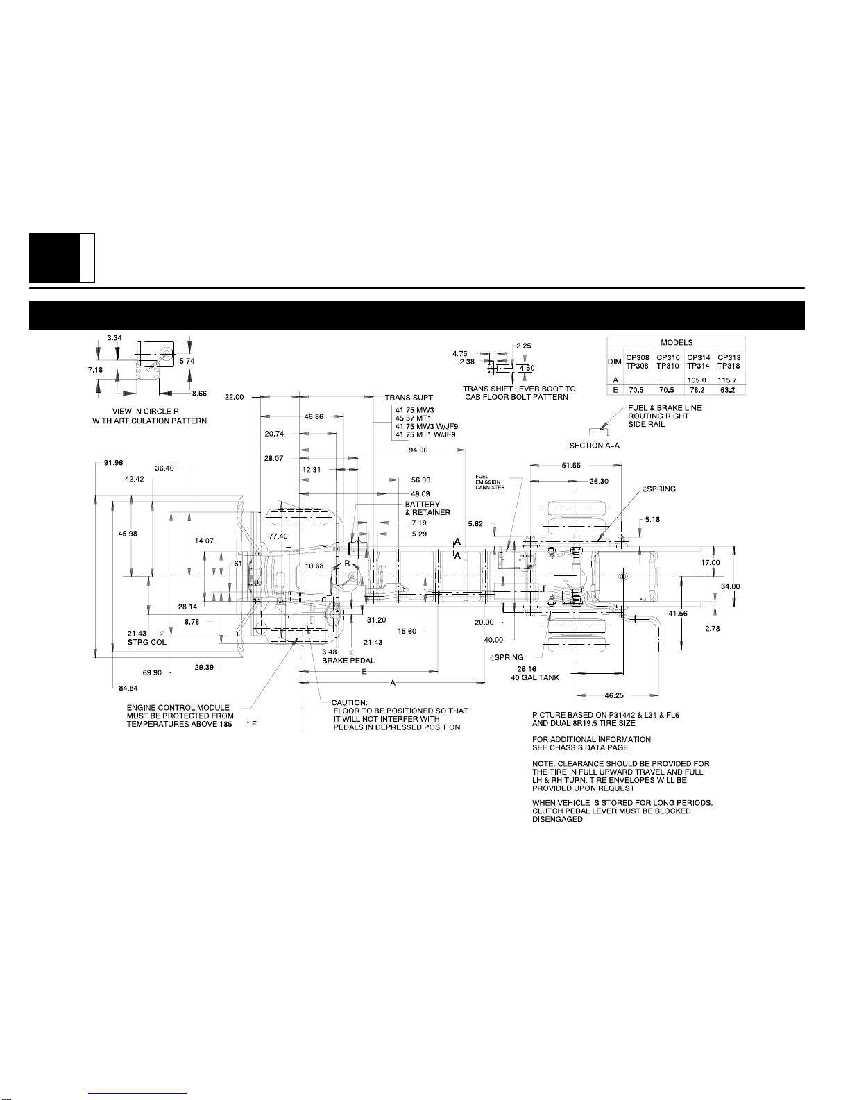
P 30042 General Arrangement, Diesel Engine, Option L57, 6.5L HO w/FL6 Independent Front Suspension
PAGE
17
P32/42 C
HASSIS
P32/42 Rev. 12/98
P 30042 General Arrangement, Diesel Engine, Option L57, 6.5L HO w/FL6 Independent Front Suspension

PAGE
18
P32/42 C
HASSIS
P32/42 Rev. 12/98
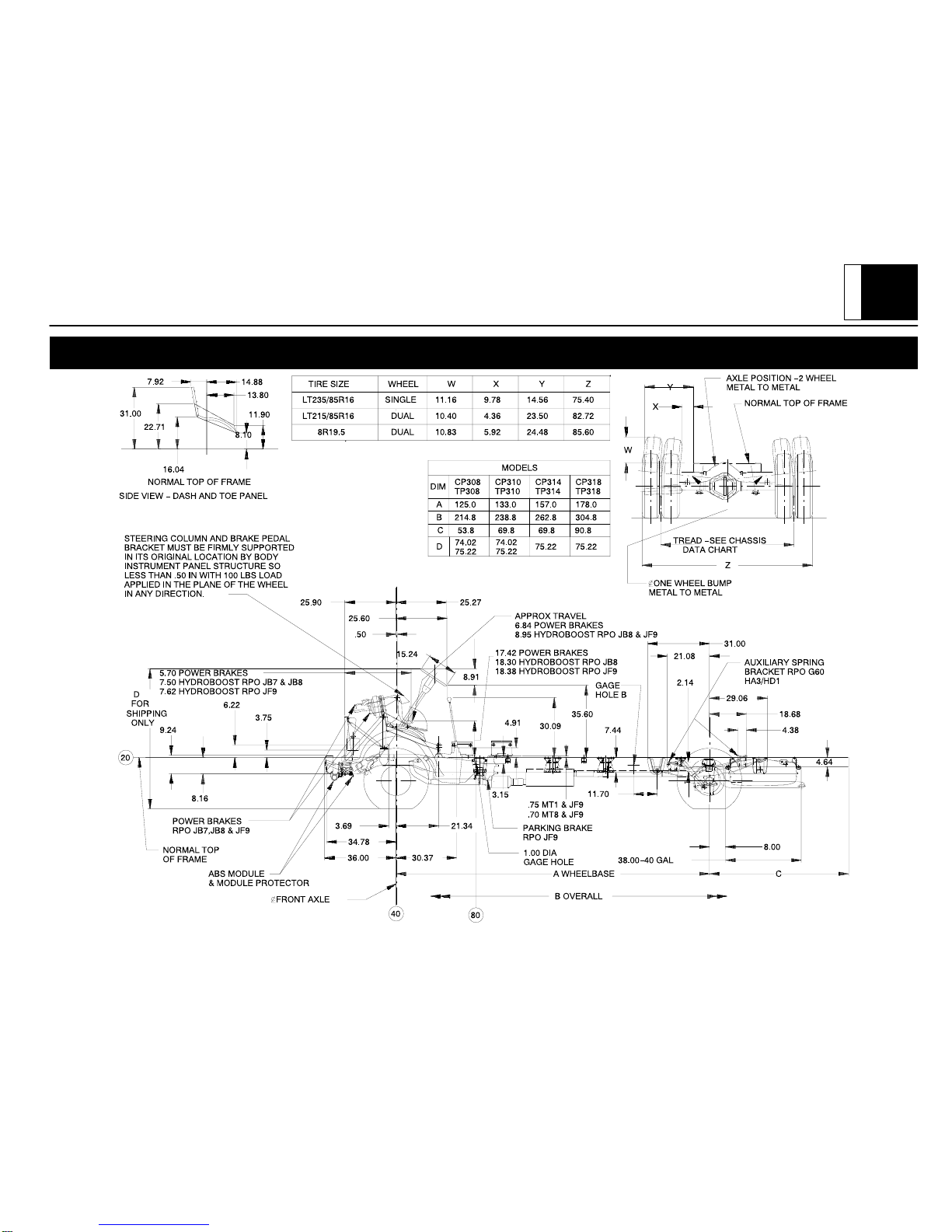
P 30042 General Arrangement, Gas Engine, Option L31, 5.7L V8 w/FK4, I-Beam Front Suspension
PAGE
19
P32/42 C
HASSIS
P32/42 Rev. 12/98
P 30042 General Arrangement, Gas Engine, Option L31, 5.7L V8 w/FK4 I–Beam Front Suspension, Option FK4
PAGE
20
P32/42 C
HASSIS
P32/42 Rev. 12/98
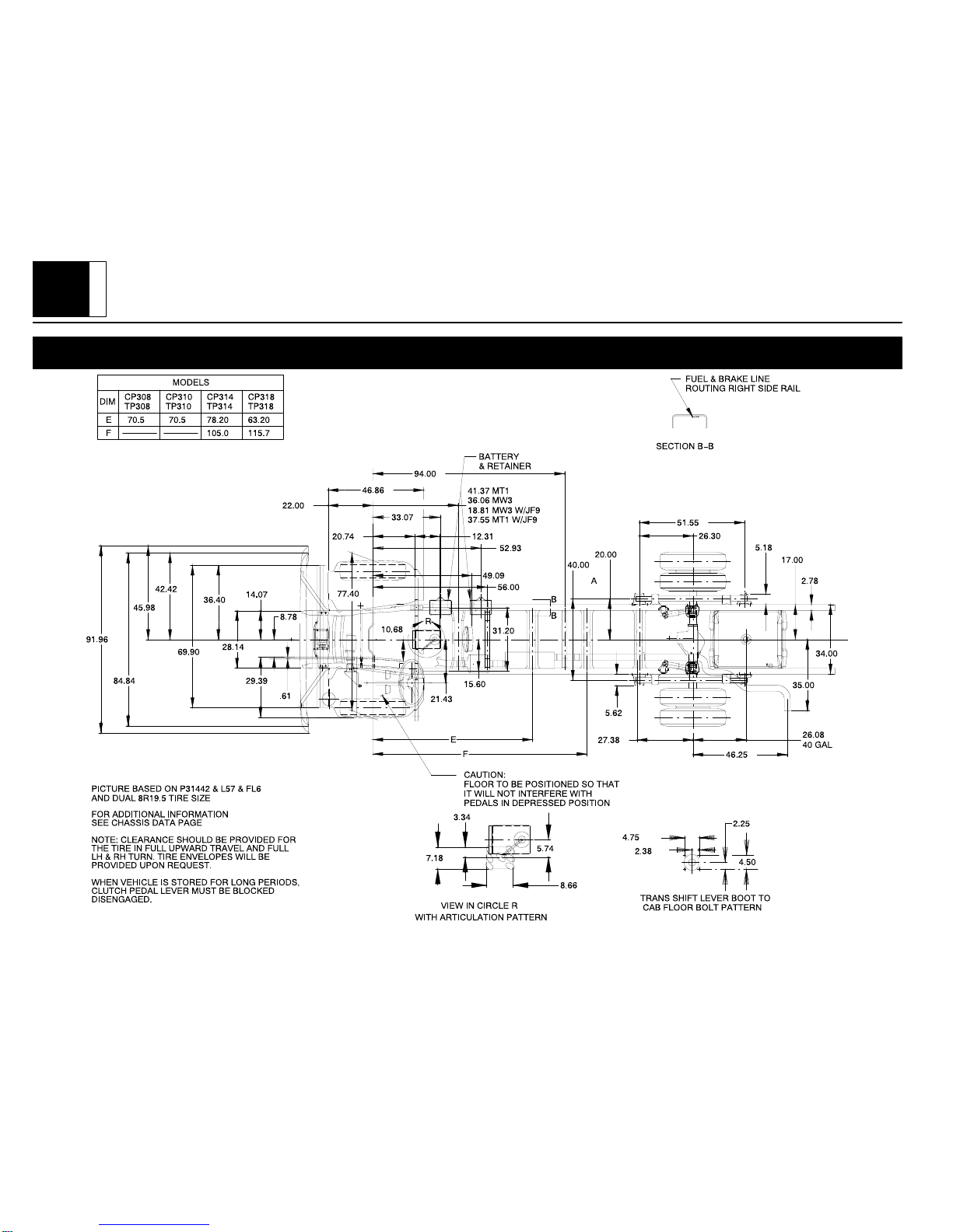
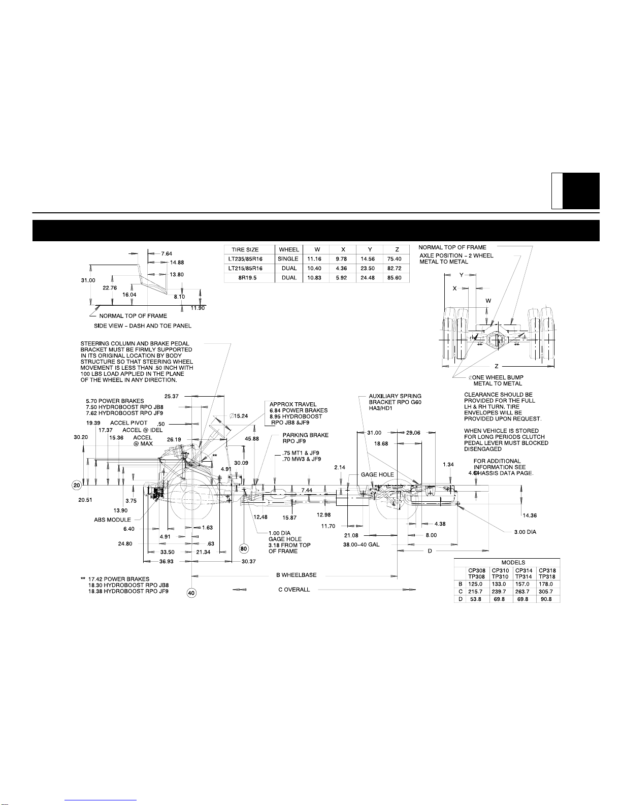
P 30042 General Arrangement, Gas Engine, Option L31, 5.7L V8, w/FL6 Independent Front Suspension
This manual suits for next models
1
Table of contents
Popular Automobile Accessories manuals by other brands

Turtle
Turtle Tirol Assembly and service instructions

American International
American International TOYK932GB quick guide

Mont Blanc
Mont Blanc FK204 Fitting instructions

Altera
Altera SIGNO 044 298 manual

EMOVE
EMOVE EM203 manual

Fiamma
Fiamma SUN VIEW SIDE CARAVANSTORE/F35 Installation and usage instructions


