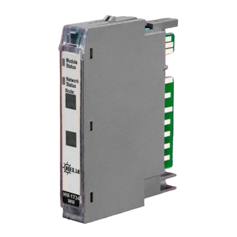
Helm HM1525 User manual

Model HM1525
10/05/2018
Instruction Manual
October, 2018
1769 Weigh Scale
Module
Helm Instrument Company, Inc.
361 West Dussel Drive
Maumee, Ohio 43537 USA
419/ 893-4356
Fax: 419/ 893-1371
www.helminstrument.com

HM1525 Weigh Scale Module
Page 2
Solid state equipment has operational characteristics differing from those
of electromechanical equipment. “Safety Guidelines for the Application,
Installation and Maintenance of Solid State Controls” (Allen-Bradley
Publication SGI-1.1) describes some important differences between solid
state equipment and hard-wired electromechanical devices. Because of
this difference, and also because of the wide variety of uses for solid
state equipment, all persons responsible for applying this equipment
must satisfy themselves that each intended application of this equipment
is acceptable.
In no event will the Allen-Bradley Company or Helm Instrument
Company be responsible or liable for indirect or consequential damages
resulting from the use or application of this equipment.
The examples and diagrams in this manual are included solely for
illustrative purposes. Because of the many variables and requirements
associated with any particular installation, the Allen-Bradley Company or
Helm Instrument Company cannot assume responsibility or liability for
actual use based on the examples and diagrams.
No patent liability is assumed by Allen-Bradley Company or Helm
Instrument Company with respect to use of information, circuits,
equipment, or software described in this manual.
Reproduction of the contents of this manual, in whole or in part, without
written permission of the Allen-Bradley Company and Helm Instrument
Company is prohibited.
Throughout this manual we use note to make you aware of safety
considerations.
ATTENTION: Identifies information about practices or
circumstances that can lead to property damage.
Identifies information that is especially important for
successful application and understanding of the product.
Attentions help you:
identify a hazard
avoid the hazard
recognize the consequences
ATTENTION: Please check power supply ratings
before proceeding! Each tonnage module
consumes (+24, 50mA +5, 66mA). Be sure to not
overload the power supply.
Important User
Information

HM1525 Weigh Scale Module
Page 3
Read this preface to familiarize yourself with the rest of this manual. This
preface covers the following topics:
who should use this manual
the purpose of this manual
terms and abbreviations
conventions used in this manual
Allen-Bradley support
Use this manual if you are responsible for the design, installation, programming,
or maintenance of an automation control system that used Allen-Bradley small
logic controllers.
You should understand electronic process control and be able to interpret the
ladder logic instructions required to generate the electronic signals that control
your application. If you do not, contact your local Allen-Bradley representative for
the proper training before using this product.
This manual is a learning and reference guide for the Helm Weigh Scale Module.
It contains the information you need to install, wire, and use the module.
Purpose of
This Manual
Who Should
Use this
Manual
Preface

HM1525 Weigh Scale Module
Page 4

HM1525 Weigh Scale Module
Page 5

HM1525 Weigh Scale Module
Page 6

HM1525 Weigh Scale Module
Page 7

HM1525 Weigh Scale Module
Page 8

HM1525 Weigh Scale Module
Page 9
OUTPUT TAG DESCRIPTIONS
CALMODE
Used for initial installation. All math is disabled, weigh value is not scaled, leaving raw A/D value.
WEIGH MODE
Factory cal setting 100,000 counts = 2MV/V
CLEAR TARE CH1/CH2 Bit
Clears internal tare value for “zero state”.
Useful when troubleshooting load cell wiring or other failures.
TARE CH1/CH2
Sets A/D value to zero.
READ ADTRIM BIT
(HELM Factory setting only).
CH1/CH2 AUTO TUNE BITS
Set to “1” when in auto cal mode
Reference/cal weight on before setting bit
READ SCALE SET BIT
Set to “1” to verify CH1/CH2 scale sets
ENABLE FILTER BITS
Set to “1” to enable 60/50 h2 filter
CH1/CH2 FILTER ON BIT
Set to “1” to enable filter
Set to “0” to disable filter

HM1525 Weigh Scale Module
Page 10
OUTPUT TAG DESCRIPTIONS
MSF BITS –(Motion Stabilization Filter)
Used for applications with constant or static type loads to keep display value stable.
MSF1_2 (1 count up –2 counts down).
MSF2_4
MSF4_8
MSF5_10
Set one bit only.
ZERO-DEAD-BAND BITS
Useful for Auto-Tare functions with production runs.
Set only one bit.
ZEROBAND_025 = .025% full scale
ZEROBAND_05 = .05% full scale
ZEROBAND_075 = .075% full scale
Auto tare occurs when load cell weight is at bit level or lower.
READ MV/V BIT
Check verify mV/V settings
READ CAL FACTOR BIT
Check auto cal values
SAVE TO EEPROM
Stores CH1/CH2 scale settings
AUTO CAL MODE
Set to “1” for auto cal mode
SET CH1 SCALE BIT
Set to “1” to set CH1 scale
SET CH2 SCALE BIT
Set to “1” to set CH2 scale

HM1525 Weigh Scale Module
Page 11
REQUIRED CONTROLLER TAGS
CH1/CH2 SCALE SET AND AUTOCAL REFERANCE
CH1_SCALE_MOD1
Full scale setting for CH1, CH2
Value is determined by capacity of load cell and by resolution required.
Example: 10KG = 10,000
GET WEIGH VALUE CH1
CH1_WEIGHT_MOD1
CH2_WEIGHT_MOD1
Reports measured weigh value in RUN mode.
Reports raw A/D count value in CAL mode.
SET AVERAGE SAMPLE COUNT
SMAPLE_SET_MOD1
Set number of samples to take for average type filter.
SET mV/V CH1, CH2
CH1_MV_V MOD1
CH2_MV_V MOD1
CH1/CH2 MV_V Settings
Enter 2000 for 2.0 mV/V
Actual value is from load cell specification.
FILTER TIME _MOD1
FILTER_TIME_MOD1
Each count = 1 msec
50 h2: 20 msec = 20
60 h2: 16 msec = 16

HM1525 Weigh Scale Module
Page 12
Specifications - HM1734-WM Strain Gage Input Module
Module Location 1734-TOP (screw terminal) or 1734-TOPS (spring loaded terminal)
Type of input Strain Gage (350 ohm, 700 ohm)
Gage Excitation Voltage 5 Volt
Input Impedance 5.11 meg. ohm
Display Resolution Up to .0025% of full scale
Module Accuracy Dependent on Load Cell Specification
Module Update Time Software selectable from 2ms to 100ms
Number of Channels 2 (isolated)
A/D Conversion Method Successive Approximation - 24 bit
Normal Mode Rejection:
(between +/- input) 116DB CMRR
Amplifier Bandwidth 200 kHz
Calibration Software Selectable
Isolation: 500 VDC continuous between inputs
and chassis ground, and between input
and backplane
LED indicators 2 LED's for Power and Alarm
Recommended Cable Strain Gage Cable (Helm part number 6117)
Operating Temperatures 0°C to 60°C (32°F to 140°F)
Emissions CISPR 11
Group 1, Class A
Pointbus Current 5V @ 72ma
External Power 24V @ 19.5ma
Dimensions 2.21H x 0.47W x 2.97L (Millimeters 56H x 12W x 75.5L)

HM1525 Weigh Scale Module
Page 13
AUTO-CAL PROCEDURE
1) Set known weight for channel at scale parameter.
2) Tare-0 (with no weight on cell/scale).
3) Apply known load (test weight) to load cells/ scale.
4) Set AUTOCAL bit on for CH1 (CH2 if applicable).
5) Turn bit off before removing known weight.
6) To ensure accuracy, repeat the steps above.
7) Toggle “save to eeprom” bit

HM1525 Weigh Scale Module
Page 14
SETTING UP HM1525WM MODULE
Step #1
Add module to project as following:
HM1525WM MODULE PROPERTIES
General Tab Settings
Connection Tab Settings

HM1525 Weigh Scale Module
Page 15
Step #2
Open “Template” file
Copy all controller tags
Open project file
Paste controller tags
Duplicates may be created, delete them now
Step #3
Open “Template” file
Copy add-on instruction “HM1525WM”
Open project file
Paste add-on instruction in add-on’s section

HM1525 Weigh Scale Module
Page 16
Step #4
Open “Template” file
Copy weightmodule1
Open project
Paste weighmodule1
Check program tag here should be as
Example

HM1525 Weigh Scale Module
Page 17
Step #5
Check routine for entries

HM1525 Weigh Scale Module
Page 18
Data Map for HM1734-WM on Ethernet/IP
OUTPUT TAGS
Description
Output_bits_mod1.0
bit
Set Cal Mode Bit
Output_bits_mod1.1
bit
Set Run Mode Bit
Output_bits_mod1.2
bit
Ch1 Clear Tare Bit (momentary)
Output_bits_mod1.3
bit
Ch1 Tare Bit (momentary)
Output_bits_mod1.4
bit
Ch2 Clear Tare
Output_bits_mod1.5
bit
Ch2 Tare
Output_bits_mod1.6
bit
Read mV/V sets
Output_bits_mod1.7
bit
Read cal factor
Output_bits_mod1.8
bit
Save to eeprom
Output_bits_mod1.9
bit
Read adtrim
Output_bits_mod1.10
bit
Auto cal mode
Output_bits_mod1.11
bit
Set Ch1 scale
Output_bits_mod1.12
bit
Set Ch2 scale
Output_bits_mod1.13
bit
Ch1 auto-tune
Output_bits_mod1.14
bit
Ch2 auto-tune
Output_bits_mod1.15
bit
Read scale sets
Parameter_bits_mod1.0
BOOL
Msf 1-2
Parameter _bits_mod1.1
BOOL
Msf 2-4
Parameter _bits_mod1.2
BOOL
Msf 4-8
Parameter _bits_mod1.3
BOOL
Msf 5-10
Parameter _bits_mod1.4
BOOL
Msf 6-12
Parameter _bits_mod1.5
BOOL
Msf 7-13
Parameter _bits_mod1.6
BOOL
Msf 8-14
Parameter _bits_mod1.7
BOOL
Reserved
Parameter _bits_mod1.8
BOOL
Zero band 25
Parameter _bits_mod1.9
BOOL
Zero band 50
Parameter _bits_mod1.10
BOOL
Zero band 75
Parameter _bits_mod1.11
BOOL
Enable filter
Parameter _bits_mod1.12
BOOL
Ch1 filter on
Parameter _bits_mod1.13
BOOL
Reserved
Parameter _bits_mod1.14
BOOL
Reserved
Parameter _bits_mod1.15
BOOL
Ch2 filter on
Data Map for HM1734-WM on Ethernet/IP

HM1525 Weigh Scale Module
Page 19
Required Controller Tags
Data Tags Name
Data Type
Ch1_mv_v_mod1
INT
Ch1_scale_mod1
DINT
Ch1_weigh_mod1
DINT
Ch2_mv_v_mod1
INT
Ch2_scale_mod1
DINT
Ch2_weight_mod1
DINT
Filter_time_mod1
INT
Mode_set_bits_mod1
INT
Parameter_bits_mod1
INT
Sample_set_mod1
INT

HM1525 Weigh Scale Module
Page 20
The following documents contain information that may be helpful to you as you use Allen-Bradley SLC
products. To obtain a copy of any of the Allen-Bradley documents listed, contact your local Allen-Bradley
office or distributor.
For
Read this Document
Document
Number
CompactLogix 5370 L1 Programmable
Automation Controllers
CompactLogix 5370 L1 Programmable
Automation Controllers
1769-PP012
An overview for the MicroLogixTM
Programmable Controllers
MicroLogix 1500 Programmable Controllers
1764-UM001A-US-P
A description on how to install and use your
MicroLogix Programmable Controller
MicroLogix 1500 Programmable Controller
Base Units Installation Instructions and
Wiring Diagrams
1764-IN001A-ML-P
A description on how to install the processor
into the MicroLogix 1500 Base unit.
MicroLogix 1500 Processor Installation
Instructions
1764-IN002A-ML-P
Selecting Discrete Input/Output Modules
Compact Discrete Input/Output Modules
Technical Data
1769-2.1
View power usage of expansion modules to
determine power supply requirements
Expansion Modules System Qualifier
RA Website Download
End Cap Installation
Compact I/O End Caps/Terminators
Installation Instructions
1769-5.16
A complete listing of current Automation
Group documentation, including ordering
instructions. Also indicates whether the
documents are available on CD-ROM or in
multi-languages
Automation Group Publication Index
SD499
A glossary of industrial automation terms
and abbreviations
Allen-Bradley Industrial Automation
Glossary
ICCG-7.1
An article on wire sizes and types for
grounding electrical equipment
National Electrical Code
Published by the
National Fire
Protection
Association of
Boston, MA.
Related
Documentation
Other manuals for HM1525
1
Table of contents
Other Helm Control Unit manuals
Popular Control Unit manuals by other brands

Elo TouchSystems
Elo TouchSystems DMS-SA19P-EXTME Quick installation guide
Tews Technologies
Tews Technologies TPMC866-TM-20 user manual
Atkinson Electronics
Atkinson Electronics GSCM-MINI-50 manual
Trox Technik
Trox Technik XS installation manual
Lenz
Lenz Digital Plus BM3 Information
Sierra Wireless
Sierra Wireless AirPrime WP7504 Hardware integration guide
Beta LaserMike
Beta LaserMike LASERSPEED 8000 Instruction handbook
Automationdirect.com
Automationdirect.com Productivity 2000 P2-08TD1S manual
Novanta
Novanta JADAK THINGMAGIC EL6E Getting started
Infineon
Infineon AIROC CYBLE-343072-02 manual
Pego
Pego VISION100 THR Use and maintenance manual

Sony
Sony MB0402C2 user manual
