Helmholz 700-159-3MB02 User manual

Helmholz GmbH & Co. KG | Hannberger Weg 2 | 91091 Großenseebach | Germany 24.08.2022
Phone +49 9135 7380-0 | Fax +49 9135 7380-110 | info@helmholz.de | www.helmholz.de
Quickstart Guide
PN/ModbusTCP Coupler
Order number: 700-159-3MB02
For firmware V2.00 and above
4
Version
en
5

Quickstart Guide PN/ModbusTCP Coupler | Version 4 | 24.08.2022 2
Content
1Safety instructions ................................................................................................ 3
2Introduction ......................................................................................................... 3
3Function of the PN/ModbusTCP Coupler.............................................................. 4
4Connection........................................................................................................... 4
4.1 Power supply ............................................................................................................................... 4
4.2 Network ....................................................................................................................................... 5
5Install GSDML file ................................................................................................. 5
6Data exchange concept ........................................................................................ 6
6.1 Example of a configuration ........................................................................................................... 7
6.2 Supported ModbusTCP function codes ........................................................................................ 7
7Configuration in the TIA-Portal ............................................................................ 8
7.1 Parameters of the PN/ModbusTCP Coupler .................................................................................. 8
7.2 Configure ModbusTCP modules................................................................................................. 10
7.3 Assign a PROFINET device name to the PN/ModbusTCP Coupler ................................................ 11
8Status and control via PLC program ...................................................................12
9Web interface of PN/ModbusTCP Coupler..........................................................13
10 MQTT Publisher ...............................................................................................15
10.1 MQTT Publisher Settings ............................................................................................................ 15
10.2 MQTT data format...................................................................................................................... 16
11 Firmware update ............................................................................................. 17
12 Resetting to factory settings ............................................................................ 17
13 Technical data .................................................................................................18
14 LED status information ....................................................................................19

Quickstart Guide PN/ModbusTCP Coupler | Version 4 | 24.08.2022 3
1Safety instructions
Target audience
This description is only intended for trained personnel qualified in control and automation
engineering who are familiar with the applicable national standards. For installation,
commissioning, and operation of the components, compliance with the instructions and
explanations in this operating manual is essential. The specialist personnel is to ensure that the
application or the use of the products described fulfills all safety requirements, including all applicable laws,
regulations, provisions, and standards.
Intended use
The device has a protection rating of IP 20 (open type) and must be installed in an electrical
operating room or a control box/cabinet in order to protect it against environmental
influences. To prevent unauthorized operation, the doors of control boxes/cabinets must be
closed and possibly locked during operation. The consequences of improper use may include
personal injury to the user or third parties, as well as property damage to the control system, the product,
or the environment. Use the device only as intended!.
Operation
Successful and safe operation of the device requires proper transport, storage, setup, assembly,
installation, commissioning, operation, and maintenance. Operate the device only in flawless
condition. The permissible operating conditions and performance limits (technical data) must
be adhered to. Retrofits, changes, or modifications to the device are strictly forbidden.
Security
The device is a network infrastructure component and therefore an important element in the
security consideration of a plant. When using the device, therefore, observe the relevant
recommendations to prevent unauthorized access to installations and systems.
2Introduction
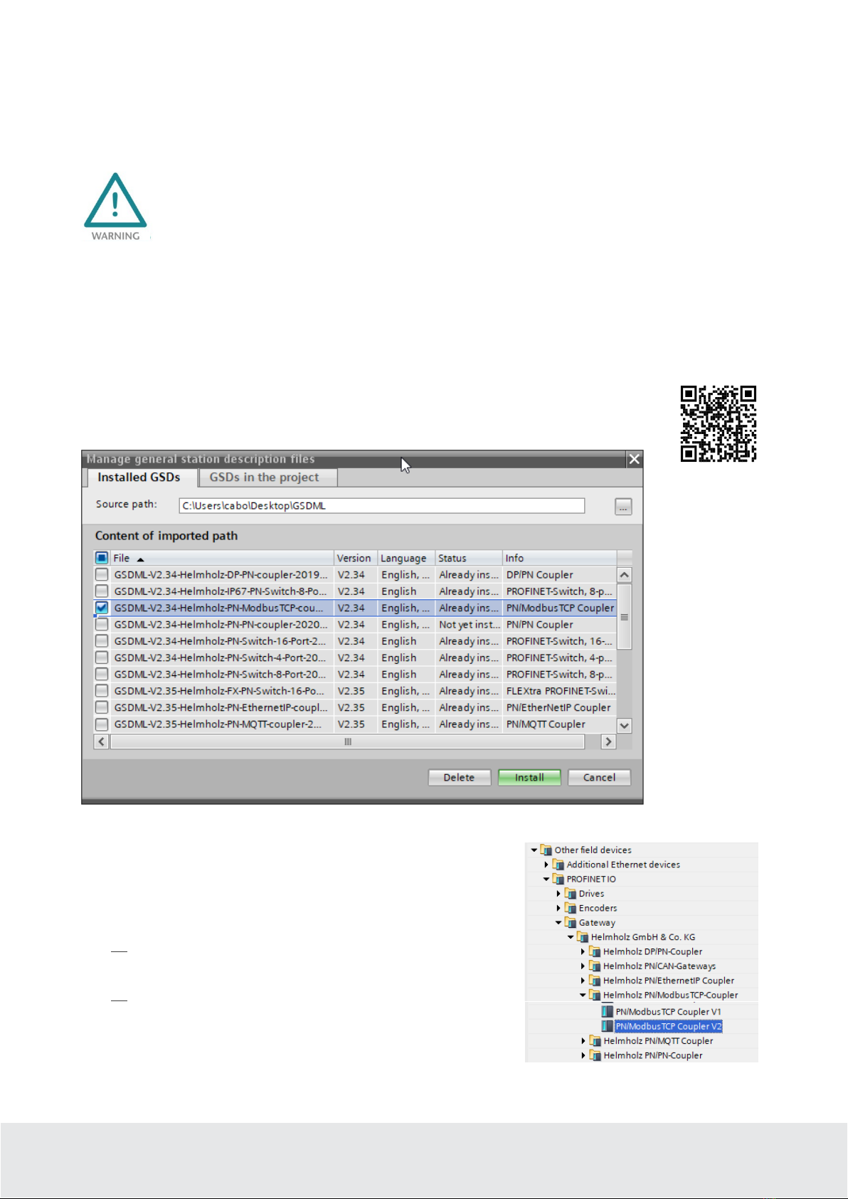
This document explains the initial commissioning of the PN/ModbusTCP
Coupler. The latest version of the document and a detailed manual can be
found at www.helmholz.de or scan the QR code directly.

Quickstart Guide PN/ModbusTCP Coupler | Version 4 | 24.08.2022 4
3Function of the PN/ModbusTCP Coupler
With the PN/ModbusTCP Coupler a simple and uncomplicated connection of a PROFINET network with
a ModbusTCP network is possible. The PN/ModbusTCP Coupler allows the data transfer between a
PROFINET controller and ModbusTCP stations.
Received input data on one of the network sides is
made available as output data to the other
network side. The IO data transfer takes place live
and as quickly as possible without additional
handling blocks.
The maximum size of the transmitted data is 1024
bytes of input/output data. Up to 300 slots for IO
modules are available.
The integration into the PLC engineering tool is
made possible by a GSDML file; special
configuration software isn’t necessary.
In addition to the PROFINET / ModbusTCP communication, the PN/ModbusTCP Coupler also makes an
MQTT Publisher available on both network sides. In this way, the values exchanged via the gateway can
also be distributed via MQTT to visualization or operating data recording systems.
4Connection
4.1 Power supply
The PN/ModbusTCP coupler must be supplied with DC 24 V at the wide-range input DC 18 ... 28 V via
the supplied connector plug. The power supply is redundant, at least one supply path PS 1 or PS 2 must
be connected.
The housing of the PN/PN Coupler is not grounded. Please connect the functional earth terminal
of the PN/PN Coupler properly to the reference potential.
The device is intended to be supplied by an isolated Limited Energy Source according to UL61010-1
(3rd ed cl. 9.4) or according to UL60950-1/UL62368-1 or Class 2 according to NEC. Please use Cu
power supply wires, AWG 28-12. Maximum length of removed insulation is 10 mm. Temperature
cable rating is 87 °C.

Quickstart Guide PN/ModbusTCP Coupler | Version 4 | 24.08.2022 5
4.2 Network
The left RJ45 sockets "X1 P1" and "X1 P2" are used to connect the PROFINET network, the right RJ45
sockets "X2 P1" and "X2 P2" are used to connect the ModbusTCP network. The ports X1 P1 and X1 P2, as
well as X2 P1 and X2 P2 are each internally connected to a switch.
The ETHERNET connections are only intended for connection to computer networks (LANs) and
must not be connected to telephone networks or telecommunication lines. The unit is to be
connected only to internal Ethernet networks without exiting a facility and being subjected to TNVs.
The interfaces X1 and X2 are logically separate networks and not physically connected. Thus, there is a
clear separation between the PROFINET network and the ModbusTCP network. A network penetration
with other functions by the PN/MQTT coupler is not possible. The configured values are exchanged in
the PN/ModbusTCP Coupler only as IO data between both network sides.
5Install GSDML file
Please download the GSDML file ("GSDML-V2.34-Helmholz-PN-ModbusTCP-coupler-
____.xml") at www.helmholz.de or scan the QR code. Install the GSDML file in the "Tools"
/ "Manage device description file (GSD)" menu in the TIA Portal.
The PN/MQTT Coupler can be found in the hardware catalog at
"Other field devices / PROFINET IO / Gateway / Helmholz GmbH
& Co. KG".
For the PN/ModbusTCP coupler with order number 700-159-
3MB02 select the "PN/ModbusTCP Coupler V2".
For the PN/ModbusTCP coupler with order number 700-159-
3MB01 select the "PN/ModbusTCP Coupler V1".

Quickstart Guide PN/ModbusTCP Coupler | Version 4 | 24.08.2022 6
6Data exchange concept
The PN/ModbusTCP Coupler is a ModbusTCP server. It receives data via ModbusTCP, which is
transferred to the IO image of the PROFINET PLC (inputs in the PLC) and provides data, which it receives
from the PROFINET PLC (outputs in the PLC).
ModbusTCP distinguishes 4 different data types:
Discrete Inputs: Input bits; written by the PROFINET PLC
Coils: Output bits or internal data bits, are read by the PROFINET PLC, but can also be written
Input Register: Input word; written by the PROFINET PLC
Holding Register: Output word or internal data word; are read by the PROFINET PLC but can also be
written
All data types are numbered from 0-65535. All data types have their own memory area in the
PN/ModbusTCP coupler:
From the point of view of ModbusTCP communication, all coils, inputs and registers are always available
in the PN/ModbusTCP coupler. So it is always possible to access all data types from address 0-65535.
Via the PROFINET configuration the ModbusTCP data can be assigned to the PLC I/O image in the slots,
which are required in the PLC program. Up to 300 slots are available in the PN/ModbusTCP coupler for
such assignments.
The following modules are available to access the ModbusTCP memory:
Discrete Inputs (PLC writes only):
•Write Discrete Inputs 1 – 32 Bytes (8 – 256 Bits)
Coils (read/write):
•Write Coils 1 - 16 Bytes (8 – 128 Bits)
•Read Coils 1 – 16 Bytes (8 – 128 Bits)
Input Register (PLC writes only):
•Write Input Register (16 Bit)

Quickstart Guide PN/ModbusTCP Coupler | Version 4 | 24.08.2022 7
Holding Registers (read/write):
•Write Holding Register (16 Bit)
•Read Holding Register (16 Bit)
All modules have as parameter the register number (Input Register, Holding Register) or the first bit
address (Discrete Inputs, Coils).
6.1 Example of a configuration
6.2 Supported ModbusTCP function codes
The PN/ModbusTCP Coupler supports the following function codes:

Quickstart Guide PN/ModbusTCP Coupler | Version 4 | 24.08.2022 8
7Configuration in the TIA-Portal
Add the PN/ModbusTCP coupler to the project and connect the coupler to the PROFINET network.
Assign a device name and check the IP address on the PROFINET network (X1) for the device.
7.1 Parameters of the PN/ModbusTCP Coupler
The parameterization of the PN/ModbusTCP Coupler can be done completely via the PROFINET
hardware configurator. However, some parameters for the ModbusTCP network (X2) can optionally also
be set via the web page, e.g. the IP address of the ModbusTCP server or the DHCP host name.

Quickstart Guide PN/ModbusTCP Coupler | Version 4 | 24.08.2022 9
ModbusTCP IP-address mode: Setting the IP address for the ModbusTCP network. Selectable are
"DHCP", "Static IP", "use IP from the web page setting".
Static IP address: If the address mode is set to "Static IP", the static IP address can be specified here.
Static IP subnet mask: If the address mode is set to "Static IP", the subnet mask can be specified here.
DHCP hostname mode: The host name of the device can be set in the PROFINET configuration or on
the web page.
DHCP hostname: DHCP name of the device. DHCP names must begin with a letter, end with a letter or
digit, and contain only letters, digits, and hyphens.
ModbusTCP port: Port on which the ModbusTCP driver listens. Port 502 is always active, even if another
port is set here.
Connection watchdog time (ms): Time in which a ModbusTCP connection is closed when there is no
more communication over that connection. Range: 1 - 65535 ms
Maximum ModbusTCP connections:Maximum number of nodes that can establish simultaneous
connections with the PN/ModbusTCP coupler.
Register for PROFINET-Status: Number of the register from which the status of the PN/ModbusTCP
coupler can be read out via ModbusTCP. Range 0-65535
Status Webpage:On which network interfaces should the web page be displayed.
MQTT Publisher Option: On which network interfaces should the MQTT Publisher be activated (see
Chap. 10).
Diagnostic at PS1/PS2 failure:In case of power supply failure at PS1/PS2 a diagnosis is sent to the PLC.

Quickstart Guide PN/ModbusTCP Coupler | Version 4 | 24.08.2022 10
7.2 Configure ModbusTCP modules
For the data exchange between the ModbusTCP memory in the coupler and the PLC EA memory up to
300 modules can be plugged in the PROFINET configuration of the coupler. Now insert the desired
modules for Discrete Inputs, Coils, Input Registers or Holding Registers into the slots.
All modules have as parameter the register number (Input Register, Holding Register) or the first bit
address (Discrete Inputs, Coils). For the Input Bits and Coils from 8 bits (1 byte) up to 256 bits (32 bytes)
can be addressed together in one slot.
Addressing of single bits is not possible via the PROFINET PLC, the smallest amount is a byte (8 Bits).
However, the bit address can start at any position in the address space of the coils or discrete inputs, so it
does not have to be divisible by 8.
Access to the same memory area by two modules is not permitted. There must be no gap in the
configuration of the slots.

Quickstart Guide PN/ModbusTCP Coupler | Version 4 | 24.08.2022 11
7.3 Assign a PROFINET device name to the PN/ModbusTCP Coupler
When the configuration of the PN/ModbusTCP Coupler in the hardware configurator of the engineering
tool is completed, it can be imported into the PLC.
In order that the PN/ModbusTCP Coupler can be found by the PROFINET controller, the PROFINET
device name must be assigned to the PN/ModbusTCP Coupler. For this use the function "Assign device
name" which you can reach with the right mouse button or in the menu Online if the PN/ModbusTCP
Coupler is selected.
With the “Update list...” button, the network can be browsed for PROFINET participants. The PROFINET
device name can be assigned to the device with “Assign name”.
The unique identification of the PN/ModbusTCP Coupler in the PROFINET network is guaranteed by the
MAC address of the device. The PROFINET MAC address can be read on the front panel of the
PN/ModbusTCP coupler on the left side at X1 ("MAC 1").
If the PN/ModbusTCP Coupler has received the correct PROFINET name, then it is recognized and
configured by the PLC. If the configuration is correct, the PROFINET "BF" LED should be off.
To set the PROFINET name, you can also use the Helmholz IPSet tool, which can be
downloaded free of charge from the Helmholz website. Scan the following QR code to
download the IPSet tool:

Quickstart Guide PN/ModbusTCP Coupler | Version 4 | 24.08.2022 12
8Status and control via PLC program
The PN/ModbusTCP Coupler provides a status and a control byte via the PROFINET input image.
Status Byte 1: Status-Bits
7 6 5 4 3 2 1 0
PROFINET
configuration
completed.
Device is ready
to operate.
-
Power supply
detected on
PS 1 (left)
Power supply
detected on
PS 2 (left)
MQTT
connection
on network
X1active
MQTT
connection
on network
X1active
ModbusTCP
network has an
active IP address
(static or obtained
via DHCP)
Network
cable
detected
Status byte 2: Number of active connections
Control byte 1: Control Bits
7 6 5 4 3 2 1 0
- - - - - -
ModbusTCP memory
reset (coils, inputs,
and registers)
Disconnect all
ModbusTCP
connections and
prevent connection
establishment
The PN/ModbusTCP coupler starts after successful PROFINET configuration and is immediately in
operation after PLC RUN. A further release via PLC program is not necessary. If the automatic start is not
desired, the PN/ModbusTCP coupler can be prevented from starting independently by setting bit 0 to 1
in the control byte during PLC startup. If the bit is later set to 0 in the PLC, the PN/ModbusTCP coupler is
immediately ready for operation.

Quickstart Guide PN/ModbusTCP Coupler | Version 4 | 24.08.2022 13
9Web interface of PN/ModbusTCP Coupler
The web interface of the PN/ModbusTCP coupler provides an overview of the status and the
configuration of the device, as well as the possibility to perform a firmware update.
Furthermore, the ModbusTCP configuration can be set in the web interface, if this is not specified by the
PROFINET configuration.
When accessing the web interface for the first time, a password must be set for the default user "admin".
The password can be adjusted subsequently in the "Account" menu.
The "Overview" web page shows the current settings and status. In the upper line there is the menu for
further web pages.
Calling the website may influence the transmission performance of the PN/ModbusTCP Coupler.

Quickstart Guide PN/ModbusTCP Coupler | Version 4 | 24.08.2022 14
The "Module config" page shows the IO
modules defined by the PROFINET
configuration. On the ModbusTCP page
the data type and the address are also
indicated. The current value is displayed in
brackets.
On the web page "ModbusTCP server settings" the IP address and the DNS name of the ModbusTCP
network interface can be set, as far as these were not fixed by the GSDML configuration.

Quickstart Guide PN/ModbusTCP Coupler | Version 4 | 24.08.2022 15
10 MQTT Publisher
The PN/ModbusTCP Coupler provides besides the PROFINET / ModbusTCP communication also a MQTT
Publisher. MQTT is a widely used and simple protocol for distributing information in large networks.
For all IO modules defined in the PROFINET configuration, the current values can now be sent by the
PN/ModbusTCP coupler via MQTT when the value changes.
The MQTT Publisher can be activated either on the PROFINET network side (X1) or on the ModbusTCP
network side (X2), depending on which network side the data is required or where the MQTT Broker is
installed. The MQTT Publisher cannot work on both network sides at the same time.
Since MQTT works slower than the priority PROFINET/Modbus TCP communication, it may be that
not all value changes are transmitted via MQTT, but always only the last value state.
10.1 MQTT Publisher Settings
To be able to distribute data via MQTT in a network, an MQTT broker is always required. The broker can
run anywhere in the network. The settings of the MQTT publishers can be specified separately for the two
network sides on the website under "MQTT".
ClientID: The name of the MQTT publisher
Username / Password: Optional username and password to login to the MQTT broker
Broker IP address: IP address of the MQTT broker
Broker TCP port: MQTT port on the MQTT broker
Keep alive (seconds): MQTT connection monitoring during inactivity
The MQTT Publisher of the PN/ModbusTCP Coupler does not provide encryption!

Quickstart Guide PN/ModbusTCP Coupler | Version 4 | 24.08.2022 16
10.2 MQTT data format
Each configured slot sends its own MQTT message. An MQTT message consists of the topic name and the
actual data value (payload). Both are usually transmitted in plain text format. The data is transmitted as
hexadecimal bytes for coils and discrete inputs or as a 16-bit decimal number for holding registers and
input registers.
The topic name is formed depending on which network - PROFINET (X1) or ModbusTCP (X2) - the
MQTT Publisher is activated on.
On both network interfaces the following MQTT topics can be read additionally:
"ClientID/Modules List": Contains the list of all topics provided by the PN/ModbusTCP coupler via the
addressed interface.
"ClientID/Status Register": Contains the value of the two status bytes.

Quickstart Guide PN/ModbusTCP Coupler | Version 4 | 24.08.2022 17
11 Firmware update
The firmware of the PN/ModbusTCP Coupler can be updated very easily via the website.
You can get the firmware from the Helmholz website with the following link:
http://www.helmholz.de/goto/700-159-3MB01#tab-software
The firmware file can be recognized by the file extension "HUF" (Helmholz Update File)
and is encrypted to protect it from modification.
A firmware update can be performed via the web interface on the "Firmware upgrade" page.
With the button "Browse" the firmware can be selected. With the button "Submit" the firmware is trans-
ferred to the PN/ModbusTCP coupler and burned. Afterwards the PN/ModbusTCP coupler executes a
reboot, and the new firmware is active.
During the update process the operation of the PN/MQTT Coupler is interrupted. Do not switch off
the device during the update process!
12 Resetting to factory settings
Resetting the PN/ModbusTCP Coupler to factory settings can be done via the web page or via the
PROFINET function.
When resetting the PN/ModbusTCP coupler, the configuration is irretrievably deleted, and the settings
are reset to the factory defaults. The firmware remains at the current status.
To reset via the website, use the button on the "Firmware upgrade" page:
To reset the PN/ModbusTCP Coupler, the Helmholz tool "IPSet" can also be used via the PROFINET
network.

Quickstart Guide PN/ModbusTCP Coupler | Version 4 | 24.08.2022 18
13 Technical data
Order no. 700-159-3MB02
Article designation PN/ModbusTCP Coupler
PROFINET interface (X1)
Connection 2x RJ45, integrated switch
Protocol PROFINET IO Device as defined in IEC 61158-6-10
Transmission rate 100 Mbit/s full duplex
I/O image size Up to 1024 Byte of input and output data
Number of configurable slots 300
Features PROFINET Conformance Class B, media redundancy (MRP-Client),
automatic addressing, Topology detection (LLDP, DCP), diagnosis alarms
MQTT interface (X2)
Connection 2x RJ45, integrated switch
Protocol ModbusTCP Server
Transmission rate 10/100 Mbit/s, full-/half duplex
Storage size 65536 Coil Bits, 65536 Discrete Input Bits, 65536 Input Register,
65536 Holding Register
Supported function codes 1, 2, 3, 4, 5, 6, 15, 16, 22, 23
Status indicator 9 LEDs function status, 8 LEDs Ethernet-status
Voltage supply DC 24 V (18 - 28 V DC)
Current draw max. 210mA
Power dissipation max. 5 W
Dimensions (D x W x H) 32,5 x 58,5 x 76 mm
Weight approx. 135 g
Certifications PROFINET Conformance Class B
Protection rating IP 20 (not evaluated by UL)
Relative humidity 95% non-condensing
Mounting position any
Ambient temperature 0° C to 60° C
Transport and storage temperature -20° C to 80° C
UL UL 61010-1 / UL 61010-2-201
Power supply DC 24 V (18 ... 28 VDC, SELV and limited energy circuit)
Pollution degree 2
Altitude Up to 2000m
Temperature cable rating 87 °C

Quickstart Guide PN/ModbusTCP Coupler | Version 4 | 24.08.2022 19
14 LED status information
X1 PROFINET (left side) X2 MQTT network (right side)
SF (red)
Off Configuration correct Configuration correct
On
There is no configuration, the configuration does not
agree with the configuration on the right side (X2),
or a diagnosis exists.
PROFINET side not configured or failed
Flashing PROFINET function "LED flashing" for finding the
device is executed
-
BF (red)
Off The device is configured The device is configured
On
The device has no configuration, the PROFINET
device name is incorrect, or there is no connection
with the PROFINET controller
No Ethernet cable plugged in or no Ethernet
connection
Flashing PROFINET function "LED flashing" for finding the
device is executed
-
MT (yellow)
Flashing A firmware update is being carried out A firmware update is being carried out
Flashing with
SF and BF
PROFINET function “LED flashing” for finding the
device is being carried out
-
PWR (green)
On PS1 Power supply present PS2 Power supply present
RUN (green)
Off Firmware or device defective. Please contact Support
On The device is ready to operate
RJ45 LEDs X1 P1/P2 und X2 P1/P2
Green (Link) Connected
Orange (Act) Data transfer at the port active
The contents of this Quick Start Guide have been checked by us so as to ensure that they match the hardware
and software described. However, we assume no liability for any existing differences, as these cannot be fully
ruled out. The information in this Quick Start Guide is, however, updated on a regular basis. When using your
purchased products, please make sure to use the latest version of this Quick Start Guide, which can be viewed
and downloaded on the Internet from www.helmholz.de.
Our products contain open source software, among others. This software is subject to the respectively relevant license
conditions. We can send you the corresponding license conditions, including a copy of the complete license text together with
the product. They are also provided in our download area of the respective products under www.helmholz.de. We also offer to
send you or any third party the complete corresponding source text of the respective open source software for an at-cost fee of
10.00 Euro as a DVD upon request. This offer is valid for a period of three years, starting from the date of product delivery.
Our customers are important to us, we are happy to receive suggestions and ideas for improvement. If you have any questions
regarding the use of the product, please contact Helmholz Support by phone or send an e-mail to support@helmholz.de.
All trademarks shown or mentioned in this document are the property of their respective owners or manufacturers.
The representation and naming serve exclusively to explain the use and setting options of the products documented here.
Table of contents
Other Helmholz Adapter manuals

Helmholz
Helmholz SSW7-RK512 User manual

Helmholz
Helmholz 700-159-3MB01 User manual

Helmholz
Helmholz PN MQTT User manual

Helmholz
Helmholz SSW7-USB User manual

Helmholz
Helmholz SSW7-RK512/RS422 User manual

Helmholz
Helmholz TB20 User manual

Helmholz
Helmholz 700-158-3DP02 User manual

Helmholz
Helmholz 700-162-3MQ02 User manual
Popular Adapter manuals by other brands

QWNET
QWNET BT50RTK Quick installation guide

Gemtek
Gemtek WL-850F user manual

NETGEAR
NETGEAR WNDA3100v2 - RangeMax Dual Band Wireless-N USB 2.0... installation guide

Enercell
Enercell 273-355 273-355 installation guide

TerraTec
TerraTec NOXON WLAN Stick Quick setup guide

Grandstream Networks
Grandstream Networks HT702 quick start guide