Helmholz 700-162-3MQ02 User manual

Helmholz GmbH & Co. KG | Hannberger Weg 2 | 91091 Großenseebach | Germany 15.02.2021
Phone +49 9135 7380-0 | Fax +49 9135 7380-110 | info@helmholz.de | www.helmholz.de
Quick Start Guide
PN/MQTT Coupler
Order number: 700-162-3MQ02
Version
en
2

QuickStart Guide PN/MQTT Coupler | Version 2 | 15.02.2021 2
Content
1Safety instructions ................................................................................................ 3
2Introduction ......................................................................................................... 3
3Function of the PN/MQTT Coupler ....................................................................... 4
4Connection........................................................................................................... 5
4.1 Power supply ............................................................................................................................... 5
4.2 Network ....................................................................................................................................... 5
5Install GSDML file ................................................................................................. 6
6Configuration in TIA Portal................................................................................... 7
6.1 Parameterization of the PN/MQTT coupler.................................................................................... 7
6.2 Operating principle of the PN/MQTT coupler ............................................................................... 8
6.3 Assign a name to the PN/MQTT coupler ..................................................................................... 10
7Configuration of MQTT connection.................................................................... 11
7.1 Access to the web page .............................................................................................................. 11
7.2 MQTT Configuration .................................................................................................................. 12
7.3 Modul-Status.............................................................................................................................. 13
8Status and control via the PLC ............................................................................ 14
8.1 Status of PN/MQTT Coupler ....................................................................................................... 14
8.2 Control of PN/MQTT Coupler ..................................................................................................... 14
8.3 Subscribe Module....................................................................................................................... 14
9Technical data ....................................................................................................15
10 LED status information ....................................................................................16

QuickStart Guide PN/MQTT Coupler | Version 2 | 15.02.2021 3
1Safety instructions
Target audience
This description is only intended for trained personnel qualified in control and automation
engineering who are familiar with the applicable national standards.
For installation, commissioning, and operation of the components, compliance with the
instructions and explanations in this operating manual is essential. The specialist personnel is
to ensure that the application or the use of the products described fulfills all safety requirements, including
all applicable laws, regulations, provisions, and standards.
Intended use
The device has a protection rating of IP 20 (open type) and must be installed in an electrical
operating room or a control box/cabinet in order to protect it against environmental
influences. To prevent unauthorized operation, the doors of control boxes/cabinets must be
closed and possibly locked during operation.
The consequences of improper use may include personal injury to the user or third parties, as well as
property damage to the control system, the product, or the environment. Use the device only as intended!.
Operation
Successful and safe operation of the device requires proper transport, storage, setup,
assembly, installation, commissioning, operation, and maintenance.
Operate the device only in flawless condition. The permissible operating conditions and
performance limits (technical data) must be adhered to.
Retrofits, changes, or modifications to the device are strictly forbidden.
2Introduction
This document explains the initial commissioning of the PN/MQTT
Coupler. The latest version of the documentation can be found at
www.helmholz.de or scan the QR code directly.

QuickStart Guide PN/MQTT Coupler | Version 2 | 15.02.2021 4
3Function of the PN/MQTT Coupler
The MQTT protocol has become established in recent years as a simple transmission protocol for
messages in the IoT world. MQTT stands for "Message Queue Telemetry Transport Protocol" and is an
OASIS standard. Information on the MQTT protocol can be found here: mqtt.org
The MQTT protocol always uses a central
broker for communication between devices,
which receives messages from e.g. a sensor and
forwards them to interested devices, e.g. a
control unit.
When a sensor sends data to the broker, this is
called "publish". If a device needs data, it must
subscribe to the broker ("Subscribe"). The
broker delivers the data to all subscribers when
new data has arrived from the publisher.
Data is always transmitted under a freely definable identifier - the "Topic". The "Topic" is a descriptive
text, e.g. "Temperature". In order to distinguish between different topics of the same type, groupings are
used, e.g. "Living room/temperature". The groupings are divided by a hyphen ('/'). Thus the data can be
mapped into more complex structures: "Upper floor/Living room/Temperature" or "Upper floor/Living
room/Humidity".
The data delivered via MQTT can be transmitted in binary format, text format or structured in JSON
format.
With the PN/MQTT Coupler a transfer of values between a PROFINET machine (PLC) and a MQTT broker
is possible. It is possible to send values from the PLC via PROFINET to a broker ("Publish") as well as to
subscribe values from a MQTT broker and receive them in the PLC via PROFINET ("Subscribe").

QuickStart Guide PN/MQTT Coupler | Version 2 | 15.02.2021 5
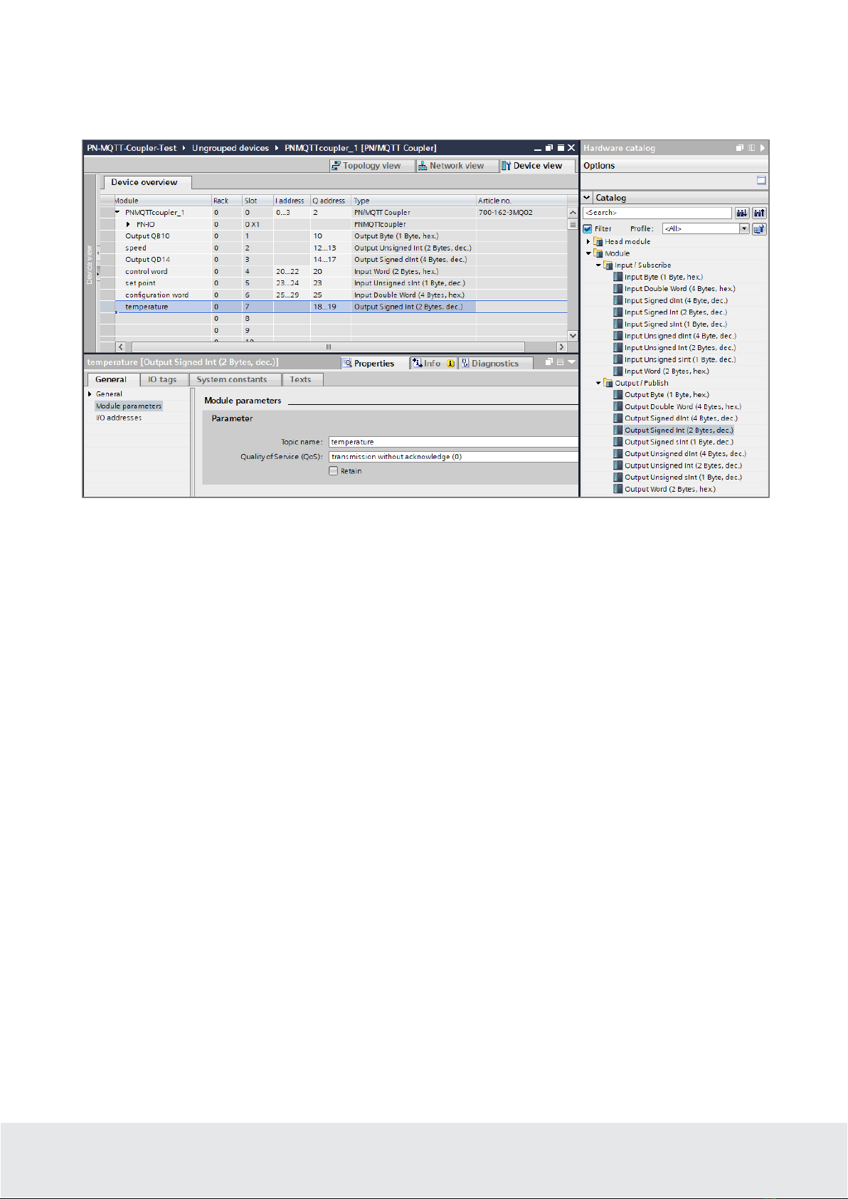
The integration into the PLC engineering tool is enabled by a GSDML file, an extra configuration
software is not necessary. The configuration of the I/O data to be exchanged is done in the Siemens
engineering tool. All settings for the MQTT connection can be done on the web page of the device.
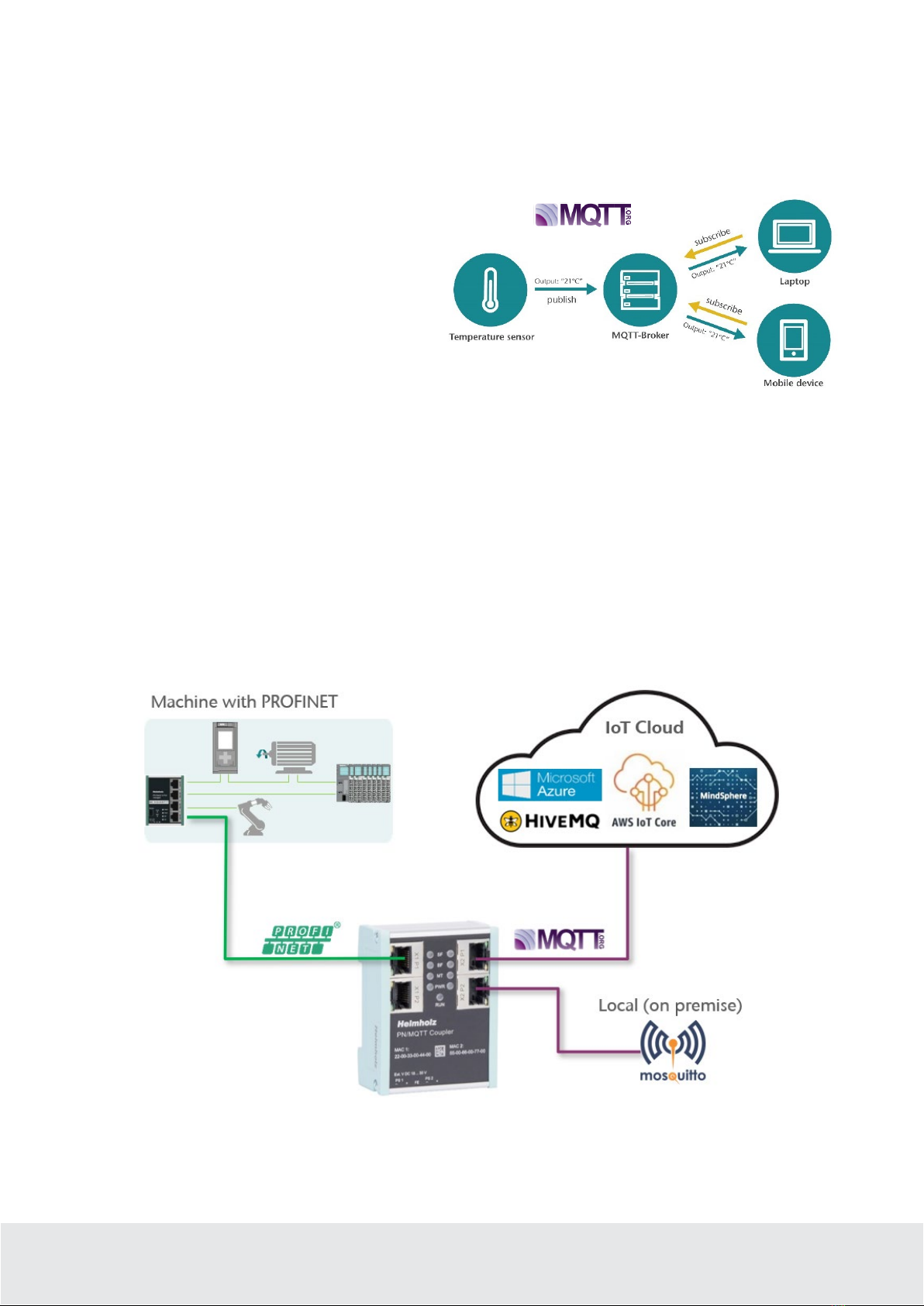
MQTT brokers can be connected both locally ("On premise") and via the Internet ("Cloud"). A local
broker can be operated, for example, with the open-source software "Mosquitto" in the company network
on a PC/server or also on a small computer, such as a Raspberry PI. Such an application is described in
this QuickStart Guide.
The PN/MQTT coupler can only establish a connection with one broker! If the data is also to be
distributed to other brokers, the connection must be established between the brokers (Multi
Broker).
In the cloud, IoT systems such as HiveMQ, Amazon IoT, Microsoft Azure or Siemens Mind-sphere (in
preparation) can be connected directly. White papers on the specific configuration settings can be
requested from Helmholz Support.
4Connection
4.1 Power supply
The PN/MQTT coupler must be supplied with DC 24 V at the wide-range input DC 18 ... 30 V via the
supplied connector plug. The power supply is redundant, at least one supply path PS 1 or PS 2 must be
connected.
The housing of the PN/MQTT Coupler is not grounded. Please connect the functional earth terminal
(FE) of the PN/MQTT Coupler properly to the reference gantry.
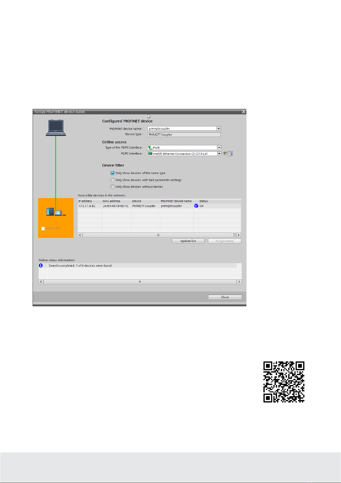
4.2 Network
The left RJ45 sockets "X1 P1" and "X1 P2" are used to connect the PROFINET network, the right RJ45
sockets "X2 P1" and "X2 P2" are used to connect the Ethernet network in which the MQTT broker is
accessible. The ports X1 P1 and X1 P2, as well as X2 P1 and X2 P2 are each internally connected to a
switch.
The interfaces X1 and X2 are logically separate networks and not physically connected. Thus a clear
separation between the machine data (PROFINET) and the MQTT data connection is possible. A network
penetration with other functions by the PN/MQTT coupler
is not possible.
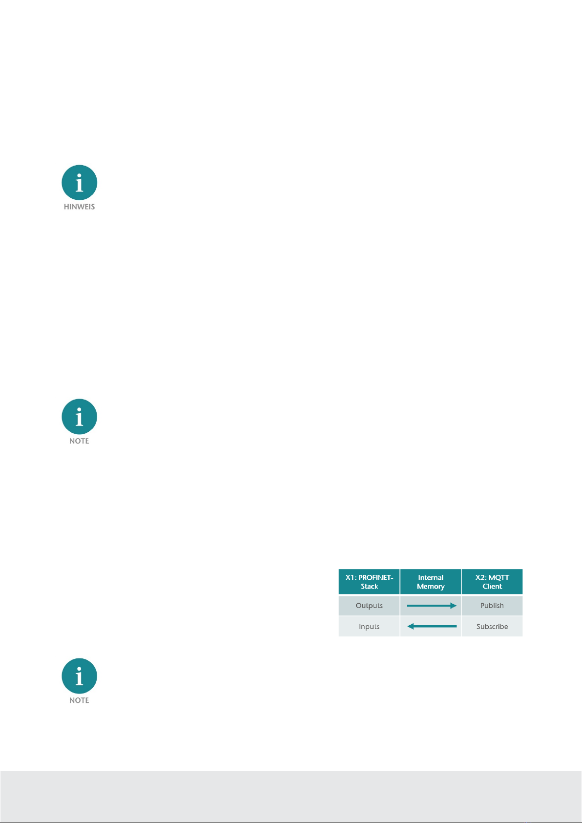
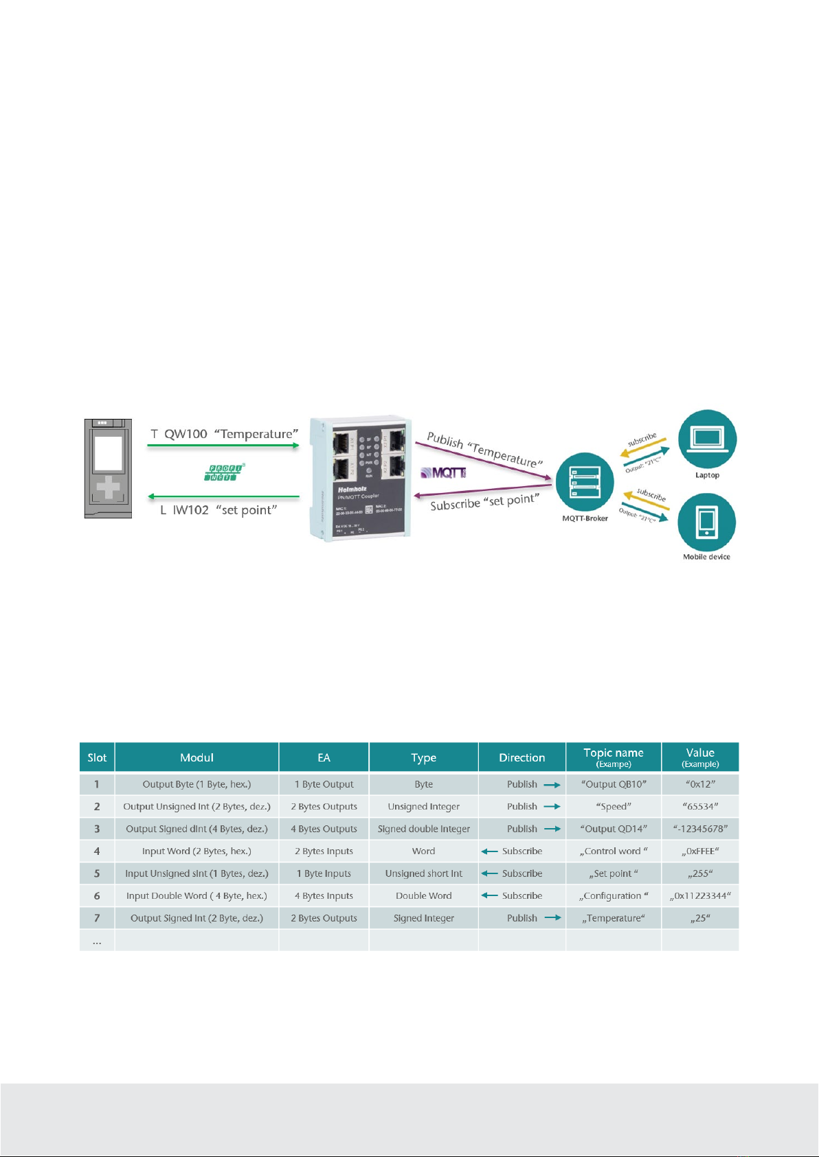
The configured values are exchanged in the PN/MQTT
coupler only as IO data between both network sides.
If the MQTT broker should be placed in the same network (subnet) as the PROFINET PLC, the
network X2 can be configured in the same subnet as the network X1.
The interface X2 then needs its own IP address and must be connected to the network X1 with an
Ethernet cable.

QuickStart Guide PN/MQTT Coupler | Version 2 | 15.02.2021 6
5Install GSDML file
Please download the GSDML file ("GSDML-V2.35-Helmholz-PN-MQTT-coupler-
____.xml") at www.helmholz.de or scan the QR code. Install the GSDML file in the
"Tools" / "Manage device description file (GSD)" menu in the TIA Portal.
The PN/MQTT Coupler can be found in the hardware catalog at
"Other field devices / PROFINET IO / Gateway / Helmholz GmbH &
Co. KG".

QuickStart Guide PN/MQTT Coupler | Version 2 | 15.02.2021 7
6Configuration in TIA Portal
Add the PN/MQTT coupler to the project and connect the coupler to the PROFINET network.
Assign a device name and check the Ethernet address for the device.
6.1 Parameterization of the PN/MQTT coupler
The parameterization of the PN/MQTT coupler is performed via the PROFINET hardware configurator
(e.g. TIA Portal). The PROFINET parameters and the I/O data to be transmitted via MQTT are defined
here. The configuration of the MQTT network connection (connection to the MQTT broker) is set via the
web page of the device.
MQTT IP-address mode (X2): Setting the IP address for the X2 network. Possible options: "DHCP",
"Static IP" or "use IP from web page setting".

QuickStart Guide PN/MQTT Coupler | Version 2 | 15.02.2021 8
Static IP address: If the address mode is set to "Static IP", the static IP address of the X2 network can be
specified here.
Static IP subnet mask: If the address mode has been set to "Static IP", the subnet mask of the X2 network
can be specified here.
Static IP gateway: If the address mode has been set to "Static IP", the gateway of the X2 network can be
specified here.
Hostname mode: "From PROFINET configuration" or "From webpage".
DHCP hostname: Name of the device
Webpage: On which network interfaces should the web page be displayed.
6.2 Operating principle of the PN/MQTT coupler
The data exchange between the PLC and the MQTT broker is organized via individual values. A value can
be 1, 2 or 4 bytes in size and is in the I/O area of the PROFINET controller. Depending on the data
direction, the value is writable to outputs (MQTT Publish) or readable from inputs (MQTT Subscribe).
Up to 100 different values can be exchanged between the PROFINET controller and the MQTT broker
(100 slots). The values can be plugged as modules into the slots of the coupler as required.
A module always represents exactly one value, which is exchanged with the broker via an MQTT topic
name. A value is usually sent via MQTT in a readable form (direct text or JSON formatted). For this
reason, there are different representation forms for each value size (1, 2, 4 bytes): hexadecimal, unsigned
decimal, signed decimal.
Configuration example:
Output modules are sent to the broker once after restarting the coupler and then after each change of the
PLC value. If PLC values are sent that change very quickly, it is possible to specify a publish interval on
the configuration web page to reduce a communication overload.

QuickStart Guide PN/MQTT Coupler | Version 2 | 15.02.2021 9
The value of the input modules is initialized with 0 after restarting the coupler and is permanently taken
over into the input area when a new value is received via MQTT. A bit additionally indicates the
reception of a value in the PLC.
For each module, the Topic name must be defined unambiguously in the module parameters. The name
can be chosen suitable to the symbolic name of the PLC value. Up to 40 characters are available.
As another parameter, the method of Quality of Service (QoS) of the topic can be specified.
Transmission without acknowledge (0): The topic is sent without an acknowledgement from the broker
(„fire-and-forget“)
Transmission with acknowledge (1): The topic is sent, and an acknowledgement ("PUBACK") is expected
from the broker. If no acknowledgement is received, the topic is sent again.
Transmission with acknowledge and confirmation (2): Provides the guarantee that a message has been
"delivered exactly once". In order to be able to keep this guarantee, MQTT uses a two-stage
acknowledgement of receipt.
Retain:This option tells the broker to save the last message or value in the broker even if the connection
to the MQTT client fails.

QuickStart Guide PN/MQTT Coupler | Version 2 | 15.02.2021 10
6.3 Assign a name to the PN/MQTT coupler
When the configuration of the PN/MQTT coupler is completed in the hardware configurator of the
engineering tool, it can be imported into the PLC.
To enable the PN/MQTT Coupler to be found by the PROFINET controller, the PROFINET device name
must be assigned to the PN/MQTT Coupler. To do this, use the "Assign device name" function, which you
can access with the right mouse button or in the Online menu if the PN/MQTT Coupler is selected.
Use the "Update list" button to search the network for PROFINET stations. With "Assign name" the
PROFINET device name can be assigned to the device.
The unique identification of the PN/MQTT coupler is guaranteed here by the MAC address of the device.
The PROFINET MAC address can be read on the front of the PN/MQTT Coupler on the left-hand side at
X1 ("MAC 1").
If the PN/MQTT coupler has received the correct PROFINET name, it is recognized and configured by the
PLC. If the configuration is correct, the PROFINET "BF" LED should be off.
To set the PROFINET name, the Helmholz IPSet Tool can also be used, which can be
downloaded free of charge from the Helmholz website.
Scan the following QR code to download the IPSet Tool:

QuickStart Guide PN/MQTT Coupler | Version 2 | 15.02.2021 11
7Configuration of MQTT connection
7.1 Access to the web page
As soon as the PN/MQTT coupler has been configured via the PROFINET PLC, the web page of the device
is accessible via the PROFINET network. If the IP address is also available on the MQTT network page
(static IP, DHCP successful), the web page is also accessible via the MQTT network. When accessing the
device for the first time, a password must be assigned for the user "admin".
If the web page of the device is not available, please check the "Web page" parameter in the
PROFINET configuration. (see chap. 6.1).

QuickStart Guide PN/MQTT Coupler | Version 2 | 15.02.2021 12
7.2 MQTT Configuration
The configuration to connect the MQTT broker can be done in the "MQTT" menu.
In the "IP Address" section, the IP address of the
right network port "X2" of the PN/MQTT Coupler is
displayed and can be set if it has not been specified
via the PROFINET configuration.
The MQTT broker is addressed via interface X2. If
the MQTT broker is located in the same network as
the PROFINET PLC, see note in chapter 4.2.
The necessary settings for connecting to a local
MQTT broker can be made on in the "MQTT Client
Settings" area.
MQTT version: The PN/MQTT Coupler supports
the MQTT standard "3.1.1" and the new standard
"V5". Since the two standards are not compatible,
the MQTT version must be set to match the broker.
ClientID: Name of the MQTT client when logging
on to a broker
Username/Password: Authentication at the broker
Broker address: IP address of the broker. The broker
must be in the same subnet as the IP address of the
coupler's X2 network.
Broker TCP Port: Port for the MQTT connection to
the broker
Keep alive: Time grid for the cyclic life message of
the coupler to the broker. If this message is missing,
the broker assumes a failure of the coupler.
Clean session: Information to the broker when establishing the connection whether old messages
should be deleted or saved.
Transport Layer Security (TLS):
The transmission between the client
and the broker can be encrypted.
Disabled: unencrypted data exchange
between client and broker
Enabled – without certificates:
Enables encryption without
authentication. This option does not require CA nor client certificate.
Enabled – broker certificate: enables encryption with broker authentication done by the client. This option
requires CA to be uploaded for broker verification, see menu “MQTT TLS”.
Enabled – mutual TLS: enables encryption with mutual broker and client authentication. With this option
CA and client certificate is required. On top of broker verification done by client, broker can also verify
client, because it sends its certificate during TLS handshake. Upload TLS-files in menu “MQTT TLS”.
Verify broker certificate (SNTP must be active): It is checked whether the broker certificate has
expired.

QuickStart Guide PN/MQTT Coupler | Version 2 | 15.02.2021 13
MQTT payload data format: The value of a topic is always sent in simple text form.
Example: -12345
Some MQTT applications expect a structured form in JSON format.
Example: {
"value": "-12345"
}
Publish interval: An MQTT message is sent automatically when the output value in the PLC changes.
If PLC values are sent that change very fast it is possible to limit the send interval. ‘0' tells the coupler to
send as fast as possible and a number greater than zero tells it not to send faster than x * 0.1 seconds.
7.3 Modul-Status
On the web page "Module status" the configured module configuration and the current IO data are
displayed. If there is a configuration error, the error is displayed in the "Diagnostic message" column.

QuickStart Guide PN/MQTT Coupler | Version 2 | 15.02.2021 14
8Status and control via the PLC
8.1 Status of PN/MQTT Coupler
The PN/MQTT Coupler provides a status (4 bytes) via the PROFINET input image:
Byte/Bit 7 6 5 4 3 2 1 0
Input
Byte 0
PROFINET
configuration
OK
0
PS 1
Voltage
available
PS 2
Voltage
available
0 0
X2 network
IP address
available
X2 network
cable
detected
Input
Byte 1 0 0 0 0 0 0 0
MQTT Broker
connection
active
Input
Byte 2
Last MQTT error code (MQTT V5)
or Connect Return/Reason-Code
Input
Byte 3 Reserved
8.2 Control of PN/MQTT Coupler
The PN/MQTT coupler can be controlled via the following control bits (1 byte) in the PROFINET output
image:
Byte/Bit 7 6 5 4 3 2 1 0
Output
Byte 0
MQTT
lock data
exchange
MQTT
Disconnect
connection
- - - - - Clear MQTT
Error Code
8.3 Subscribe Module
In addition to the input data for the actual value, the subscriber modules additionally have a status byte
and a control byte.
Status bits of Subscribe Module:
Byte/Bit 7 6 5 4 3 2 1 0
Input
Byte 0
1 = new data
received Receive counter
Control bits of Subscribe Module:
Byte/Bit 7 6 5 4 3 2 1 0
Output
Byte 0
1 = Reset data receive
bit - - - - - - -

QuickStart Guide PN/MQTT Coupler | Version 2 | 15.02.2021 15
9Technical data
Order no. 700-162-3MQ02
Article designation PN/MQTT Coupler
PROFINET interface (X1)
Connection 2x RJ45, integrated switch
Protocol PROFINET IO Device as defined in IEC 61158-6-10
Transmission rate 100 Mbit/s full duplex
I/O image size max. 1024 Byte of input/output data
Number of configurable slots 100
Features
PROFINET Conformance Class B (in preparation), media redundancy
(MRP-Client), automatic addressing, Topology detection (LLDP, DCP),
diagnosis alarms
MQTT interface (X2)
Connection 2x RJ45, integrated switch
Protocol
Transmission rate 10/100 Mbit/s, full-/half duplex
Status indicator 9 LEDs function status, 8 LEDs Ethernet-status
Voltage supply DC 24 V (18 - 28 V DC)
Current draw max. 210mA
Power dissipation max. 5 W
Dimensions (D x W x H) 35 x 58 x 72 mm
Weight approx. 135 g
Certifications CE, PROFINET Conformance Class B (in preparation)
Protection rating IP 20
Relative humidity 95% non-condensing
Mounting position any
Ambient temperature 0° C to 60° C
Transport and storage temperature -20° C to 80° C

QuickStart Guide PN/MQTT Coupler | Version 2 | 15.02.2021 16
10 LED status information
X1 PROFINET (left side) X2 MQTT network (right side)
SF (red)
Off Configuration correct Configuration correct
On There is no configuration, the configuration is faulty
or MQTT broker connection is not possible.
PROFINET side not configured or failed
Flashing PROFINET function "LED flashing" for finding the
device is executed
-
BF (red)
Off The device is configured Network configuration is valid and MQTT broker
connection is active
On
The device has no configuration, the PROFINET
device name is incorrect, or there is no connection
with the PROFINET controller
Network configuration is valid, but no MQTT broker
connection exists
Flashing PROFINET function "LED flashing" for finding the
device is executed
No connection possible due to faulty or non-existent
network configuration
MT (yellow)
Flashing A firmware update is being carried out A firmware update is being carried out
Flashing with
SF and BF
PROFINET function “LED flashing” for finding the
device is being carried out
PWR (green)
On PS1 Power supply present PS1 Power supply present
RUN (green)
Off Firmware or device defective. Please contact Support
On The device is ready to operate
RJ45 LEDs X1 P1/P2 und X2 P1/P2
Green (Link) Connected
Orange (Act) Data transfer at the port active
The contents of this Quick Start Guide have been checked by us so as to ensure that they match the
hardware and software described.
However, we assume no liability for any existing differences, as these cannot be fully ruled out. The
information in this Quick Start Guide is, however, updated on a regular basis. When using your
purchased products, please make sure to use the latest version of this Quick Start Guide, which can be viewed and
downloaded on the Internet from www.helmholz.de.
Our products contain open source software, among others. This software is subject to the respectively relevant
license conditions. We can send you the corresponding license conditions, including a copy of the complete license
text together with the product. They are also provided in our download area of the respective products under
www.helmholz.de. We also offer to send you or any third party the complete corresponding source text of the
respective open source software for an at-cost fee of 10.00 Euro as a DVD upon request. This offer is valid for a
period of three years, starting from the date of product delivery.
Our customers are important to us, we are happy to receive suggestions and ideas for improvement. If you have any
questions regarding the use of the product, please contact Helmholz Support by phone or send an e-mail to
support@helmholz.de.
* Simatic and STEP 7 are registered trademarks of Siemens AG.
* Windows is a registered trademark of Microsoft Corporation.
This manual suits for next models
1
Table of contents
Other Helmholz Adapter manuals

Helmholz
Helmholz PN MQTT User manual

Helmholz
Helmholz 700-159-3MB01 User manual

Helmholz
Helmholz TB20 User manual

Helmholz
Helmholz SSW7-RK512/RS422 User manual

Helmholz
Helmholz 700-158-3DP02 User manual

Helmholz
Helmholz SSW7-USB User manual

Helmholz
Helmholz SSW7-RK512 User manual

Helmholz
Helmholz 700-159-3MB02 User manual
Popular Adapter manuals by other brands

NetComm
NetComm V100LS quick start guide

NETGEAR
NETGEAR Wg111v2 - Usb Wifi Card Includes Driver Cd user manual

SnowDogg
SnowDogg 16071120 installation instructions

BeiJer
BeiJer GN-9289 user manual

Azio
Azio AES100A Quick installation guide

Adaptec
Adaptec 131CA - AAA RAID Controller Installation and hardware guide