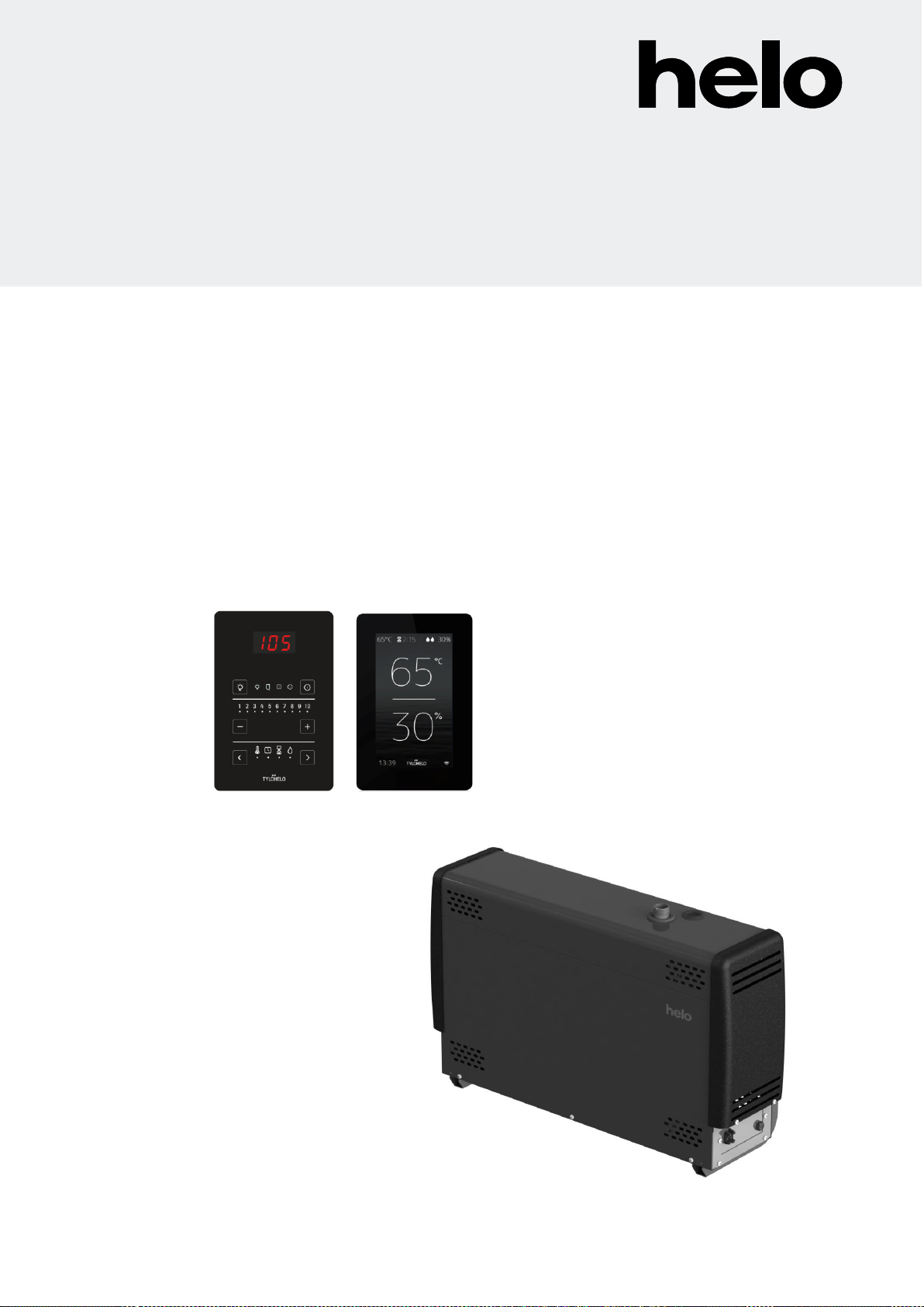
Helo Pure Operation manual

STEAM GENERATOR
Helo Steam (1317 - … - 171) 3,4 kW –7,7 kW
CONTROL CENTRE Pure Elite
314 SHS 111-3 B
Instructions for Use and Installation Helo Steam
REWARD YOURSELF

Contents
Specifications 2
Easy maintenance 3
Accessories 3
General 3
Warnings 3
Installation principle 4
Overheating protector 5
Main switch 5
Ventilation 5
Descaling 6
Cleaning the steam room 6
Steam generator couplings 7
Water and steam pipe connections 8
Electrical connections 9
Remote control 9
Circuit board RJ connectors 9
Switch diagram 10
Heating elements 11
Steam generator resistors 11
Selecting the steam generator output for the steam room 11
Troubleshooting 12
ROHS 14
Specifications
Operating voltage 230V –240V 1N~ / 2~
230V 3~
400V –415V 3N~
Output options 3.4 / 4.7 / 6.0 / 7.7 / 9.5 / 12.0 / 14.0 kW
Steam generator dimensions 520 x 380 x 160 mm
Parallel coupling Max 5 steam generators.
Enclosure class IP 20
Installation Floor / wall
Water tank material Aisi 304, stainless steel
Water tank pipes Aisi 304, stainless acid-proof steel
Weight when empty about 12 kg
Electric water level adjustment
Electric overfill protector
Limescale-repelling self-cleaning electrodes
Overheating protector
Safety relief valve
Digital control panel Pure or Elite
2
Instructions for Use and Installation Helo Steam

Easy maintenance
Replaceable heating elements (3 pcs)
The steam generator has an overheating protector equipped with a reset button
The fill cap for limescale remover (citric acid) has been placed on a steam pipe of the steam generator cover (see
image on page 6).
Components (circuit board, heating elements, surface sensor) are easy to replace.
Accessories
- Essence pump, (Essence pump kit 0038130)
- Essence pump canister 20 l (0038132)
- Automatic flush and rinse cycle. Automatic drain valve 4310130
- Steam nozzles (3.4 –6.0 kW 1 piece, 7.7 –9.5 kW 2 pcs, (7819604)
- Remote control on/off push button (External switch 90908047)
General
The Steam generators are only intended for use in heating spa facilities. Using steam generators in areas other than
steam rooms can damage the building's structure.
The manufacturer is not responsible for damages caused if the unit has been used incorrectly or in a manner for
which the unit was not designed.
Water and steam pipe connections must be made prior to connecting the unit into the mains.
Due care and attention must be taken when making the connections. Proper sealing must be ensured for all
extensions. A good extension must at least have taped-over twist connections, but it is recommended that
connections are soldered.
NOTE: Controlling the lights in the steam room with the circuit board is is only possible with resistive loads
(incandescent light bulbs). The circuit board relay cannot withstand capacitive loads (switched-mode power supply
units). If the lighting fixtures in the sauna have transformers, for example LED or halogen lamps, the steam generator
circuit board's relay control must be fitted with a separate relay or contactor for controlling the lights.
Operation of the steam generator controls
Refer to the specific control panel operating manual for the instructions.
Warnings
- This appliance is not intended for use by persons (including children over the age of 8) with reduced physical,
sensory or mental capabilities, or lack of experience and knowledge, unless they have been instructed about
the safe use of the appliance and the risks involved. Children must not be allowed to play with the appliance or
to clean and service it without supervision. (7.12 EN 60335-1:2012)
- The steam generator produces hot water vapour (100 °C) while in use.
- Disconnect the appliance from the electrical supply before servicing and cleaning it.
- Water connection pressure 0.2–1 MPa (2–10 bar)
Warning: Hot water vapour
3
Instructions for Use and Installation Helo Steam

Testing the water before using the steam generator.
The water test kit supplied with the steam generator includes test slips which are used to determine water hardness
as follows:
Dip the test slip in water for about 1 second, take it out and shake off the excess water. After a minute, compare the
colour code appearing on the test slip with the code key in the packet.
Test result: °f = French degrees, °dH = German degrees
< 5° f ( 3° dH ) Very soft water.
> 7° f ( > 4° dH ) Soft water. Installing the descaling device is recommended
> 12° f ( > 7° dH ) Medium-hard water. Install descaling device. Retest the water hardness.
> 25° f ( > 14° dH ) Hard water. Install descaling device. Retest the water hardness.
> 37° f ( > 21° dH ) Very hard water. Install descaling device. Retest the water hardness.
See page 6 for steam generator's operation time in hours before descaling is required.
The steam generator must be placed away from water and moisture (dry room). The room must be airy as the unit
also produces heat. The temperature of the space where the steam generator is located must not exceed 35 °C. We
recommend leaving at least 300 mm of free space to the sides and above the steam generation unit. Adequate space
for maintenance should also be planned for when placing the unit. There should be a drain nearby for draining the
tank.
The steam generator can be installed as a freestanding unit or installed on the wall using wall fittings. When using
wall fittings, ensure you use appropriate fittings and screws for the type of construction material of your walls. The
steam generator weighs about 18 kg when filled with water.
When the automatic drain valve is used, it is recommended you use wall installation to ensure a suitable angle for
draining water.
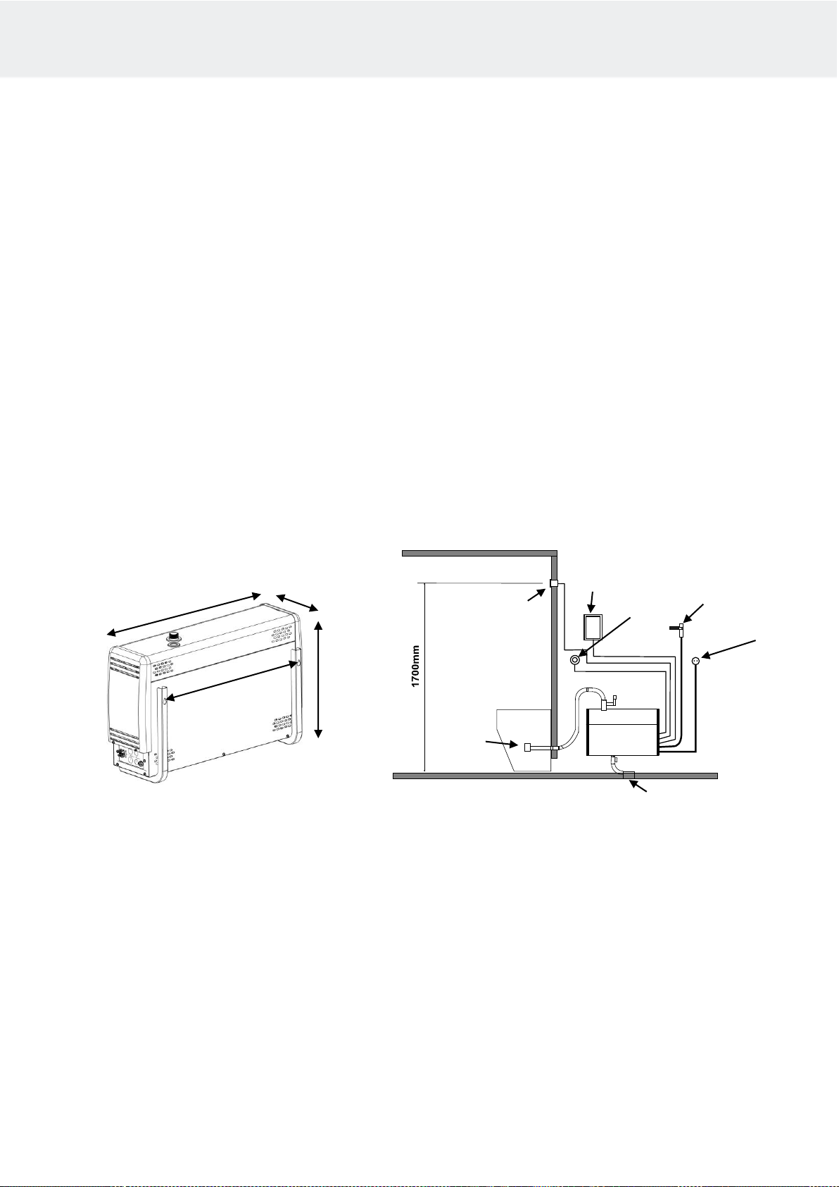
Principle diagram for installation
Installing the control panel Steam generator wall mounting
The control panel of the Helo Steam unit is installed outside the steam room.
The cable of the control panel can be extended with a similar cable.
Steam nozzle / nozzles are fitted approximately 200–400 mm from the floor underneath a bench or a seat, or onto
the wall so that the hot steam cannot burn anyone's feet. The steam nozzles are aimed towards the floor. When the
nozzles are installed, you must ensure that you place them somewhere where nobody can accidentally touch them.
The steam temperature is +100 °C and it can cause injuries on contact.
If children or people with impaired reflexes use the steam room, the steam nozzle must be fitted with a protector that
prevents people from getting into the hot steam shower.
4
Instructions for Use and Installation Helo Steam
636 mm
380 mm
523 mm
164 mm
Steam room
On/Off
Push button
Sensor
OLET 30
Control panel
Water connection
Electrical connection
Flushing
Steam nozzle

The Sensor OLET 22 should be fitted about 1700 mm above the floor, ideally on the wall opposite the door. We
recommend sealing the sensor installation hole with appropriate sealing material, so that moisture cannot enter the
structures.
The steam room thermometer must installed at the height that gives the same reading as that shown on the control
panel.
The On/Off push button (accessories, External switch) can be used for starting and stopping of the steam
generator remotely. the push button is installed outside the steam room.. For more information about the control
panel and reception couplings, please refer to the user manual and the switch diagram.
Overheating protector
The steam generator is equipped with an overheating protector. If the protector has tripped, find the root cause with
the troubleshooting guide in the instruction manual. The overheating protector is reset by pushing a button.
NOTE: The overheating protector is located under the upper lid of the steam generator. Only a qualified electrician is
allowed to do this.
Main switch
There is a main switch at the bottom of the end of the steam generator, which should only be used when the steam
room will not be used for a long period of time.
The steam generator's automatic flushing and rinsing function will stop if the power is switched off. (Accessory,
Automatic drain valve)
Ventilation
There is usually no need to ensure ventilation of steam saunas that are used for less than two hours. Steam rooms
that are used for more than two hours at a time, on the other hand, do need ventilation for functional and hygienic
reasons. The recommended rate of ventilation is is 10–20 m³ per person per hour.
If there is an empty space above the ceiling of the steam room, it must not be completely sealed off. Make at least
one ventilation hole (100 mm x 100 mm) leading to the empty space, on the same wall as the door.
The supply air valve may be a hole in the bottom part of the wall with the door or a gap under the door.
The exhaust valve is place in the ceiling or on a wall near the ceiling as far from the supply air valve as possible,
however not above the door or the seats. The exhaust valve is connected to an air conditioning channel going
outside
Forced ventilation. If natural ventilation is not adequate (e.g. negative pressure in the room where the fresh air is
taken from), the steam room must be equipped with forced ventilation. Its output must be equivalent to 10–20 m³ of
ventilation per person per hour.
5
Instructions for Use and Installation Helo Steam
Descaling
The tank must be flushed after every use.
To prolong its service life and to reduce the need for manual decalcification we recommend that steam generators
are connected to a water softening filter, which removes the calcium. This is especially important if the water
hardness exceeds 7° dH (German hardness).
The water softener must not generate foam or produce harmful chemicals, which may give erroneous view of the
water level in the tank and cause the temperature switch to trip. (Heating elements will break down after some time.)
Manual descaling should be performed according to the chart below.
In normal private use, the need for descaling is minimal if the water is not particularly hard. However, the steam
generator must be descaled at least once a year. This removes the limescale from the tank walls and heating
elements.
Warning: The inlet pipe nut may be hot.
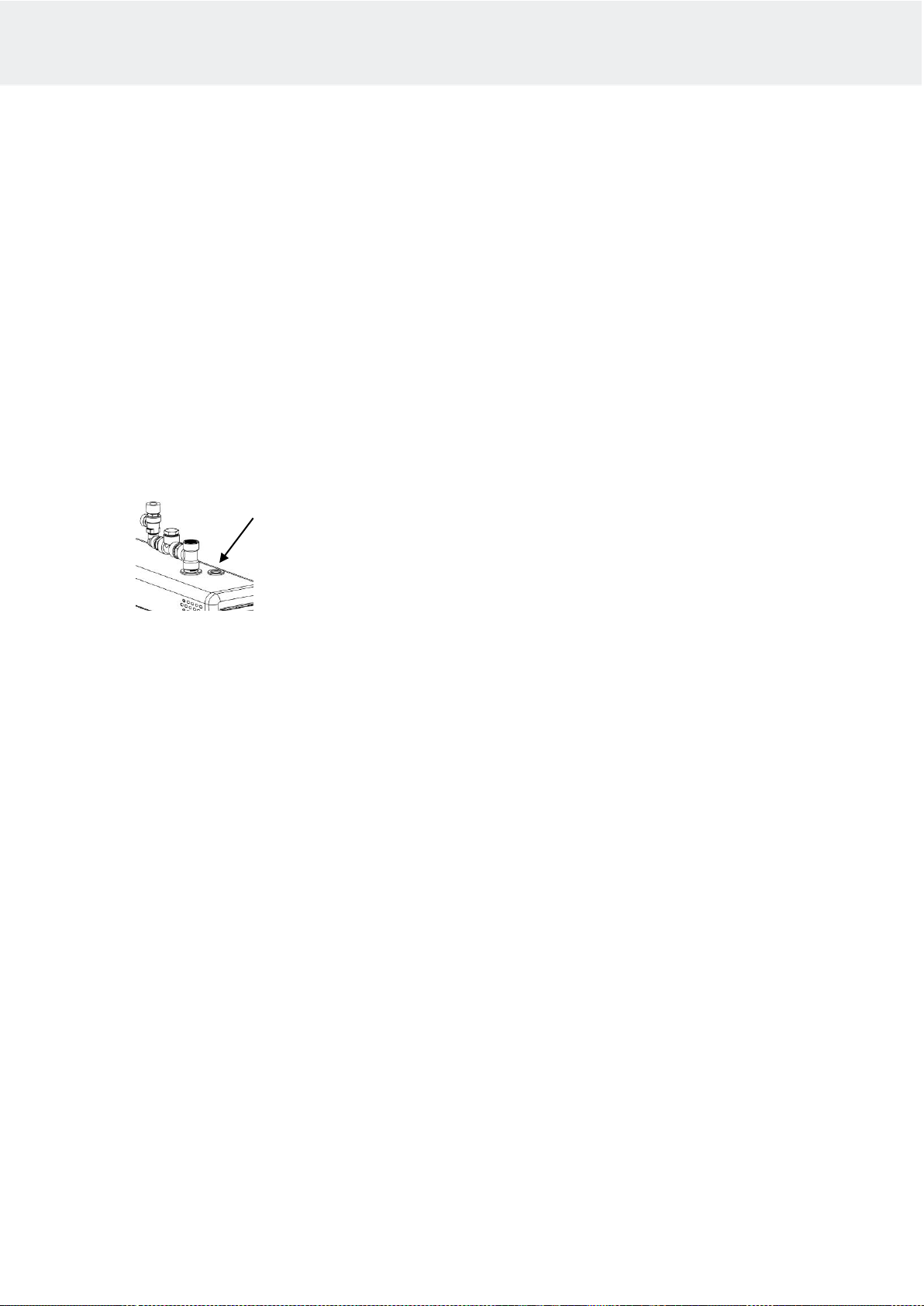
Steam generator descaling
•Start the steam generator and let it run until the water in the tank boils.
•Stop the steam generator and wait for about 5 minutes.
•Remove the connecting piece's lid nut at the top of the steam generator.
WARNING: The nut on the lid might be hot –risk of burning.
•Pour the descaling agent (e.g. citric acid) into the tank via the connecting piece using a funnel.
•Attach the lid nut to the connecting piece and let the agent work abot 1 hour
•Empty and rinse the tank until it is clean. The steam generator is now ready for use again.
Citric acid is an odourless and harmless descaling agent and it does not harm the steam generator's components.
If any other type of descaling agent is used, you must not bathe during the descaling procedure.
As can be seen from the adjoining chart, the need for manual descaling depends on water quality, steam generator
output and operation time.
Operation time in hours before descaling is required. A water softener must be used in public facilities
to reduce the need for manual descaling. . An electric drain valve can also be installed (Automatic drain
valve, sold separately).
Hours of operation, different hardnesses
Steam generator
output kW
Amount of descal-
ing agent. Citric
acid (1 bag 50g)
Softened water
0.01 –1° dH
Soft water
1–3° dH
Medium-hard
water
4–7° dH
Hard water
8–14° dH
3.4 kW
2 bags
7000
2300
900
350
4.5 kW
2 bags
3800
1300
500
190
6.0 kW
2 bags
2600
900
300
130
7.7 kW
2 bags
1700
600
200
90
Cleaning the steam room
Rinse the seats and the floor with warm water after every use (do not use a pressure washer). Clean the seats
regularly with mild detergent Use ethyl alcohol or dilutine. Never use abrasives, strongly alkaline detergents or
solvents to clean the steam room seats and walls. Contact the manufacturer if necessary.
It is important to clean the floor carefully all the way to the corners. Use hot water, a brush and floor detergent that
removes dirt and grease.
6
Instructions for Use and Installation Helo Steam

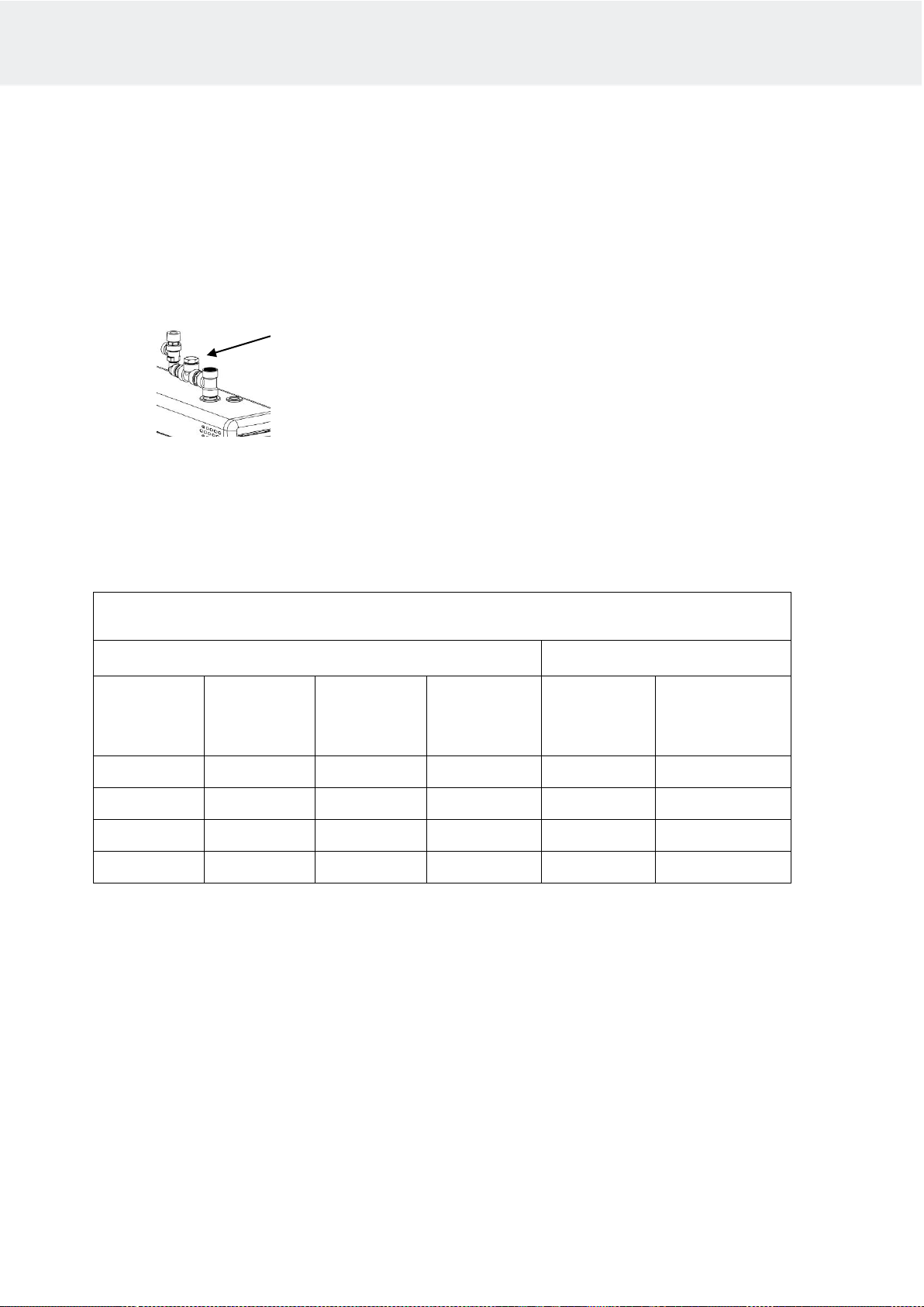
Steam generator couplings
Safety valve installation
The safety relief valve is installed on the cover's steam hose with the supplied components.
As a minimum, seal the threads using thread seal tape.
A separate downpipe directly to a drain or to the floor is installed on the safety valve. NOTE: The safety valve's
downpipe must not be connected to the steam generator's draining pipe or the steam pipe. Use the sealing tape
provided or similar sealing on the threads.
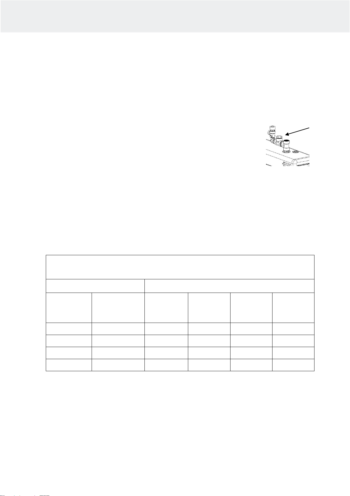
Image. Installation of the safety relief valve and the automatic drain (Accessory, Automatic drain valve). See the circuit
diagram for the coupling.
7
Instructions for Use and Installation Helo Steam
Drainage for manual
or electronic ¾” valve.
Safety relief valve installed in
the steam pipe
Steam pipe ¾”
Maintenance fill cap
for e.g. citric acid
Connectors for
accessories
Water filler valve ¾”
Main switch
Connectors for the control
panel and temperature
sensor
Connector for the
electric supply
Fuse T3,15AH
Water and steam pipe connections
Connect the flexible water connection tube in the packaging to the water connection in the installation panel of the
unit and to the cold water piping of the building. The water pressure must be at least 0.2 Pa (2 bar) and at most
1 MPa (10 bar). The water supply pipe must have a manual stop valve for stopping water supply to the unit, if the unit
is not used for a prolonged period.
Installation must follow the local regulations
We recommended at least 18x16mm (steam generator size 3.4 kW-9.5 kW) and 22x20mm (steam generator size
12.0 kW- 16 kW) copper pipe or a silicone tube of similar size when connecting the steam pipe. The steam pipe
diameter must be the same for the whole length.
The steam pipe must be tilted upwards or downwards from the steam generator to the steam room, there MUST NOT
be any water seals or water pockets. The condensation water forming in the steam pipe must be allowed to drain
freely to the steam room or back to the steam generator. If an essence pump is connected to the steam generator,
the pipe must ALWAYS drain away from the steam generator so that the chemicals cannot get into the tank.
Recommended maximum length for the steam pipe is 5 m.
We recommend that you always use additional insulation for the steam pipe, for both safety reasons and to prevent
water condensation in the pipe.
Clearance from an uninsulated steam pipe to flammable material such as wood must be at least 10 mm.
WARNING: Hot steam can cause burn injuries.
The electromagnetic valve for draining the steam generator’s tank is fitted into the draining pipe. Alternatively you
may use a manual draining valve. Connect the downpipe (copper pipe with a minimum diameter of 16 mm) to the
downpipe of the steam generator. The downpipe is led to the nearest drain outside the steam room. The temperature
of the discharge water is 90–95 °C.
IMPORTANT! No stoppers (valves, taps, etc.) may be fitted on the downpipe.
Regardless of where the downpipe leads, it must descend all the way from the steam generator to the drain. To
ensure adequate descent, you may have to place the steam generator on a wall mount or on a stand.
The steamer generator’s tank should be drained after each use. This will extend the unit’s life and reduces
limescale build-up.
The product’s warranty will be void if the steam generator has been incorrectly installed or it has been used
in a manner other than that described in the user manual.
The warranty also expressly excludes operational faults if they are caused by hard water i.e. water with high
levels of calcium, or otherwise impure water.
The steam generator must be maintained as described in the user manual.
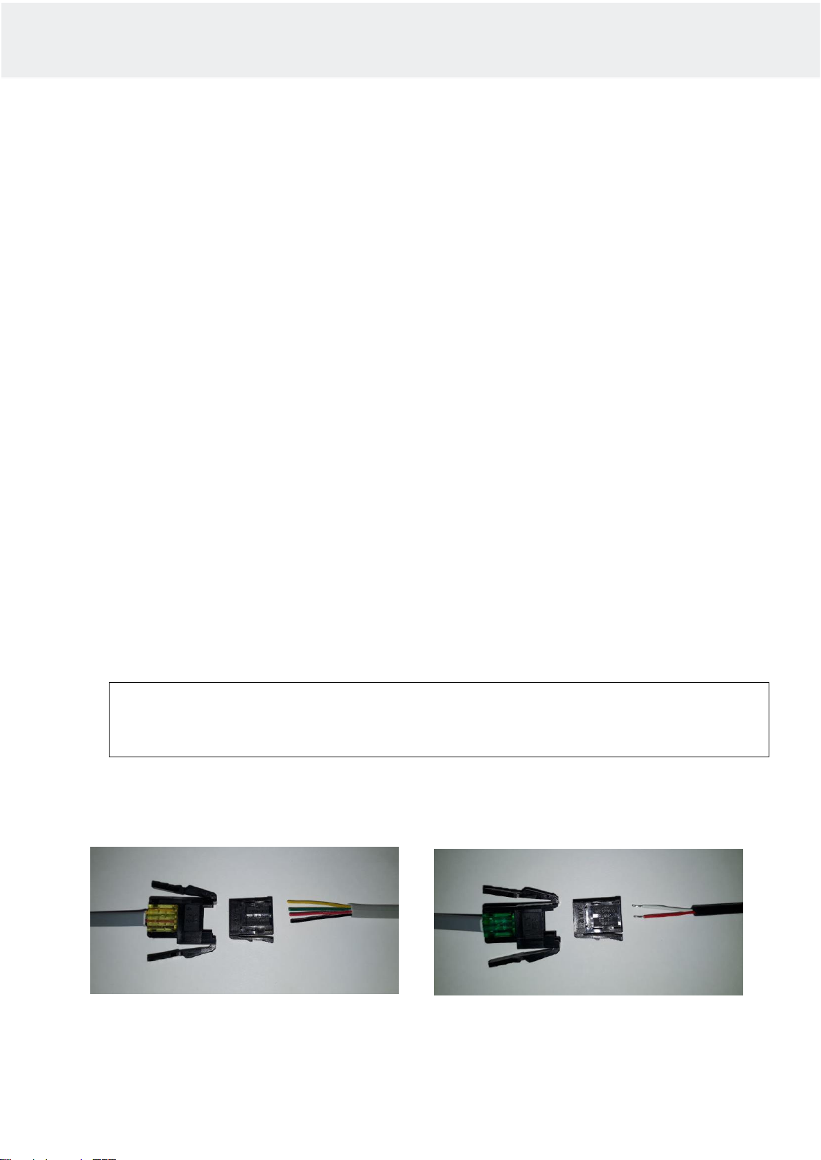
Connecting the control panel and temperature sensor cables
8
Instructions for Use and Installation Helo Steam
Connecting the temperature sensor cable
Connect the cable to connectors 2 and 3.
1 = Remains empty
2 = Red
3 = White
Connecting the control panel cable
1 = Black
2 = Red
3 = Green
4 = Yellow
4
1
3
2

Electrical connections
The sauna heater must be connected to the mains by a qualified electrician and in compliance with current
regulations.
The steam generator should be connected with a semi-permanent connection. Use H07RN-F (60245 IEC 66) cables
or a corresponding type.
NOTE: The electric supply must be fitted with a safety switch before the steam generator so that electricity
can be switched off from all poles.
Output
kW
Connection cable
H07RN-F/60245
IEC 66
mm²
400 –415V 3N~
Fuse
A
Connection
cable H07RN-
F/60245 IEC 66
mm²
230V 3~
Fuse
A
Connection cable
H07RN-F/60245 IEC
66
mm²
230–240V 1N~/ 2~
Fuse
A
3.4
5 x 1.5
3 x 10
4 x 1.5
3 x 10
3 x 2.5
16
4.7
5 x 1.5
3 x 10
4 x 2.5
3 x 16
3 x 6
25
6.0
5 x 1.5
3 x 10
4 x 2.5
3 x 16
3 x 6
25
7.7
5 x 2.5
3 x 16
4 x 6
3 x 25
3 x 10
35
Remote control
The steam generator can be controlled remotely by connecting an on/off push button to connectors 3 and 4 of the
RJ10 circuit board. The recommended cable size is AWG 24 or 26. The maximum length of an AWG 24 cable is 50
m when using a Elite controller, and 200 m when using a Pure controller.
The maximum length of an AWG 26 cable is 30 m when using a Elite controller, and 130 m when using a Pure
controller.
Circuit board RJ 10 connectors
NOTE: Incorrect connections may break a circuit board.
Additional sensor (NTC)
Remote control switch (Ext switch)
Door switch
Pin 1
Pin 1
Pin 1
Pin 2
NTC 10
kOhm
3.3 V
Pin 2
Pin 2
Alarm LED
GND
Pin 3
NTC 10
kOhm
CPU
Pin 3
To switch
GND
Pin 3
Door
switch
GND
Pin 4
Pin 4
To switch
12 VDC
Pin 4
Door
switch
12 VDC
Sensor (Sec/NTC)
4 units of RS 485
Additional relay board (Add-on)
Pin 1
End stop
GND
Pin 1
Serial
traffic
A
RJ45 cable from a relay board to
an additional relay board.
Pin 2
NTC 10
kOhm
3.3 V
Pin 2
Serial
traffic
B
Pin 3
NTC 10
kOhm
CPU
Pin 3
Power
supply
12 VDC
Pin 4
End stop
10V
Pin 4
Power
supply
GND
Pin layout of a RJ10 circuit board connector
Pin layout of a RJ10
connector
9
Instructions for Use and Installation Helo Steam
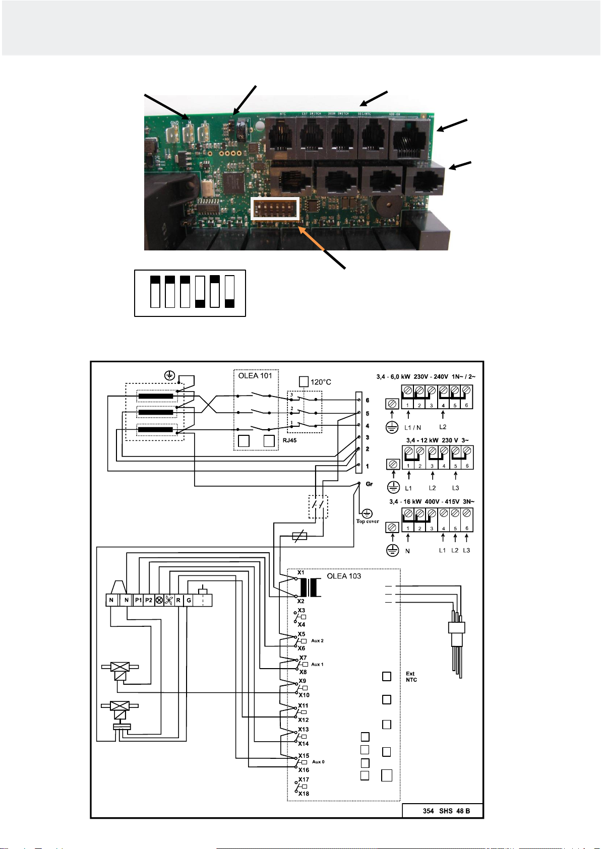
Switch diagram
DIP switch positions for
steam generators with a
manual draining valve.
RJ45 for additional
relay board
(4 pcs RJ10)
RS 485
control panel con-
nectors
DIP switches
RJ10 connectors
Surface sensor
connectors
NTC connector for
water tank sensor
ON
OFF
10
Instructions for Use and Installation Helo Steam
Control panel
X19
Contacto
P3
P2
P1
T
F1 A3,15 H
X20 X21X22
X23X24 X25X26
X27
X28 X29X30
White
Black
Red
1
2
3
On /Off
Black Red Green
Main
switch
Water valve
filling
230 V AC
Surface
sensor
Water valve
flush
230 V AC
Ground GND
Lower limit M
Upper limit H
On/Off push button
Remote control
Door switch
Sensor OLET 22
RJ45
Light
ON
OFF 1 2 3 4 5 6

NOTE: Controlling the lights in the steam room with the circuit board is is only possible with resistive loads
(incandescent light bulbs). The circuit board relay cannot withstand capacitive loads (switched-mode power supply
units). If the lighting fixtures in the sauna have transformers, for example LED or halogen lamps, the steam generator
circuit board's relay control must be fitted with a separate relay or contactor for controlling the lights.
Steam generator resistors
Selecting the steam generator output for the steam room
You can estimate the power requirement using the formula below.
Volume (m3) x K1 x K2 = Power requirement (kw)
Mechanical ventilation K1 = 0.75
No ventilation K1 = 0.52
Acrylic wall K2 = 1.00
Light wall board + tile K2 = 1.25
Heavy wall: stone, concrete + tile K2 = 1.50
Very heavy wall: stone, concrete + tile K2 = 2.00
In heavy-built steam rooms, we recommended using e.g. an electric heating cable for warming the seats, walls and
floors.
Output
Light structure,
acrylic, tem-
pered glass
Light board
wall
+ tile
Heavy
wall,
concrete,
stone
Steam
kg / h
kW
No ventilation
Air condi-
tioned
No ventila-
tion
Air condi-
tioned
No ventila-
tion
Air condi-
tioned
3.4
2–7 m³
2–6 m³
2–6 m³
2–5 m³
2–5 m³
2–4 m³
5
4.7
3–8 m³
3–7 m³
3–7 m³
2–6 m³
2–6 m³
2–5 m³
6
6.0
4–13 m³
4–9 m³
4–8 m³
3–7 m³
3–7 m³
3–6 m³
8
7.7
6–15 m³
6–11 m³
6–10 m³
5–9 m³
5–9 m³
4–8 m³
10
Table for selecting a steam generator based on the steam room volume and wall materials.
Output
kW
Resistor 230V
1 2 3
3.4
1150W / SEPD 97
1150W / SEPD 97
1150W / SEPD 97
4.7
1567W / SEPD 98
1567W / SEPD 98
1567W / SEPD 98
6.0
2000W / SEPD 99
2000W / SEPD 99
2000W / SEPD 99
7.7
2567W / SEPD 100
2567W / SEPD 100
2567W / SEPD 100
12
Instructions for Use and Installation Helo Steam

Troubleshooting
WARNING! The steam generator may have several electric circuits.
Make sure that the device is completely de-energised before carrying out any work.
Checks and troubleshooting.
In case of malfunction check that:
•the control panel and the steam generator are installed according to the connection diagrams
•the steam generator is installed properly according to this instruction manual
•the downpipe has adequate descent towards the drain
•the dirt filter is clean. The filter is in the incoming water connector. Open the pipe connector for cleaning, remove the
filter and remove all the limescale and dirt from it.
•there are no water pockets in the steam pipe or in the outgoing air conditioning pipe.
•There are no sharp bends in the steam pipe (bend radius must be at least 50 mm).
•If there is a tap on the incoming water pipe to the steam generator, this is open.
•the steam room's structure and air conditioning match the installation and building instruction.
Troubleshooting chart
Possible causes and suggestions for fixes
Warming up takes abnormally long.
Cause: Inadequate power output of the steam generator. See output chart.
Action: Replace with more powerful steam generator.
Cause: Excessive ventilation of the steam room.
Action: Reduce ventilation so that it is 10-20 m³ per person per hour.
Cause: Blown fuse in the switchboard.
Action: Replace the fuse.
Action: Replace the heating element
Cause: The sensor is too close to the steam shower.
Action: Move the sensor to another location or redirect the steam shower.
The steam room does not warm up or there is no steam.
Cause: Blown fuse in the switchboard.
Action: Replace the fuse.
Cause: No water is coming to the steam generator.
Action: Open the incoming water tap.
Cause: The control panel is not set up right.
Action: Check the time and temperature settings.
Cause: The dirt filter is blocked.
Action: Remove the dirt filter from the incoming water connector and clean it.
Cause: The electromagnetic valve for the incoming water is stuck.
Action: Remove the electromagnetic valve and clean it.
Cause: Too much limescale has accumulated in the steam generator's water tank. See test 1.
Action: Clean the water tank and surface sensor's pins and replace the heating elements, if necessary.
Cause: The steam generator is connected for an incorrect voltage (V).
Action: Check the voltage and the steam generator's connections. See the Connection diagram.
Cause: The overheating protector has tripped. See test 4.
Action: Check and fix possible faults in the steam pipe, e.g. blocks caused by several sharp bends, water pockets or
significantly reduced inner diameter of the pipe. It is also possible that the tank has been filled with limescale deposits
or impurities. See the previous entry.
Cause: Fault in the circuit board, control panel or electromagnetic valve.
Action: Replace the faulty part.
13
Instructions for Use and Installation Helo Steam

Warm water comes out of the steam nozzle, there is little or no steam in the steam room.
Cause: The electromagnetic valve for the incoming water is stuck open because of dirt or an electrical fault.
See test 3.
Action: Remove the electromagnetic valve and clean it. Fix the electrical fault.
Cause: The electromagnetic valve is broken.
Action: Replace the electromagnetic valve.
Cause: Fault in the circuit board.
Action: Replace the circuit board.
Warm water comes out of the steam nozzles in pulses or as a weak continuous stream with steam.
Cause: Small water pocket in the steam pipe.
Action: Remove the water pocket.
Cause: Too much of the steam pipe is uninsulated.
Action: Insulate the steam pipe.
Warm water continuously comes out of the steam generator's downpipe.
Cause: The automatic electromagnetic flushing valve is stuck open.
Action: Turn off the steam generator. Try again after 80 minutes. If the fault remains, remove the automatic
electromagnetic flushing valve and clean it.
Banging noise from the water pipes when the electromagnetic valve opens or closes.
Cause: Inadequate connection in the water pipe coming into the steam generator.
Action: Mount the water pipe securely on the wall.
Cause: Recoil effect in the incoming water pipe.
Action: Install about 1 metre of pressure-proof reinforced rubber hose into the steam generator end of the water pipe.
The safety valve opens or the overheating protector trips.
Cause: Steam pipe is blocked. See test 4.
Action: Remove the block.
Cause: The inner diameter of the steam pipe has significantly decreased. See test 4.
Action: Replace the pipe or the connection where the inner diameter is reduced (minimum inner diameter is 16mm).
Cause: Several sharp bends in the steam pipe. See test 4.
Action: Make the bends less sharp.
Cause: There is a large water pocket in the steam pipe. See test 4.
: Install the steam pipe so that water pockets do not form.
Steam generation is irregular from the beginning.
Cause: The sensor is badly placed. See test 2.
Action: Move the sensor or redirect the steam shower.
Cause: Limescale or other impurities in the dirt filter.
Action: Remove the dirt filter and clean it.
13
Instructions for Use and Installation Helo Steam
TEST 1.
Checking limescale deposits in the water tank.
Open the steam generator's uppermost lock nut. Lower a torch bulb that is connected to a battery with wires into the
opening use it to light up the interior of the water tank. If there is a layer of limescale thicker than 3 cm on the bottom,
the steam generator has not been serviced and the limescale has not been removed according to the instructions.
It is also possible that the flushing and rinsing automation is not working. Check that the steam generator power has
not been switched off after bathing using any switches fitted in the supply line. You should only switch the power off
from this switch 80 minutes after the control panel has switched the power off.
Check the automatic flushing function by placing a container with a volume of about 12 litres under the downpipe.
Start the steam generator for about 15 minutes. Switch off the steam generator exactly the same way you normally
do after bathing. Wait at least 80 minutes and check if the vessel is filled with water. If it is not filled, there is a
problem with the steam generator's electric connections or the power supply has been switched off using a switch on
the wire leading from the switchboard directly to the steam generator. It is also possible that the exhaust valve is
blocked or the circuit board is faulty.
TEST 2.
Checking the thermostat sensor.
Wet a small towel with water and hang it on the sensor. If the steam generator starts producing steam within 20
minutes, the sensor works. However, it is placed in the wrong position or the temperature setting is too low. If steam
production does not start, use the troubleshooting chart to find the fault.
TEST 3.
Checking the electromagnetic valve.
Switch off the steam generator using the control panel. If water still flows from the steam nozzles 10 minutes after the
power has been switched off from the control panel, there is dirt in the electromagnetic valve. Remove the
electromagnetic valve and clean it.
If the water flow stops within 10 minutes after the power has been switched off from the control panel, the fault is in
the electrics (faulty connection or circuit board). It is also possible that too much limescale has accumulated in the
water tank. See test 1.
TEST 4.
Checking the steam pipe using the safety valve or the overheating protector.
Remove the steam pipe from the steam generator. Start the generator and let it run for about one hour. If the safety
valve or the overheating protector does not trip during the test, there is a block in the steam pipe that prevents the
steam flow. Follow the instructions in the troubleshooting chart.
The product’s warranty will be void if the steam generator has been incorrectly installed or it has been used
in a manner other than that described in the user manual.
The warranty also expressly excludes operational faults if they are caused by hard water i.e. water with high
levels of calcium, or otherwise impure water.
The steam generator must be maintained as described in the user manual.
ROHS
Instructions for environmental protection
This product must not be disposed with normal household waste at the end of its life cycle. Instead, it should be
delivered to a collecting place for the recycling of electrical and electronic devices.
The symbol on the product, the instruction manual or the package refers to this.
The materials can be recycled according to the markings on them. By reusing, utilising the materials or by otherwise
reusing old equipment, you make an important contribution for the protection of our environment. Please note that
the product is returned to the recycling centre without any sauna rocks and soapstone cover.
Please contact the municipal administration with enquiries concerning the recycling place.
14
Instructions for Use and Installation Helo Steam
Helo Steam13171713,47,7
314 SHS 111-14 B
Helo Steam
REWARD YOURSELF

Helo Steam
2
RJ
ROHS
×× IP 20 Aisi 304 Aisi 014
PureElite

Helo Steam
3
0038130 20 l0038132 7819604
LED
7.12 EN 60335-1:2012
Helo Steam
4
OLET 30
Helo Steam
5
Helo Steam
6
dH
dH
dH
dH
This manual suits for next models
1
Table of contents
Languages:
Other Helo Iron manuals


