Heng Hui IAD-H600 User manual
Intelligence Aided
Lifting Equipment
User Manual
(V4.71)
November 2018

Intelligence Aided Lifting Equipment
2
Preface
Thank you for choosing our product! This User Manual provides information in respect of the
intelligence aided lifting equipment covering the following:
Safety
Product overview
Start-up
Function description
Extended Function
Menu setting
Maintenance & service
Revision:
Adjustment on dual suspension. (Version V8024 or above required)
Additional functions of no-load deceleration, separate reset of soft limit, etc. (Version V8025 or
above required)
Additional control modes for fall prevention function, etc. (Version V8026 or above required)
Newly-added display on handle side of servo driver alarm codes. (Version V8027 or above
required)
Newly-added function for separate definition of soft limit under Grip and Suspension modes.
(Version V8028 or above required)
Newly-added instructions of all-touch handle and coaxial pressure handle.
Tips
If this is the first time you use this product, please carefully read this User Manual. For any doubt
with regard to functions or performance, please don’t hesitate to contact our technicians for
assistance.
Please make this User Manual readily accessible for reference at any time.
Shaoxing Henghui Robot Technology Co., Ltd. reserves all rights of this User Manual. In no case
should, without our written authorization, any technical specification, drawing or diagram be
wholly or partially copied, distributed, used for competition or provided to any third party.
We are committed to continuous improvement on intelligence aided lifting equipment, hence
changes may occur to any information provided by us without prior notice, and we appreciate your
understanding.

Intelligence Aided Lifting Equipment
3
Table of Contents
Chapter I Safety ........................................................................................................................6
1.1 Safety precautions.....................................................................................................6
1.2 Safety signs ...............................................................................................................8
1.3 Safety protection device............................................................................................9
1.3.1 Limit switch ......................................................................................................9
1.3.2 Steel cable locking device.................................................................................9
1.3.3 Overload prevention device ............................................................................10
1.3.4 Forced cooler...................................................................................................10
1.3.5 Emergency stop button....................................................................................11
Chapter II Overview.................................................................................................................12
2.1 Introduction.............................................................................................................12
2.2 Major application and scope ...................................................................................12
2.3 Main components and functions .............................................................................12
2.4 Types of handles......................................................................................................13
2.5 Signal connection line.............................................................................................14
2.5.1 Wire map of signal connection line.................................................................14
2.6 H360 Sliding Circle.................................................................................................15
2.7 Composition and meanings of model......................................................................16
2.8 Nameplate ...............................................................................................................16
2.9 Basic operation interface.........................................................................................17
2.10 Main technical parameters ......................................................................................18
2.11 Basic dimensions.....................................................................................................19
2.12 Main components....................................................................................................20
Chapter III Start.........................................................................................................................21
3.1 Power supply...........................................................................................................21
3.2 Connection of transformer ......................................................................................22
3.3 Description of signal cable pins of the host ............................................................23
3.4 Initial start ...............................................................................................................23
Chapter IV Basic function..........................................................................................................25
4.1 Mode of manual hold..............................................................................................25
4.1.1 Operation mode...............................................................................................25
4.1.2 Infrared sensor.................................................................................................25

Intelligence Aided Lifting Equipment
4
4.1.3 Adjust the maximum operating speed in mode of manual hold......................25
4.1.4 No-load deceleration function.........................................................................26
4.2 Suspension mode.....................................................................................................27
4.2.1 Operation mode...............................................................................................27
4.2.2 Notes to suspension mode...............................................................................27
4.3 Levitation unloading mode......................................................................................28
4.3.1 Operation steps................................................................................................28
4.3.2 Suspension unloading mode description.........................................................28
4.4 Automatic suspension function...............................................................................28
4.4.1 Operation steps................................................................................................29
4.5 Unloading function..................................................................................................29
4.5.1 Operation Method ...........................................................................................29
4.6 Soft limit .................................................................................................................30
4.6.1 Operation steps................................................................................................30
4.6.2 Precautions......................................................................................................30
4.7 Inching button operation.........................................................................................31
4.8 Function switch.......................................................................................................32
Chapter V Extended Function ..................................................................................................34
5.1 Inching function......................................................................................................34
5.1.1 Usage mode.....................................................................................................34
5.1.2 Fast gear and slow gear speed adjustment.......................................................35
5.2 Switching of modes.................................................................................................35
5.2.1 Usage mode.....................................................................................................35
5.3 Double limit function..............................................................................................36
5.3.1 Usage Method .................................................................................................36
5.4 Double suspension function....................................................................................37
5.4.1 Double suspension weight setting...................................................................37
5.4.2 Double suspension mode setting.....................................................................37
5.4.3 Signal selection ...............................................................................................38
5.4.4 Protection settings for dual suspension...........................................................40
5.5 Anti-drop function...................................................................................................40
5.5.1 Anti-drop threshold setting..............................................................................41
5.5.2 Signal setting...................................................................................................41
5.5.3 Clamping protection function..........................................................................41
5.6 Auto homing function.............................................................................................43

Intelligence Aided Lifting Equipment
5
5.6.1 Homing Weight Setting...................................................................................43
5.6.2 Usage method..................................................................................................43
5.7 Palletizing function .................................................................................................43
5.7.1 Signal setting...................................................................................................44
5.7.2 Operation steps................................................................................................44
5.8 Wireless Remote Control Module...........................................................................45
5.8.1 Operation methods for the wireless remote control ........................................45
5.9 Expansion interface.................................................................................................45
5.9.1 Host extension interface..................................................................................45
5.7.2 Handle extension interface..............................................................................47
5.9.3 External Expansion Board Interface................................................................51
Chapter VI Menu setting............................................................................................................55
6.1 Overview.................................................................................................................55
6.1.1 Operation mode...............................................................................................55
6.2 Description of menu functions................................................................................56
Chapter VII Maintenance............................................................................................................66
7.1 Inspection & Maintenance Timetable......................................................................66
7.2 Basic failure diagnosis ............................................................................................66
7.3 Servo driver battery replacement ............................................................................73
7.3.1 Operation steps................................................................................................73
7.4 Calibrate the handle holder .....................................................................................73
Chapter VIII Annex..............................................................................................................75
8.1 Use of wireless remote controller and receiver.......................................................75
8.2 Dimensional drawing of H360 sliding circle ..........................................................76
8.3 Dimensional drawing of indefinitely variable speeds handle..................................76
8.4 Extended box...........................................................................................................77
8.5 Remote installation sliding handle..........................................................................77

Intelligence Aided Lifting Equipment
6
Chapter I Safety
1.1 Safety precautions
1. The users must be familiar with and abide by the following safety matters before the
storage, installation, operation, inspection and maintenance of the products.
2. Prompt: Non-conformance to the safety precautions may cause severe personal
injury or even death or damage to the equipment.
3. DO NOT attach any cable, air pipe or the like to steel wire sleeves or spring cables.
Such attachment may compromise the accuracy of a safety sensor and damage the
equipment.
4. Please make sure you are familiar with this User Manual before any operation.
5. Do not operate the equipment in case of any discomfort.
6. An operator must focus on the equipment during operation.
7. DO NOT lift any weight beyond the rated capability of the equipment.
8. DO NOT use any lifting hook without a latch or that is damaged.
9. This product is not designed and manufactured for man riding but for products, hence
man riding is prohibited.
10. DO NOT have anyone stay in the activity range of load lifting.
11. DO NOT prolong the lifting of any weight, otherwise the life of steel wire will be
shortened and the risk of personal injury may occur.
12. DO NOT operate any intelligence aided lifting equipment with any electrical or
mechanical flaw.
13. Please do not cut off the power supply during lifting.
14. DO NOT install any object on the sliding handle. It may become an obstruction to the
normal operation of the equipment.
15. Please do not wash the equipment or clean it with wet rag.
16. Please do not frequently switch on and off the equipment.
17. Please do not conceal or remove any sign attached to the equipment.
18. Please do not trigger the infrared sensor for long when the equipment is not in use.
19. Please do not dismantle or fix the product unless you are a professional maintenance
man.
20. DO NOT maintain the equipment if it’s electrified.
21. Please wait for no less than 10 minutes after cutting off the power prior to perform any
maintenance or service.
22. Check whether the hook and the load steel wire rope are damaged or not before use.

Intelligence Aided Lifting Equipment
7
23. The load steel wire rope needs to be kept clean and in good condition.
24. Prior to any operation, please check the load steel wire rope for any loop, knot, twist,
bend or foreign matter.
25. A steel wire rope provided by us is needed when modifying one.
26. Please press the emergency button ONLY in case of an emergency if the equipment is
operating in a high speed.
27. Upon installation of a lifting hook, its thread must be screwed to the depth of 40 mm to
avoid risks as a result of insufficient installation depth.
28. Inching buttons are for equipment maintenance and steel cable replacement only and
shall not be used during normal operation.
29. A limit switch is to prevent lifting movement beyond the position limit and shall not be
used as a stroke limit.
30. Please do not involve a steel cable directly when it’s loose.
Intelligence Aided Lifting Equipment
8
1.2 Safety signs
A safety sign reminds operators or servicemen of potential risks, and hence it is an important
facility for identifying and avoiding danger.
Sign
Name
Position
Warning signs
Grounding
Means the equipment must be grounded, otherwise
short circuit of equipment or personal injury may
occur. Even worse, lives may be endangered or
equipment damaged.
Transformers,
aviation connectors.
Earthing mark
Means protective earthing must be performed for
the parts on equipment, otherwise short circuit of
equipment or personal injury may occur. Even
worse, lives may be endangered or equipment
damaged.
Main unit enclosure
Entangling sign
Means an entangling risk exists in that area or
item, hence no touching is allowed. Disobeying
this rule will give rise to personal injury or even
death.
Protective jacket of
steel wire rope
Caution! Hot surface.
Means that area or item may be in high
temperature. Do not touch it. Disobeying this rule
may cause burns.
Regenerative (brake)
resistor
Beware of electric shock
Indicates that area or item may be electrified. Do
not touch it. Disobeying this rule may cause
electric shock, giving rise to short circuit of
equipment or personal injury. Even worse, lives
may be endangered or equipment damaged.
Terminals

Intelligence Aided Lifting Equipment
9
1.3 Safety protection device
A safety protection device is designed to prevent accidents of intelligence aided lifting
equipment, consisting of limit switches that limit movement, steel cable locking device, overload
prevention device and forced cooling devices.
1.3.1 Limit switch
The intelligence aided lifting equipment is provided with limit switches (Fig. 1. 1) to ensure
reliable operation. A stroke limit switch comprises of an upper and a lower limit switches. When
the equipment operates upward to some 10 cm before the upper limit, it starts to decelerate to
prevent the weight from breaking away from the lifting hook. If the equipment reaches the upper
limit position, the limit switch will be triggered and the equipment can only move downward. The
lower limit switch is designed to ensure at least two turns of steel cable stay on the reel. The
equipment can move upward only if the lower limit switch is triggered.
Fig. 1. 1 Stroke limit switch
1.3.2 Steel cable locking device
The intelligence aided lifting equipment is provided with a micro switch to detect steel cable
looseness (Fig. 1. 2). When a steel cable is loose in operating equipment, the micro switch will
detect such looseness and trigger relevant actions, and then the display on the handle will indicate
“steel cable looseness alert” and the equipment can only move upward.
Fig. 1. 2 Micro switch to detect the looseness of steel cable

Intelligence Aided Lifting Equipment
10
1.3.3 Overload prevention device
The intelligence aided lifting equipment is provided with a weighing sensor (Fig. 1. 3). When
the weight to be lifted exceeds the set value or rated bearing capacity, lifting will stop and
“Overload Alarm” be displayed on the screen, in which the equipment can move downward only
(overload weight < 150% of bearing capacity).
Fig. 1. 3 Weighing sensor
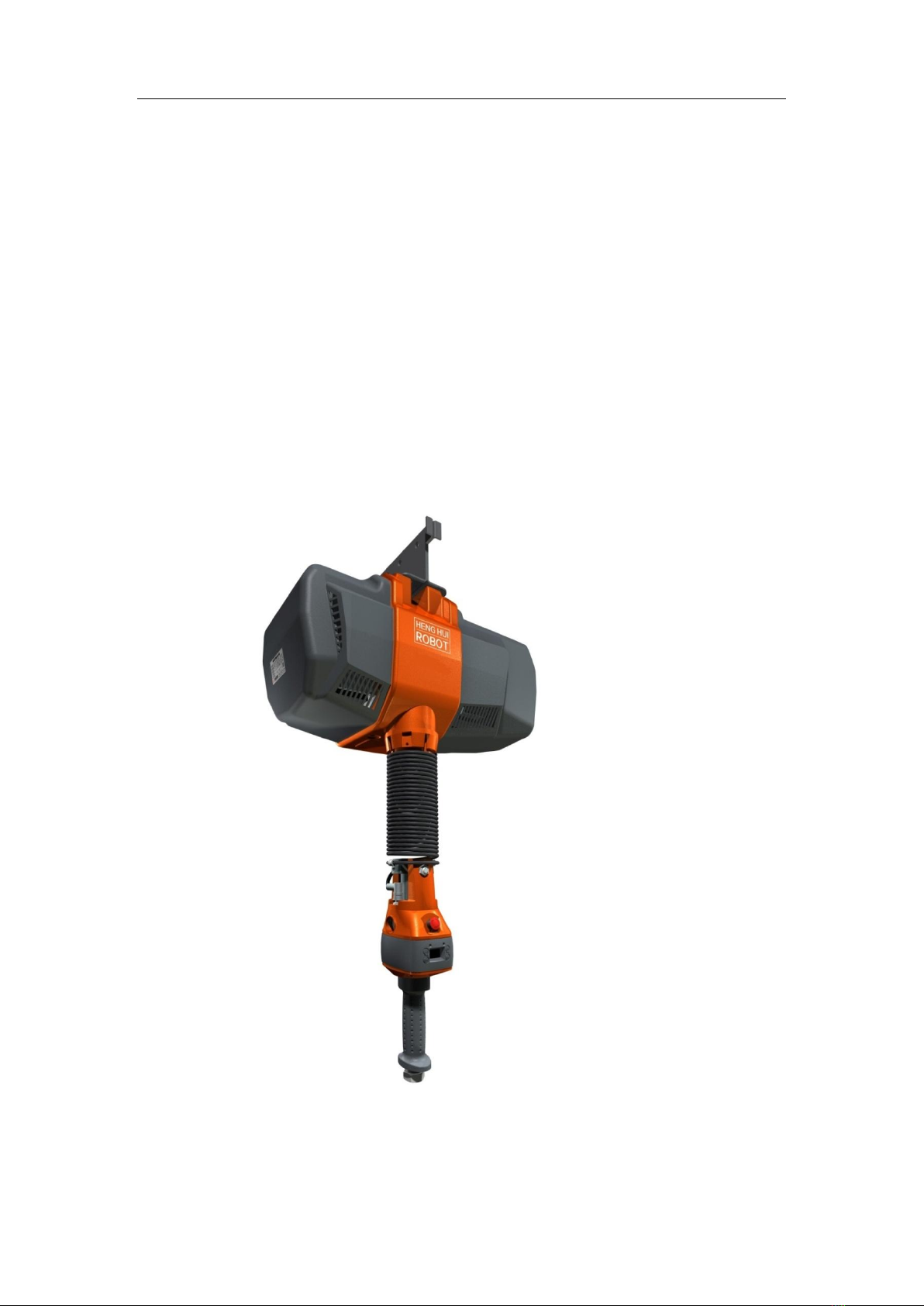
1.3.4 Forced cooler
The intelligence aided lifting equipment is provided with a temperature sensor (Fig. 1. 4). It
is configured to detect the real-time temperature of braking resistor. In case that the detected
temperature is above 50 °C, the DC fan will produce forced air to cool the braking resistor. While
in the event that such temperature is above 100 °C, system operation will be suspended until the
temperature drops back to 80 °C. This device is applied only for 200 KG, 300 KG and 600 KG
types.
Intelligence Aided Lifting Equipment
11
Fig. 1. 4 Forced cooling device
1.3.5 Emergency stop button
By pressing the emergency stop button on the handle (Fig. 1. 5), manual operation or
suspension lifting of the equipment will be disabled other than menu viewing or editing. While the
emergency stop brakes the equipment by direct control of the motor through hardware!
In case that maintenance and service, parameter setting, system upgrade and power-on
standby are performed with the equipment electrified, the emergency stop button must be kept
pressed and locked.
Note:
If the emergency stop button is pressed during equipment movement, it will be forced to stop
immediately. Therefore, please do not press the emergency stop button at will other than a true
emergency under heavy-load or fast movement, otherwise equipment damage or personal injury
may occur!
Fig. 1. 5 Emergency stop button

Intelligence Aided Lifting Equipment
12
Chapter II Overview
2.1 Introduction
The intelligence aided lifting equipment is a material handling device that conforms to
human engineering, comprising of servo drives, servo motors, decelerators, sensors and relevant
structures and controlled by a micro-processor. It features easy operation, high precision,
intelligence, controllable speed, safety and reliability, etc.. The intelligence aided lifting
equipment produced by us includes four types by rated lifting capacity, i.e. 80KG, 200KG, 300KG
and 600KG.
2.2 Major application and scope
Automobile industry (including engines, gearboxes, new energy battery assembly, etc.)
Finish machining
Machinery manufacturing and processing
Energy industry
Handling work with high repeatability
Parts assembly
Warehouse loading and unloading
2.3 Main components and functions
Intelligence aided lifting equipment consists of three major parts as follows1:
Main engine (Fig. 2 1): The main engine comprises mainly of a servo drive, a servo motor, a
decelerator, sensors and a main control panel. It is designed to provide power necessary for the
device to achieve accurate control and lifting, and to process signals.
Spring cable (Fig. 2 2): transmit signals between the main control and the handle, including
lifting orientation, lifting speed, emergency stop and fault signals.
Coaxial sliding handle (Fig. 2 3): consists of control panel, display, handle sliding circle,
displacement sensor and infrared sensor. A handle serves as the main interface between operators
and lifting equipment, by which users may control the lifting of equipment. Users may also
acquire the applicable information through the display.
1A non-derivative combination

Intelligence Aided Lifting Equipment
13
Fig. 2 1 Main unit
Fig. 2 2 Spring cable
Fig. 2 3 Coaxial sliding handle
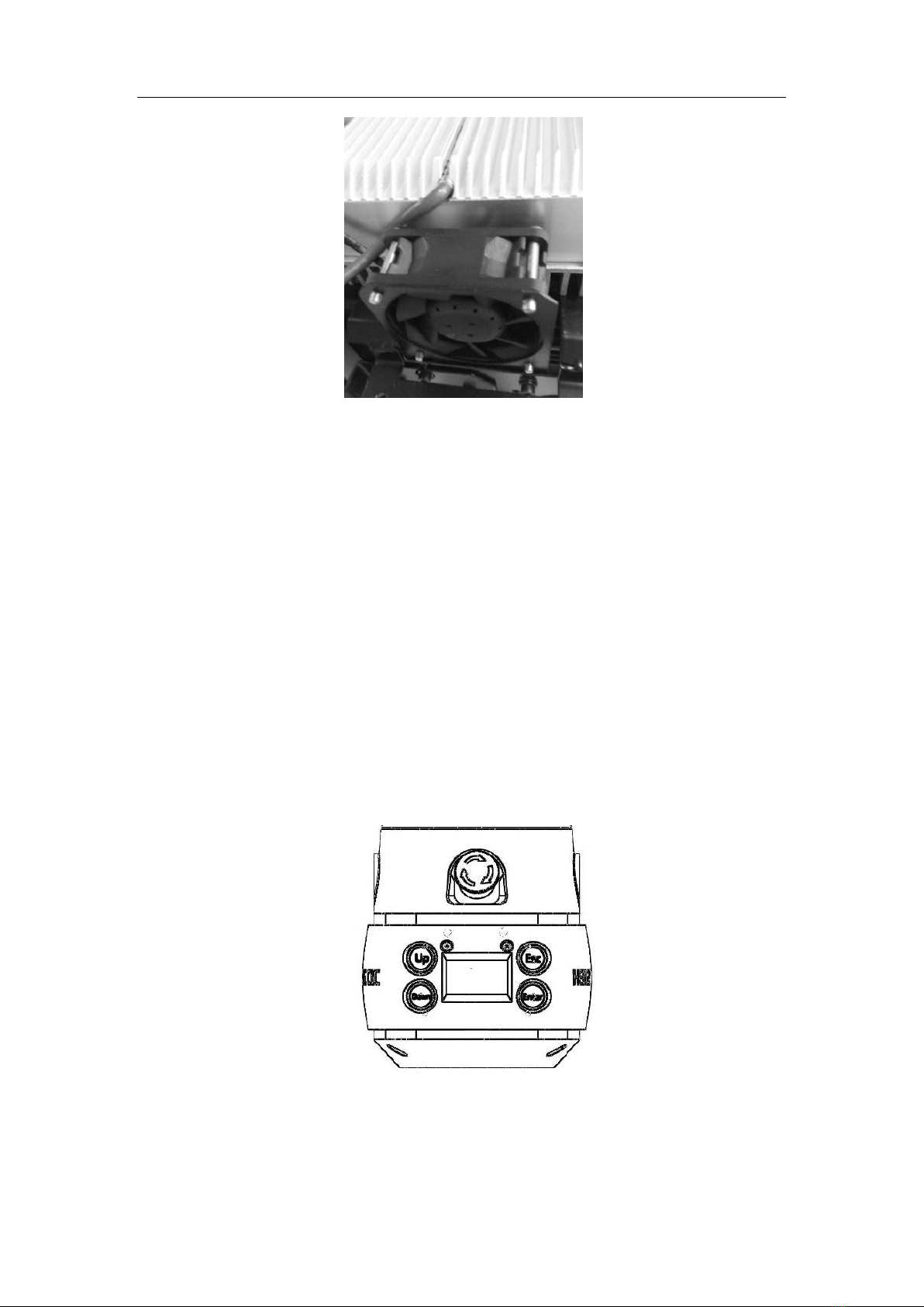
2.4 Types of handles
Apart from a coaxial sliding handle, the intelligence aided lifting equipment may be provided
with a CVT handle, a remote installation sliding handle, an all-touch handle, a wireless handle and
a coaxial pressure handle, depending on the varying station requirements.
CVT handle (Fig. 2. 4): applies to a workplace with limited height and inaccessible to
operators. Users can control equipment lifting through UP and DOWN and acquire corresponding
information through the display. This type of handles may be integrated into the terminal fixture or
hung vertically beneath the main engine.
Sliding handle for remote installation (Fig. 2. 5): applies to a workplace with limited height
and inaccessible to operators. This type of handles can be integrated into the fixture of or secured
externally on a terminal. Its functions resemble a coaxial sliding handle.
All-touch handle (Fig. 2. 6): provided with a built-in pressure sensor. When the force applied
on the handle varies, the equipment moves.
Wireless handle (Fig. 2. 7): allows to remotely control the main engine, applicable to a
workplace inaccessible to operators. This kind of handles provides functions of Fast Gear
Operation, Slow Gear Operation, Suspension Switch and Suspension Unloading Switch.
Coaxial pressure handle: provided with a built-in pressure sensor. When the force applied to
the rubber handle varies, the equipment moves.
Intelligence Aided Lifting Equipment
14
Fig. 2. 4 CVT handle
Fig. 2. 5 Sliding handle for
remote installation
Fig. 2. 6 All-touch
handle
Fig. 2. 7 Wireless
handle
2.5 Signal connection line
In addition to spring wires, the straight connection wires of stepless handles (straight or spring
wires), folding extension wires, H360-handle connection wire A, and H360--handle connection
wire C, depending on different models and handles, can also be used for the connection between
the host and the handles of the intelligent lifting equipment, with the following functions:
Spring wires: connecting the host with a coaxial sliding handle or H360 sliding circle.
Straight connection wires of stepless handles: connecting the host with stepless speed-changing
handle.
Folding extension wires: generally used for the connection of the host and the spring wires
(straight connection wires of stepless handles) in a folded arm
H360-handle connection wire A: connecting H360 sliding circle and remotely installed sliding
handle.
H360-handle connection wire C: connecting H360 sliding circle and stepless speed-changing
handle or all-touch handle.
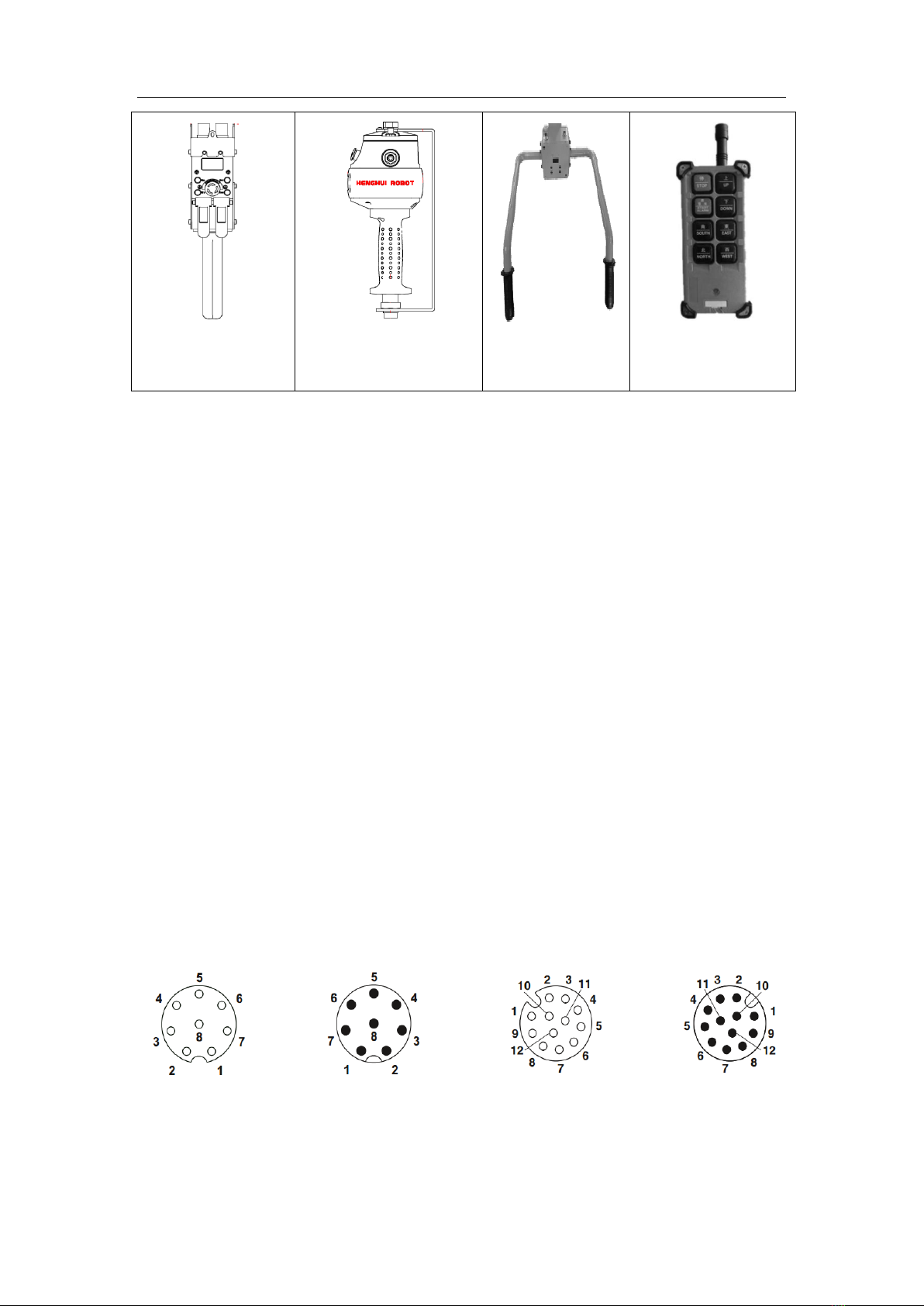
2.5.1 Wire map of signal connection line
Numbering and definition of the pins for 8-core connector and 12-core connector are given in
Fig. 2.8.
Hole-type, 8-core
Needle-type, 8-core
Hole-type, 12-core
Needle-type, 12-core
Fig. 2. 8 Numbering and definition of pins
The wire map of pins for connectors at both ends of spring wires, folding extension wires and
straight connection wires of stepless handles is shown below:

Intelligence Aided Lifting Equipment
15
Needle
Hole
The wire map of pins for connectors at both ends of H360-handle connection wire A is shown
below:
Hole
Hole
The wire map of pins for connectors at both ends of H360-handle connection wire C is shown
below:
Hole
Hole
2.6 H360 Sliding Circle
The H360 sliding circle (Fig. 1. 6) is used in combination with a remote installation sliding
handle, CVT handle or all-touch handle. Its built-in sliding circle and air tube connector
effectively eliminate the twist of signal cables and air tubes.

Intelligence Aided Lifting Equipment
16
Fig. 1. 6 H360 sliding circle
2.7 Composition and meanings of model
The following is the model composition and meanings of a main engine of intelligence aided
lifting equipment.
2.8 Nameplate
1. Type and model
The type and model of the said equipment.
2. Rated capacity
Rated lifting capacity of the equipment.
3. Lifting height
Maximum stroke of the equipment.
4. Product No.
Sequential figures indicating the production number of a product.
5. Input voltage
The power supply voltage of the said type, at 50HZ.
6. Rated power
IAD-H080-500-A10
Product Version
Length of steel cable (cm):
Hoisting capacity (kg):
Product code: IntelligenceAided Lifting Equipment

Intelligence Aided Lifting Equipment
17
The rated power of the said type.
7. Operation speed
The maximum operation speed of the equipment.
8. QR code and CE certification
Product information can be acquired by scanning the QR code. This product has passed CE certification.
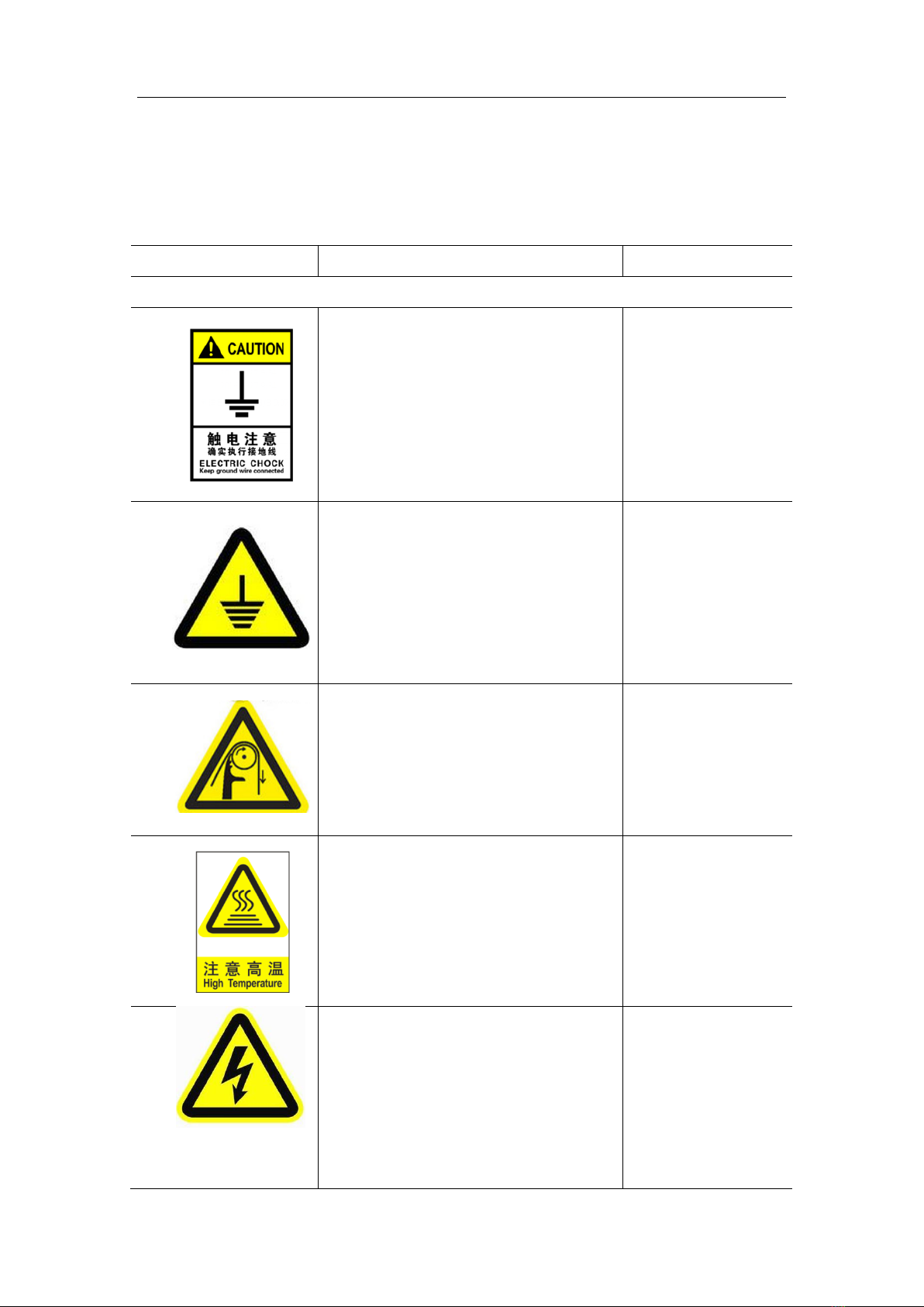
2.9 Basic operation interface
The basic operation interface of intelligence aided lifting equipment (Fig. 2. 9) comprises of
an emergency stop button, “UP”button, “DOWN”button, “ESC” button, “ENT” button, LCD
display and status indication lamps. Users may carry out operations on the system through
external buttons and acquire corresponding information through the LCD display. Refer to Table 1
for details.
Fig. 2. 9 Basic operation interface
Table 1
S/N
Corresponding
function
Function description
1
Emergency stop
switch
If pressed, equipment enters emergency stop mode, under
which equipment lifting will be banned;
2
Failure indicating
lamp
Off: equipment operates normally;
On: Equipment fails or is under emergency stop mode;
3
Running indicator
Blinking slowly: equipment operates normally (lock mode
and emergency stop mode);
Blinking quickly: Unloading mode;
Shining constantly: Suspension/suspension unloading mode;
4
“UP”button
Select “UP”button on the menu;
By holding it (for 2 s) under the lock mode, the equipment
enters “suspension unloading mode”;
5
“ESC”button
Return to the previous menu;
By holding it (for 2 s) under the lock mode, the equipment

Intelligence Aided Lifting Equipment
18
enters “suspension mode”;
6
“DOWN”button
Select “DOWN”button on the menu;
By holding it (for 2 s) under the lock mode, the equipment
enters “unloading mode”;
7
“ENT”button
Enter the next menu;
Execute the saving operation;
8
LCD screen
Displays operation modes, relative weight, relative position
and fault alarms;
2.10 Main technical parameters
The main technical parameters of the intelligence aided lifting equipment are shown in Table 2.
Table 2
Main engine model
IAD-H80
IAD-H200
IAD-H300
IAD-H600
Load (weight and tool)
(KG)
80
200
300
600
Maximum lifting speed
under manual hold mode
- no load (m/Min)
40
30
15
7.5
Maximum lifting speed
under manual hold mode
- full load (m/Min)
30
23
12.8
6.8
Maximum lifting speed
under suspension mode -
no load (m/Min)
36
27
13.5
6.75
Maximum lifting speed
under suspension mode -
full load (m/Min)
27
20.7
12.15
6.08
Maximum lifting height
(m)
3.50
3.50
3.50
1.70
Main power supply
(VAC)
Single phase
200 - 230 V
Single phase
200 - 230 V
Three-phase
200 - 230 V
Three-phase
200 - 230 V
Frequency of main power
supply (HZ)
50HZ
50HZ
50HZ
50HZ
Maximum current (A)
10
12
15
15
Lifting medium (stainless
∅5.00 mm
∅5.00 mm
∅5.00 mm
∅6.50 mm

Intelligence Aided Lifting Equipment
19
steel cable)
Working environment
temperature range
-10-60℃
-10-60℃
-10-60℃
-10-60℃
Humidity range of
working environment (no
condensation)
0-93%
0-93%
0-93%
0-93%
Soft limit
Yes
Yes
Yes
Yes
Weight display accuracy
(KG)
1% * rated
load
1% * rated
load
1% * rated load
1% * rated load
CE certified
Yes
Yes
Yes
Yes
Cooling method
Natural wind
Natural wind
and forced
wind
Natural wind
and forced wind
Natural wind
and forced wind
2.11 Basic dimensions
80KG, 200KG, 300KG Intelligence Aided Lifting Equipment Basic Dimensions Table 3 (Fig.
2 10right). See attachments for detailed dimensions.
600KG Intelligence Aided Lifting Equipment Basic Dimensions 3 (Fig. 2 10left). See
attachments for detailed dimensions.
Note: D is the min. size.
Table 3
Model
IAD-H80
IAD-H200/IAD-H300
IAD-H600
A (mm)
285
312
312
B (mm)
670
670
670
C (mm)
462
462
477
D (mm)
610
610
1085
E (mm)
410
410
410
F (mm)
122
122
122
G (mm)
142
142
142
H (mm)
141
141
141

Intelligence Aided Lifting Equipment
20
Fig. 2 10 Dimension
2.12 Main components
Intelligence Aided Lifting Equipment Main Components Information Table 4.
Table 4
Model
IAD-H80
IAD-H200
IAD-H300
IAD-H600
Servo drivers
Delta (0.75KW)
Delta (1.5KW)
Delta (2KW)
Delta
(2KW)
Servo motor
Delta (0.75KW)
Delta (1.5KW)
Delta
(2KW)
Delta
(2KW)
Gear reducer
Planetary gear
Planetary gear
Planetary
gear
Planetary
gear
Switching power
supply
LRS-100-24
(MEAN WELL)
LRS-100-24
(MEAN
WELL)
LRS-100-24
(MEAN
WELL)
LRS-100-24
(MEAN
WELL)
Main control
board
Henghui
Henghui
Henghui
Henghui
Structural Parts
Henghui
Henghui
Henghui
Henghui
This manual suits for next models
3
Table of contents
Popular Lifting System manuals by other brands

Presto Lifts
Presto Lifts M100 Installation, operation and service manual

Freedom Lift Systems
Freedom Lift Systems Trus-T-Lift 750 Owner's operation manual

Nexion
Nexion Molnar CM245-A Installation, operation & maintenance instructions

TradeQuip
TradeQuip 6007T owner's manual

unicraft
unicraft SHB 3 instruction manual

EZ Carrier
EZ Carrier EZCL user manual


