unicraft SHB 3 User manual

SHB 3
SHB 3
Instruction Manual
Scissor lift
SHB 3

2SHB 3 | Version 1.02
Imprint
Product identification
Scissor lift Item number
SHB 3 6240030
Manufacturer
Stürmer Maschinen GmbH
Dr.-Robert-Pfleger-Str. 26
D-96103 Hallstadt
Fax: 0049 (0) 951 96555 - 55
E-Mail: [email protected]
Internet: www.unicraft.de
Indications regarding the operating instructions
Original instructions
Edition: 12.06.2020
Version: 1.02
Language: English
Author: FL
Indications regarding the copyright
Copyright © 2020 Stürmer Maschinen GmbH, Hallstadt,
Germany.
The contents of these operating instructions are the sole
property of the company Stuermer. Passing on as well
as copying of this document, the use and distribution of
its content are prohibited if not explicitly permitted. Con-
traventions are liable to compensation.
Subject to technical modifications and error.
Contents
1 Einführung ...............................................................3
1.1 Urheberrecht ...................................................... 3
1.2 Kundenservice.................................................... 3
1.3 Haftungsbeschränkung...................................... 3
2 Sicherheit .................................................................3
2.1 Symbolerklärung................................................. 3
2.2 Verantwortung des Betreibers............................ 4
2.3 Personalanforderungen...................................... 5
2.4 Persönliche Schutzausrüstung.......................... 5
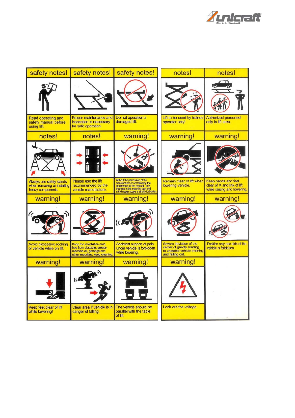
2.5 Sicherheitskennzeichnung an der Hebebühne.. 5
2.6 Warnhinweise an der Hebebühne...................... 6
2.7 Allgemeine Sicherheitsvorschriften .................... 7
2.8 Sicherheitsvorrichtungen.................................... 7
3 Bestimmungsgemäße Verwendung ......................8
3.1 Vorhersehbarer Fehlgebrauch ........................... 8
3.2 Restrisiken .......................................................... 8
4 Technische Daten....................................................8
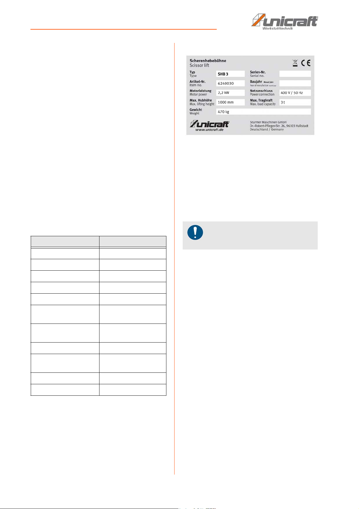
4.1 Typenschild ........................................................ 8
5 Transport, Verpackung und Lagerung ..................8
5.1 Transport ............................................................ 8
5.2 Verpackung ........................................................ 9
5.3 Lagerung ............................................................ 9
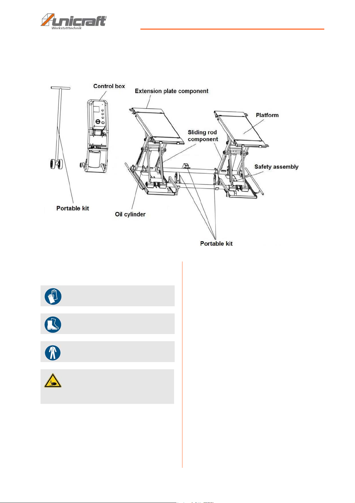
6 Gerätebeschreibung ...............................................9
7 Montage..................................................................10
7.1 Anforderungen an den Aufstellort .................... 10
7.2 Aufstellen der Hebebühne................................ 10
8 Hydraulischer und Elektrischer Anschluss ........11
8.1 Elektrischer Anschluss ..................................... 11
8.2 Hydraulischer Anschluss.................................. 11
9 Prüfpunkte nach der Installation .........................12
10 Bedienung............................................................12
10.1 Beschreibung des Steuerpults....................... 13
10.2 Last heben...................................................... 13
10.3 Last absenken ................................................ 13
11 Pflege, Wartung und Instandsetzung ................14
11.1 Pflege durch Reinigung.................................. 14
11.2 Wartung und Instandsetzung/Reparatur ....... 14
11.2.1 Prüfungsintervalle......................................14
11.3 Schmierstellen an der Hebebühne................. 15
12 Störungsbeseitigung ..........................................15
13 Entsorgung, Wiederverwertung von Altgeräten...16
13.1 Außer Betrieb nehmen.................................... 16
13.2 Entsorgung von Schmierstoffen/Ölen............. 16
13.3 Entsorgung über kommunale Sammelstellen .... 16
14 Ersatzteile ............................................................16
14.1 Ersatzteilbestellung ........................................ 16
14.2 Ersatzteilzeichnungen .................................... 17
15 Elektro-Schaltplan...............................................18
16 Hydraulik-Schaltplan...........................................19
17 Druckluft-Schaltplan ...........................................19
18 EU-Konformitätserklärung .................................20

Introduction
SHB 3 | Version 1.02 3
1Introduction
You have made a good choice by purchasing the UNI-
CRAFT Scissor lift.
Read the operating manual thoroughly before com-
missioning the machine.
It gives you information about the proper commission-
ing, intended use and safe and efficient operation and
maintenance of your Scissor lift.
The operating manual is part of the Scissor lift package.
Always keep this operating manual in the location where
your Scissor lift is being operated. All local accident pre-
vention regulations and general safety instructions for
the operating range of your Scissor lift must also be com-
plied with.
1.1 Copyright
The contents of these instructions are copyright. They
may be used in conjunction with the operation of the
Scissor lift. Any application beyond those described is
not permitted without the written approval of Stürmer
GmbH. For the protection of our products, we shall regi-
ster trademark, patent and design rights, as this is pos-
sible in individual cases. We strongly oppose any infrin-
gement of our intellectual property.
1.2 Customer service
Please contact your dealer if you have questions con-
cerning your Scissor lift or if you need technical advice.
They will help you with specialist information and expert
advice.
Germany:
Stürmer Maschinen GmbH
Dr.-Robert-Pfleger-Str. 26
D-96103 Hallstadt
Repair service:
Fax: 0951 96555-111
E-Mail: [email protected]
Internet: www.unicraft.de
Spare part orders:
Fax: 0951 96555-119
E-Mail: [email protected]
We are always interested in valuable experience and
knowledge gained from using the application which then
could be shared and be valuable to develop our products
even further.
1.3 Limitation of Liability
All information and notes in these operating instructions
were summarised while taking applicable standards and
rules, the state-of-the-art technology and our long-term
knowledge and experiences into consideration.
In the following cases the manufacturer is not liable for
damages:
- Non-observance of the operating instructions,
- Inappropriate use
- Use of untrained staff,
- Unauthorised modifications
- Technical changes,
- Use of not allowed spare parts.
The actual scope of delivery may deviate from the ex-
planations and presentations described here in case of
special models, when using additional ordering options
or due to latest technical modifications.
The obligations agreed in the delivery contract, the gen-
eral terms and conditions as well as the delivery condi-ti-
ons of the manufacturer and the legal regulations at the
time of the conclusion of the contract are applicable.
2 Safety
This section provides an overview of all important safety
packages for the protection of operating personnel as
well as for safe and fault-free operation. Other task-ba-
sed safety notes are included in the paragraphs of the in-
dividual phases of life.
2.1 Symbol explanation
Safety instructions
The safety notes in these operating instructions are high-
lighted by symbols. The safety notes are introduced by
signal words which express the concern of the risk.
DANGER!
This combination of symbol and signal words indi-
cates an imminently dangerous situation which may
lead to death or severe injury if not avoided.
WARNING!
This combination of symbol and signal words indi-
cates a potentially dangerous situation which may
lead to death or severe injury if not avoided.

4SHB 3 | Version 1.02
Safety
Tips and recommendations
It is necessary to observe the safety notes written in
these operating instructions in order to reduce the risk of
personal injuries and damages to property.
2.2 Obligations of the operating company
of the operator
The operating company is the person who operates the
Scissor lift for business or commercial reasons by her-
self, or leaves it to a third party for use or application, and
who bears the legal product responsibility for the protec-
tion of the user, the staff or for third par-ties.
Obligations of the operating company
If the Scissor lift is used for commercial purposes, the
operating company of the Scissor lift must comply with
the legal working safety regulations. Therefore, the
safety notes in this operating manual, as well as the
safety, accident prevention and environment protection
regulations applying for the area of application of of the
Scissor lift must be met. The following applies in particu-
lar:
- The operating company must be informed about
the applying industrial safety regulations and fur-
ther analyse hazards resulting from the special
working conditions at the place of use of the Scis-
sor lift. She must implement these in form of opera-
ting manuals for the operation of the Scissor lift.
- During the entire lifetime of of the Scissor lift, the
operating company must verify whether the opera-
ting manuals prepared by her correspond to the
current status of the regulations, and must adapt
these if necessary.
- The operating company must unambiguously reg-
ulate and determine the responsibilities for instal-
lation, operation, troubleshooting, maintenance
and cleaning.
- The operating company must ensure that all per-
sons who work with the Scissor lift, have read and
understood this manual. Furthermore she must in-
struct the staff in regular intervals and in-form them
about the hazards.
- The operator must provide the necessary protec-
tive equipment to the staff and order the use of the
necessary protective equipment in a binding way.
Furthermore the operating company is responsible to
keep the Scissor lift always in a technically flawless
state. Thus, the following applies:
- The operator must ensure that the maintenance in-
tervals described in this manual are kept.
- The operator must have all safety devices checked
regularly for their good working order and their in-
tegrity.
CAUTION!
This combination of symbol and signal words indi-
cates a potentially dangerous situation which may
lead to slight or minor injury if not avoided.
ATTENTION!
This combination of symbol and signal words indi-
cates a possibly dangerous situation which may lead
to property and environmental damages if they are
not avoided.
NOTE!
This combination of symbol and signal words indi-ca-
tes a potentially dangerous situation which may lead
to material or environmental damage if not avoided.
Tips and recommendations
This symbol highlights useful tips and recommendati-
ons as well as information for efficient and trouble-
free operation.

Safety
SHB 3 | Version 1.02 5
2.3 Requirements to staff
Qualifications
The different tasks described in this manual represent
different requirements to the qualification of the persons
entrusted with these tasks.
Only persons reliable working procedures can be ex-
pected from, are allowed to perform all works. Persons
the responsiveness of which is affected by e. g. drugs,
alcohol or medication, are not allowed to work with the
machine.
The qualifications of the personnel for the different tasks
are mentioned below:
Operator
The operator is instructed by the operating company
about the assigned tasks and possible risks in case of
improper behaviour. Any tasks which need to be perfor-
med beyond the operation in the standard mode must
only be performed by the operator if it is indicated in
these instructions and if the operating company expres-
sively commissioned the operator.
Qualified personnel
Due to their professional training, knowledge and expe-
rience as well as their knowledge of relevant regulations
the specialist staff is able to perform the assigned tasks
and to recognise and avoid any possible dangers them-
selves.
Manufacturer
Certain works may only be performed by specialist per-
sonnel of the manufacturer. Other personnel is not au-
thorized to perform these works. Please contact our cus-
tomer service for the execution of all arising work.
2.4 Personal protective equipment
The personal protective equipment serves to protect per-
sons against impairments of safety and health while wor-
king. The staff member has to wear personal protective
equipment while performing different tasks on and with
the machine which are indicated in the individual para-
graphs of these instructions.
The personal protective equipment is explained in the
following paragraph:
2.5 Safety labels on the machine
Safety markings and instructions are attached to the lif-
ting platform (Fig. 1), which must be observed and follo-
wed.
Fig. 1: Safety labels
The safety markings affixed to the lifting platform must
not be removed. Damaged or missing safety markings
can lead to incorrect handling, personal injury and da-
mage to property. They must be replaced immediately.
If the safety markings are not visible and understandable
at first glance, the lift must be taken out of service until
new safety markings have been applied.
WARNING!
Danger in case of insufficient quali-
fication of the staff!
Insufficiently qualified persons cannot estimate the
risks while using the Scissor lift and expose them-
selves and others to the danger of severe or lethal
injuries.
- Have all works only performed by qualified per-
sons.
- Keep insufficiently qualified persons out of the wor-
king area.
Protective gloves
The protective gloves serve to protect the hands
against sharp components as well as against fric-
tion, abrasions or deep injuries.
Safety boots
Safety boots protect the feet from being crushed, fall-
ing parts and slipping over on slippery ground.
Protective clothes
Protective clothes are made of a tightly fitted fabric
without the protruding parts of low tear strength.

6SHB 3 | Version 1.02
Safety
2.6 Warnings on the lifting platform
Warnings are attached to the lifting platform (Fig. 2), which must be observed and followed.
Fig. 2: Warnings on the lifting platform

Intended use
SHB 3 | Version 1.02 7
2.7 General safety regulations
- Please read this manual carefully before installa-
tion and operation to avoid damage to property and
personal injury due to improper operation.
- Do not work on the machine under the influence of
drugs or alcohol and when you are tired.
- It is not permitted to make any changes to the con-
trol unit or any mechanical unit.
- The lift may only be set up and operated by per-
sons who are familiar with the lift and are aware of
the risks involved in using the lift.
- Do not operate the lift under the influence of drugs,
alcohol or medication.
- The electrical connection may only be carried out
by a qualified electrician.
- Keep the handles dry, clean and free of oil and
grease.
- Keep children and unauthorised personnel away
from the work area.
- Always keep the work area clean and accessible.
- Keep the work area well lit.
- Do not mount the lift on an asphalt surface.
- Read and understand the safety instructions before
operating the lift.
- Before cleaning the machine or carrying out main-
tenance work, switch off the machine and unplug
the power cord.
- Never pull on the mains cable, only on the plug to
disconnect the lift from the mains. Keep the cable
away from heat, oil and sharp edges.
- Never leave the working area while the lift is in ope-
ration.
- Watch your hands and feet when the lift is lowered.
- Always wear the necessary safety equipment (pro-
tective gloves, safety shoes, etc.)
- Never exceed the maximum permitted weight of
the lift.
- Do not rock the vehicle on the lift and do not re-
move heavy components from the vehicle that
could cause excessive weight shift.
- Make sure that all safety precautions are in place
before working near or under the vehicle. Never re-
move safety-relevant components from the lift.
- Do not use the lift if safety-related components are
missing or damaged.
- Lower the lift to its lowest position and disconnect
the power supply.
- Always check the mobility of the lift to ensure per-
formance.
- Ensure regular maintenance. If an irregularity oc-
curs, stop working with the lift immediately and
contact your dealer.
- Only use original UNICRAFT accessories and
spare parts.
2.8 Safety devices
Integrated in the switch box is a hydraulic power unit
which generates the necessary pressure to lift the vehi-
cle. This is controlled by valves and moves the cylinders
and platforms upwards via the scissor mechanism. Du-
ring the lifting process, the safety catches engage to pre-
vent the platforms from lowering in case of a defect in the
hydraulic system.
Fig. 3: Protection device in case of hydraulic failure
The left as well as the right side of the base plate is fixed
with an anti-tipper. This prevents a possible tipping of the
vehicle.
Fig. 4: Device for protection against tipping
3 Intended use
The scissor lift is used exclusively for lifting and lowering
loads, e.g. vehicles, up to the specified maximum load.
Proper use also includes compliance with all the informa-
tion in these instructions. Any use beyond the intended
use or any other use is considered misuse.
NOTE!
The improper use (misuse) of the lift as well as the
disregard of the safety regulations or the operating
instructions exclude any liability of the manufacturer
for resulting damages to persons or objects and
cause the warranty to expire!
Mechanical
Safety Lock
Protection against tipping

8SHB 3 | Version 1.02
Technical Data
Stürmer Maschinen GmbH accepts no liability for design
and technical modifications to the lifting platform.
Claims of any kind for damage due to improper use are
excluded.
3.1 Predictable misuse
- Lifting of vehicles that exceed the specified maxi-
mum load.
- Lifting of vehicles that are not sufficiently secured
on the lift.
- Lifting of persons or other objects.
3.2 Residual risks
- Risk of crushing when lowering the lift.
- Movement of the lifted load with insufficient safety.
- Unforeseen lowering of the lifting platform in case
of leakage in the hydraulic system or insufficient
protection with support blocks.
4 Technical Data
4.1 Type plate
Fig. 5: Type plate SHB 3
5 Transport, Packaging, Storage
5.1 Transport
Check the scissor lift after delivery for visible transport
damage. If you discover any damage, report it immedi-
ately to the transport company or the dealer.
5.2 Packaging
All packaging materials and packaging aids used are
recyclable and must always be sent for material recy-
cling.
Shredded cardboard packaging components should be
sent to the waste paper collection.
The films are made of polyethylene (PE), the padded
parts of polystyrene (PS). These materials are to be han-
ded in at a reusable material collection point or to your
local waste disposal company.
5.3 Storage
Oil the scissor lift and store it in a frost-free and dry env-
ironment. Store the scissor lift only with the scissor lift lo-
wered and the drain valve closed. Do not place anything
on the scissor lift.
If you do not use the scissor lift for a longer period of
time, then:
- Disconnect the lift from the power source.
- Empty the oil tank.
- Lubricate the moving parts with hydraulic oil.
Model SHB-3
Dimensions (L x W) 1943 mm x 1954 mm
Height min. / max. 125 mm - 1000 mm
Weight 470 kg
Supply voltage 400 V
Load-bearing capacity 3 t
Platform height min. /
max.
110 mm - 1000 mm
Lifting time platform
height min. to max
30 s
Lifting speed loaded 33 mm/s
Dimensions Platform
L x W
1420 mm x 460 mm
Drive motor output 2,2 kW
Air working pressure 8 bar
NOTE!
Protect the scissor lift from moisture.

Description
SHB 3 | Version 1.02 9
6 Description
Illustrations in this operating manual may differ from the original.
Fig. 6: Description
7 Assembly
The following tools are required for assembly:
- Electric drill
- Wrench
- Screwdriver
- Hammer
- Spirit level
7.1 Requirements for the installation site
The lifting platform must be set up on a level and solid
base. It must be ensured that there is sufficient freedom
of movement for working. The installation site should
meet the following criteria:
- The substrate must be level, solid and vibration-
free with a compressive strength of more than 3kg /
mm², a difference in level of less than 5 mm and a
minimum thickness of 200 mm (Fig.7). This thick-
ness is required for fixing with the ground anchors.
- The substrate must not allow lubricants to pass th-
rough.
- The installation or working area must be dry and
well ventilated.
- There must be sufficient space for the operating
personnel, for adjustment and maintenance work.
- The installation site must have good lighting.
- A new concrete floor must be dry for at least 28
days before the lift can be installed.
Use protective gloves!
Use protective boots!
Use Protective clothes!
CAUTION!
Risk of crushing!
There is a risk of injury to upper limbs when working
improperly on the scissor lift.

10 SHB 3 | Version 1.02
Hydraulic and electrical connection
Fig. 7: Installation plan
7.2 Setting up the Scissor lift
Step 1: Unpack the machine and check for damage and
completeness.
Step 2: Attach the transport rollers and transport the lif-
ting platform to the installation site using the dra-
wbar (Fig.8).
Fig. 8: Driving equipment
Step 3: Mount the protective cover on both sides using
the Allen screws.
Fig. 9: Driving direction
Step 4: If necessary, fix the lift to the ground.
8 Hydraulic and electrical connection
8.1 Electrical connection
Only use the lift in a dry environment. Operate the lift
only with a power supply that meets the following requi-
rements:
- the mains voltage and the frequency of the power
supply must correspond to the specifications on
the rating plate
- Protection with a residual current circuit breaker
(RCD).
- Use of a grounding contact socket (properly groun-
ded socket).
- Lay the power cable so that it does not interfere
with work and cannot be damaged.
- Protect the power cord from heat, aggressive li-
quids and sharp edges.
CAUTION!
Danger of injury due to an unstably positioned lifting
platform! Check the stability of the machine after set-
ting it up on a stable surface.
CAUTION!
Observe the weight of the lifting platform! The lifting
platform may only be set up by two persons together.
Check that the auxiliary equipment is sufficiently di-
mensioned and has sufficient load capacity.
DANGER!
In case of a test run of the lifting platform no vehicle may
be placed on the lifting platform.
Driving
direction
Driving
equipment
DANGER!
Danger to life through electric
shock!
There is a danger to life when in contact with live
components. Switched-on electrical components can
execute uncontrolled movements and cause serious
injuries.
- Unplug the machine from the mains before making
adjustments to the machine.
DANGER!
All work on the electrical installation may only be car-
ried out by a qualified electrician.

Hydraulic and electrical connection
SHB 3 | Version 1.02 11
Step 1: Connect the limit switch wiring inside the electri-
cal box as shown in Figure 10.
01 Wiring to 01 Terminal
03 Wiring to 03 Terminal
Fig. 10: Electrical connection
Step 2: Connect the lift to the power supply.
Check motor rotation direction
After electrical connection, check that the direction of
rotation of the motor is correct. If the direction of rotation
is wrong, the connections of the phase lines must be re-
placed.
If equipped with a phase inverter:
Press the disc in the plug with a screwdriver and turn it
by 180°.
Fig. 11: Change motor direction of rotation
8.2 Hydraulic connection
Step 1: Prepare the wires and cables for the lift connec-
tions (Fig.12).
Fig. 12: Hydraulic connection
Step 2: Connect the hydraulic line to the hydraulic
pump. The hoses can be arranged freely on
each side.
Fig. 13: Connection to the hydraulic pump
Step 3: Connect the compressed air (the air pressure
range is between 1.0 and 1.5 kg/cm2 ) to the air
connection of the oil-water separator of the
pump station.
Step 4: Then connect the safety valve to the air outlet of
the pneumatic solenoid valve of the pumping
station.
Fig. 14: Compressed air connection
Step 5: Fill the oil tank with hydraulic oil The distance
between the oil level and the upper edge of the
oil tank should be in the range of 10 to 30 mm.
(Measurement with dipstick on the tank cap)
DANGER!
All work on the hydraulic installation may only be car-
ried out by a qualified person.

12 SHB 3 | Version 1.02
Test points after installation
9 Test points after installation
Never try to operate the lift before you have tested it.
This step is very important and necessary to make sure
that all cables are correctly fixed and that there is no
danger of a possible leakage of the cable.
- Check all hoses and connections. The lifting plat-
form may only be put into operation if there are no
leaks.
- Make sure that the line is clean and free of foreign
objects.
- All screw connections must be tight.
Fig. 15: Check points
10 Operation
10.1 Description of the control panel
Fig. 16: Control panel
WARNING!
Danger to life!
There is danger to life for the operator and other per-
sons if the following rules are not observed.
- Before operating under load, carry out a test to
check all functions without load.
- The lifting platform may only be operated by a trai-
ned and experienced person.
- The operator must not work when under the influ-
ence of alcohol, drugs or medicines.
- The operator must not work if he is overtired or suf-
fers from illnesses that impair concentration.
- Disconnect the lift from the power source before ma-
king adjustments.
- Distribute the weight centrally on the scissor lift.
- Never work under the lifted load without being addi-
tionally secured with trestles.
- Make sure that the safety catches are engaged be-
fore starting work.
- Lower the load when leaving the workplace.
- Do not allow anyone to be under the lift while it is
being raised or lowered..
CAUTION!
Risk of crushing!
There is a risk of injury to upper and lower limbs
when working improperly with the scissor lift.
Check points
YES / NO
Same height of both platforms
Oil hoses tightly connected
Electrical cabling correctly connected
Valves of the oil pump unit fixed
Wear protective gloves!
Wear safety shoes!
Wear protective work clothing!
NOTE!
- The operating personnel must be familiar with the
operation and functions as well as the safety regu-
lations when operating the scissor lift.
- The operator must ensure that the operating per-
sonnel receive the necessary training.
1: Power supply
indicator light
2: Fault indicator
light
3:Lifting the plat-
form
4:Lower the lifting
platform
5:Lock lifting plat-
form
6: Emergency
stop button
7: Main switch

Care, maintenance and repair
SHB 3 | Version 1.02 13
10.2 Lift a load
Step 1: Move the vehicle onto the lift. The platforms must
be placed in the middle between the wheels and
lengthwise in the middle under the vehicle.
Step 2: Attach the four rubber blocks to the designated
mounting points under the vehicle.
Step 3: Set the main switch to ON and unlock the emer-
gency stop button.
Step 4: Press the UP button until the rubber blocks touch
the vehicle. Check that the rubber blocks are
properly positioned under the mounting points.
Step 5: Press the UP button until the wheels have just
left the ground and check that the vehicle is
stable on the rubber blocks.
Step 6: Press the UP button and lift the load evenly to the
desired height.
Step 7: Press the LOCK button to activate the mechani-
cal safety lock.
Step 8: Check that the car is stable. Place stands under
the platforms before working under the car.
Step 9: The main switch can be set to "0" to prevent un-
intentional operation.
10.3 Lower a load
Step 1: Set the main switch to "1".
Step 2: Lift the load until the support stands are free.
Step 3: Remove the support stands.
Step 4: Press and hold the DOWN button to open the
safety lock and lower the load. An alarm signal is
heard throughout the lowering process.
Step 5: Remove rubber blocks.
Step 6: Set the main switch to OFF.
Step 7: Lower the vehicle from the lift.
11 Care, maintenance and repair
11.1 Care through cleaning
The scissor lift must always be kept in a clean condition.
All plastic parts and painted surfaces should be cleaned
with a soft, damp cloth and a little neutral cleaner.
Remove excess grease or leaked oil with a dry and lint-
free cloth.
11.2 Maintenance and repair
If the scissor lift does not function properly, contact a
specialist dealer or our customer service. The contact
details can be found in chapter 1.2 Customer service.
All protective and safety devices must be reinstalled im-
mediately after repair and maintenance work has been
completed.
NOTE!
The operator must have sufficient freedom of move-
ment.
DANGER!
Danger to life through electric
shock!
There is a danger to life when in contact with live
components. Switched-on electrical components can
execute uncontrolled movements and cause serious
injuries.
- Before starting cleaning and maintenance work, pull
out the mains plug.
- Connection and repair of the electrical equipment
may only be carried out by a qualified electrician.
Wear protective gloves!
NOTE!
Never use harsh cleaning agents for any cleaning
work. This can lead to damage or destruction of the
device.
DANGER!
Maintenance and repair work may only be carried out
by instructed persons.

14 SHB 3 | Version 1.02
Care, maintenance and repair
11.2.1 Inspection intervals
Daily
- Check all screw connections for tightness.
- Check the connection of the oil hoses. There must
be no leakage.
- Check the scissor lift for external damage before
each use.
- Check the electrical connections. Make sure that
all connections are in good condition.
- Make sure that all safety instructions on the scissor
lift are clearly legible.
Weekly
- Check the flexibility of moving parts and lubricate
all bearings.
- Check that the safety pins are well secured.
- Check the operating conditions of the safety de-
vices.
- Check the amount of oil remaining in the oil tank.
The amount of oil is sufficient if the lift can be rai-
sed to the highest position. Otherwise the oil quan-
tity is insufficient.
Monthly
- Check all screws, bolts and nuts, retighten if neces-
sary.
- Check the hydraulic system for leaks and tighten
the connections if they are leaking.
- Check the lubrication and wear condition of the mo-
ving parts.
Yearly
- Check the lubrication and wear condition of the mo-
ving parts.
- Empty the oil tank and fill with new hydraulic oil.
- Wash and clean the oil filter and replace it if neces-
sary.
Every three years or more than 5,000 working
hours
- Replace the rotary axes of the scissors, the bea-
rings and the connections of the cables.
11.3 Lubrication points
Fig. 17: Lubrication points

Troubleshooting
SHB 3 | Version 1.02 15
12 Troubleshooting
DANGER!
If one of the following errors occurs, stop working
with the lift immediately. Serious injury could result.
All repairs or replacements must only be carried out
by qualified and trained personnel.
Fault Possible cause Remedy
Engine does not run and the plat-
forms are not lifted
1.Motor is defective
2.Fuse is defective
3.The wire connection is loose
1.Replace the motor
2.Replace the fuse
3.Check connection
Engine runs but the platforms are not
lifted
1.Wrong direction of motor rotation
2.Low oil level
3.The safety valve is damaged
4.The oil hose is loose
1.Change direction of rotation
2.Check the oil level and top up if
necessary
3.Check valve and replace if neces-
sary.
4. Check oil hose and tighten if
necessary.
Increase too slow 1.Low oil level.
2.The pressure relief valve is not
correctly adjusted .
3.Load to be lifted too heavy .
4. Oil filter is clogged .
5. Cylinder seal is defective .
1.Check oil level and top up if neces-
sary.
2.Adjust the valve.
3.Reduce load.
4.Clean or replace oil filter.
5.Replace seal.
Platforms move down slowly after lif-
ting 1.Hydraulic hose leaking.
2.Valve is leaking.
3.Hydraulic cylinder is leaking.
4.Leaks in the pressure relief valve
1.Replace the hydraulic hose.
2.Clean or replace the valve.
3.Replace the seal.
4.Clean or replace the valve.
Lowering too slowly 1.Hydraulic oil dirty.
2.The oil hose has jammed
3.The drain valve is blocked too
much.
1.Change the hydraulic oil.
2.Clean the oil hose and replace if
necessary.
3.Open the valve further.
Safety interlock does not open 1.The air pressure regulating valve is
closed or too low
2.The solenoid valve is damaged.
1. Set the air pressure to 5kg/cm2
2. Replace the solenoid valve.

16 SHB 3 | Version 1.02
Disposal, recycling of used devices
13 Disposal, recycling of used devices
Please take care in your own interest and in the interest of
the environment that all component parts of the ma-chine
are only disposed of in the intended and permitted way.
13.1 Decommissioning
Immediately decommission used machines in order to
avoid later misuse and endangering of the envi-ronment
or of persons.
Step 1: Eliminate all environmentally hazardous opera-
ting materials from the used device.
Step 2: If required, disassemble the machine into easy to
handle and usable components and parts.
Step 3: Dispose of machine components and operating-
materials by the disposal channels provided.
13.2 Disposal of lubricants/oils
Remove the escaping, used or excess oil/grease at the
oil filler neck/lubrication points supplied with lubricant.
The lubricant manufacturer provides the disposal in-
structions for the lubricants used. If necessary, ask for
the product-specific data sheets.
13.3 Disposal via municipal collection points
Disposal of used electrical and electronic equipment
(Applicable in the countries of the European Union and
other European countries with a separate collection sys-
tem for these appliances).
The symbol on the product or its packaging indi-
cates that this product should not be treated as normal
household waste, but must be returned to a collection
point for the recycling of electrical and electronic equip-
ment. By helping to properly dispose of this product, you
are protecting the environment and the health of others.
Environment and health are endangered by improper
disposal. Material recycling helps to reduce the con-
sumption of raw materials. For more information about
recycling this product, contact your local community, mu-
nicipal waste management, or the shop where you pur-
chased the product.
14 Spare parts
14.1 Ordering spare parts
The spare parts may be purchased with the authorised de-
aler or directly with the manufacturer. Please find the cor-
responding contact data in Chapter 1.2 Customer service.
Indicate the following basic information for requests or
orders of spare parts:
- Type of device
- Item No.
- Position No.
- Year of construction:
- Quantity
- Required mode of dispatch (mail, freight, sea, air,
express)
- Address of dispatch
Orders for spare parts without the above information
cannot be considered. In the absence of information on
the mode of dispatch, dispatch will be at the discretion of
the supplier.
Information on the device type, article number and year
of manufacture can be found on the type plate attached
to the scissor lift.
Example
The Compressed air cylinder for the Scissor lift SHB 3
must be ordered. The Compressed air cylinder has the
number 22 in the spare parts drawing 1.
By ordering spare parts, send a copy of the spare parts
drawing (1) with the marked part (Compressed air cylin-
der) and marked positon number (22) to the dealer or
spare parts department and provide the following infor-
mation:
- Type of device: Scissor lift SHB 3
- Item number: 6240030
- Drawing number: 1
- Position number: 22
DANGER!
Risk of injury due to the use of
wrong spare parts!
Dangers may result for the user and damages as well
as malfunctions may be caused by using wrong or
damaged spare parts.
- Only use original spare parts of the manufacturer or
spare parts admitted by the manufacturer.
- Always contact the manufacturer in case of uncer-
tainties.
Tips and recommendations
The manufacturer's warranty will become null and
void if non-permissible spare parts are being used.

Spare parts
SHB 3 | Version 1.02 17
14.2 Spare parts drawings
In case of service, the following drawing shall help to identify the necessary spare parts. If necessary, send a copy of the
parts drawing with the marked components to your authorised dealer.
Spare parts drawing 1
Fig. 18: Spare parts drawing 1

18 SHB 3 | Version 1.02
Electrical circuit diagram
Spare parts drawing 2
Fig. 19: Spare parts drawing 2
15 Electrical circuit diagram
Fig. 20: Electrical circuit diagram

Hydraulic circuit diagram
SHB 3 | Version 1.02 19
16 Hydraulic circuit diagram
Fig. 21: Hydraulic circuit diagram
17 Compressed air circuit diagram
Fig. 22: Compressed air circuit diagram

20 SHB 3 | Version 1.02
EC-Declaration of Conformity
18 EC-Declaration of Conformity
According to Machinery Directive 2006/42/EC Annex II 1.A
Manufacturer / Distributor: Stürmer Maschinen GmbH
Dr.-Robert-Pfleger-Str. 26
D-96103 Hallstadt
hereby declares that the following product
Product group: Unicraft®Werkstatttechnik
Type of machine: Scissor lift
Designation of the machine: SHB 3
Item number: 6240030
Serial number*: ____________
Year of manufacture*: 20___
* please fill in according to the information on the type plate
was subject of the EC type examination certificate CE-C-0325-14-29-01-5C issued by the testing institute CCQS UK Ltd,
Level 7, Westgate House, Westgate Road, London W5 1YY UK Kenn-Nr. 1105 and complies with all relevant provisions
of the above mentioned directive and the other directives applied (hereafter referred to as the "Directives") - including the
amendments made to them by the date of issue of this declaration.
Relevant EU Directives: 2012/19/EU WEEE-Directive
The following harmonized standards were applied:
DIN EN 12100:2010 Safety of machinery - General principles for design - Risk assessment
and risk reduction
DIN EN 1493:2010 Vehicle lifts
DIN EN 60204-1:2006+A1:2009 Safety of machinery - Electrical equipment of machines -
Part 1: General requirements
Responsible for the documentation: Kilian Stürmer, Stürmer Maschinen GmbH,
Dr.-Robert-Pfleger-Str. 26, D-96103 Hallstadt
Hallstadt, 27.05.2020
______________________
Kilian Stürmer
Manager
This manual suits for next models
1
Table of contents
Other unicraft Lifting System manuals