Western Digital Ultrastar A2U24-S User manual

User Guide
Ultrastar ™ Edge
Regulatory Models:
A2U24-S and A2U24-C
D018-000097-000
Version 02
July 2021

User Guide Table of Contents
Table of Contents
Revision History.................................................................................................................................... iv
Notices....................................................................................................................................................v
Points of Contact..................................................................................................................................vi
Chapter 1. Overview.........................................................................................................1
Ultrastar ™ Edge Transport Appliance Description.......................................................................... 2
Technical Features........................................................................................................................ 3
Electrical Specification.........................................................................................................................5
Environmental Specification................................................................................................................ 5
Mechanical Specification..................................................................................................................... 5
System Specification............................................................................................................................6
Ruggedized Transit Case MIL-STDs.................................................................................................... 6
Ultrastar ™ Edge Physical Design...................................................................................................... 8
Rear IO LEDs................................................................................................................................. 9
System Level Block Diagram.......................................................................................................11
Supported Operating Systems...........................................................................................................11
Restrictions and Limitations............................................................................................................... 12
Supported SKUs..................................................................................................................................12
List of CRUs.........................................................................................................................................12
Chapter 2. Components................................................................................................ 14
Fan Module.......................................................................................................................................... 15
Fan Module Specifications..........................................................................................................15
Power Supply Unit (PSU)....................................................................................................................16
PSU Specifications.......................................................................................................................16
Solid State Drive (SSD)....................................................................................................................... 17
SSD Specifications....................................................................................................................... 17
M.2 Solid State Drive (SSD)................................................................................................................18
i

User Guide Table of Contents
M.2 Solid State Drive (SSD) Specifications................................................................................18
Host Bus Adapter (HBA).................................................................................................................... 19
HBA Specifications...................................................................................................................... 19
Network Interface Card (NIC)........................................................................................................... 20
NIC Specifications...................................................................................................................... 20
Graphics Processing Unit (GPU)........................................................................................................ 21
GPU Specifications...................................................................................................................... 21
DB9 to USB Adapter Cable...............................................................................................................22
DB9 to USB Adapter Cable Specifications............................................................................... 22
Rails......................................................................................................................................................23
Rails Specifications..................................................................................................................... 23
Ruggedized Transit Case...................................................................................................................24
Ruggedized Transit Case Specifications...................................................................................24
Commercial Transit Case...................................................................................................................25
Commercial Transit Case Specifications...................................................................................25
Chapter 3. Management............................................................................................... 26
Overview of Device Firmware and Vendor-Specific Utilities.......................................................... 27
Updating Firmware on the System, BIOS, BMC, ME, and SDR/FRU.............................................. 30
Updating Firmware on the Intel Ethernet Connection X722 adapter LAN on Motherboard..........33
Updating Firmware on the Western Digital SN720 M.2 SSD.......................................................... 36
Updating Firmware on the Broadcom 9400-16i Controller.............................................................38
Updating Firmware on the Ultrastar SN640 NVMe SSD..................................................................40
Updating Firmware on the Mellanox MCX-516A-CCAT 100GbE Network Controller..................... 44
Chapter 4. Configuration..............................................................................................49
Ruggedized Transit Case and Commercial Transit Case Configurations.......................................50
Rails Configuration............................................................................................................................. 53
Chapter 5. Safety...........................................................................................................55
Optimizing Location...........................................................................................................................56
ii

User Guide Table of Contents
Safety Warnings and Cautions..........................................................................................................56
Electrostatic Discharge...................................................................................................................... 57
Rack-Mountable Systems................................................................................................................... 57
Power Connections............................................................................................................................57
Power Cords.......................................................................................................................................58
Safety and Service............................................................................................................................. 58
Chapter 6. Regulatory...................................................................................................60
System and Ruggedized Case Regulatory Labels........................................................................... 61
Regulatory Statement of Compliance.............................................................................................. 63
Restricted Access Location...............................................................................................................64
Electromagnetic Compatibility (EMC) Class A Compliance........................................................... 64
Country Certifications........................................................................................................................ 64
Europe (CE Declaration of Conformity)............................................................................................65
FCC Class A Notice........................................................................................................................... 65
ICES-003 Class A Notice—Avis NMB-003, Classe A....................................................................... 65
Japanese Compliance Statement, Class A ITE................................................................................ 66
Scandinavian Safety Warnings.......................................................................................................... 66
iii

User Guide Notices
Notices
Western Digital Technologies, Inc. or its affiliates' (collectively “Western Digital”) general policy does not
recommend the use of its products in life support applications wherein a failure or malfunction of the product
may directly threaten life or injury. Per Western Digital Terms and Conditions of Sale, the user of Western
Digital products in life support applications assumes all risk of such use and indemnifies Western Digital
against all damages.
This document is for information use only and is subject to change without prior notice. Western Digital
assumes no responsibility for any errors that may appear in this document, nor for incidental or consequential
damages resulting from the furnishing, performance or use of this material.
Absent a written agreement signed by Western Digital or its authorized representative to the contrary,
Western Digital explicitly disclaims any express and implied warranties and indemnities of any kind that may,
or could, be associated with this document and related material, and any user of this document or related
material agrees to such disclaimer as a precondition to receipt and usage hereof.
Each user of this document or any product referred to herein expressly waives all guaranties and warranties
of any kind associated with this document any related materials or such product, whether expressed or
implied, including without limitation, any implied warranty of merchantability or fitness for a particular
purpose or non-infringement. Each user of this document or any product referred to herein also expressly
agrees Western Digital shall not be liable for any incidental, punitive, indirect, special, or consequential
damages, including without limitation physical injury or death, property damage, lost data, loss of profits or
costs of procurement of substitute goods, technology, or services, arising out of or related to this document,
any related materials or any product referred to herein, regardless of whether such damages are based on
tort, warranty, contract, or any other legal theory, even if advised of the possibility of such damages.
This document and its contents, including diagrams, schematics, methodology, work product, and
intellectual property rights described in, associated with, or implied by this document, are the sole and
exclusive property of Western Digital. No intellectual property license, express or implied, is granted by
Western Digital associated with the document recipient's receipt, access and/or use of this document or the
products referred to herein; Western Digital retains all rights hereto.
Western Digital, the Western Digital logo, and Ultrastar are registered trademarks or trademarks of Western
Digital Corporation or its affiliates in the US and/or other countries. Broadcom is among the trademarks of
Broadcom. Intel and Xeon are trademarks of Intel Corporation or its subsidiaries. Linux® is the registered
trademark of Linus Torvalds in the U.S. and other countries. Mellanox is a registered trademark of Mellanox
Technologies, Ltd. All other marks are the property of their respective owners. Product specifications subject
to change without notice. Pictures shown may vary from actual products. Not all products are available in all
regions of the world.
Western Digital
5601 Great Oaks Parkway
San Jose, CA 95119
© 2021 Western Digital Corporation or its affiliates. All Rights Reserved.
v

User Guide Points of Contact
Points of Contact
For further assistance with a Western Digital product, contact Western Digital Datacenter Platforms technical
support. Please be prepared to provide the following information: part number (P/N), serial number (S/N),
product name and/or model number, and a brief description of the issue.
Email:
support@wdc.com
Website:
https://portal.wdc.com/Support/s/
UK Import Representation Contact
Western Digital UK Limited Hamilton House, Regent Park, Kingston Road Leatherhead, Surrey KT22 7PL, GB,
United Kingdom
Telephone: +44 1372 366000
vi

Western Digital
Overview
This section provides an overview of the design and features of
the Ultrastar ™ Edge portable storage server, the components
within it, and the environment in which it operates.
In This Chapter:
- Ultrastar Edge Transport Appliance
Description....................................................... 2
- Electrical Specification.................................. 5
- Environmental Specification......................... 5
- Mechanical Specification...............................5
- System Specification..................................... 6
- Ruggedized Transit Case MIL-STDs...............6
- Ultrastar Edge Physical Design..................... 8
- Supported Operating Systems.....................11
- Restrictions and Limitations........................ 12
- Supported SKUs............................................12
- List of CRUs...................................................12
1

User Guide 1. Overview
1.1 Ultrastar ™ Edge Transport Appliance Description
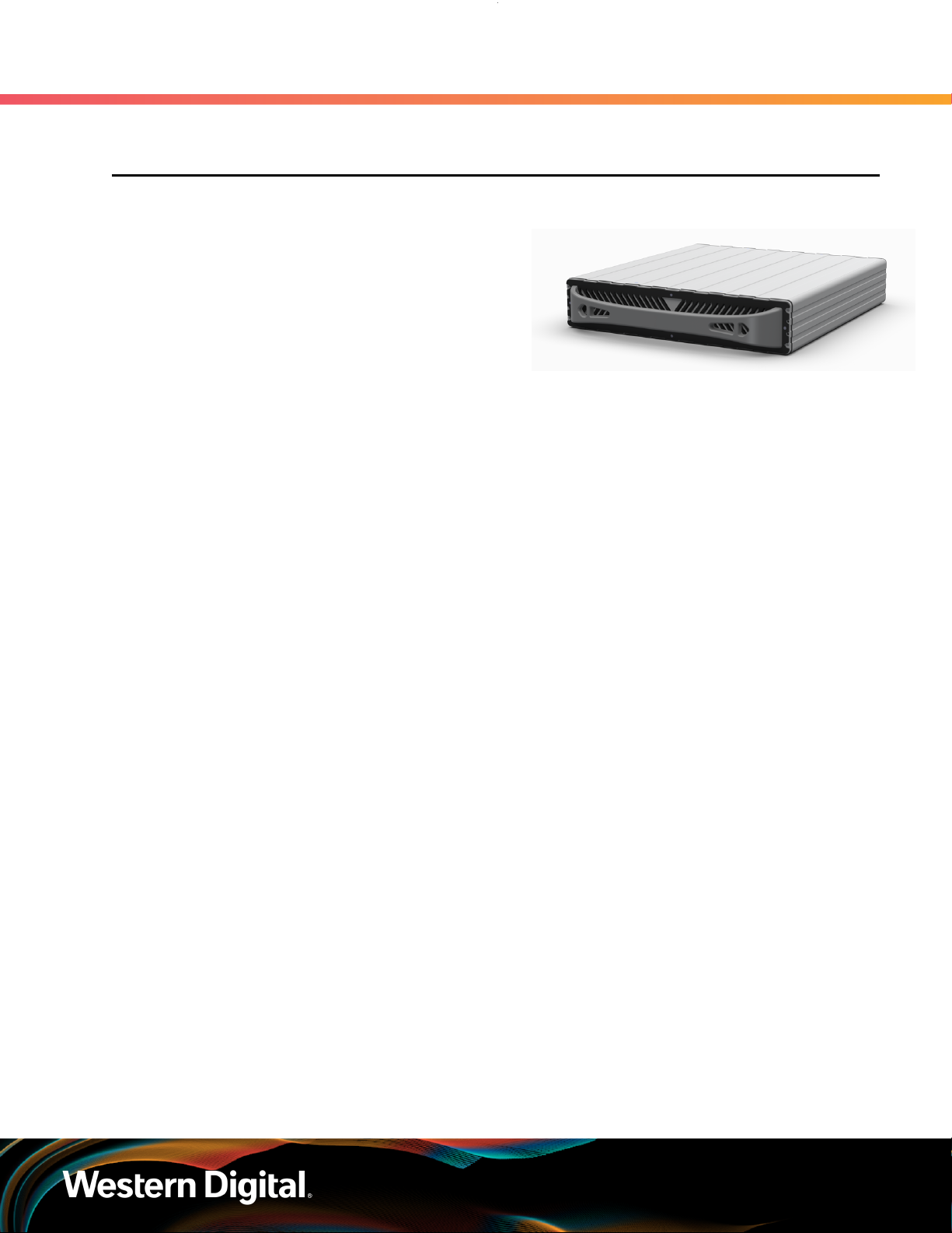
The Ultrastar ™ Edge is a high-performance edge
server that enables organizations to deploy remote
data capture and analytics at the cloud edge. It can
operate in harsh environments such as extremes of
temperature, humidity, dust, shock, and vibration.
The faster processing close to where the data is
generated reduces the latency associated with
sending data from a remote location to the core for
processing which enables faster decision making.
The Ultrastar ™ Edge can be transported using either the Ruggedized Transit Case or Commercial Transit
Case. The system may also be installed into a datacenter rack using optional rack mounted rails.1
Data Ingest & Storage
The Ultrastar ™ Edge provides
a PCIe Gen3 connection to
each of its drives. Utilizing eight
Western Digital Ultrastar DC
SN640 NVMe™ SSDs for a total
raw data storage capacity of
61.44TB 2. Combining high-speed
ingest using the 100GbE QSFP28
Ethernet connection with high-
capacity storage, the Ultrastar ™
Edge is designed for fast, efficient
performance. The built-in GPU
allows for on-board distributed
computing and multi-precision
performance for deep learning
and machine learning.
Security
The Ultrastar ™ Edge contains
multiple security features
designed to ensure the safety of
user data, including an onboard
TPM 2.0 module to help secure
data against intrusion during
ingest. With no external USB or
VGA connections, the Ultrastar
™ Edge's limited external
connectivity is designed to
help prevent unauthorized
access to the data stored on the
enclosure. In addition, the single-
piece aluminum case and bezel
screws provide a tamper-evident
barrier to the enclosure's internal
components.
Portability
The Ultrastar ™ Edge fits within
a standard 19 in. rack on an L-
bracket or shelf or on a table top.
With a maximum weight of 15.2
kg / 33.6 lbs. and an integrated
handle, the enclosure is designed
to be maneuvered by a single
individual during operation. The
Ultrastar ™ Edge also has the
option to be installed into and
operate within a Ruggedized
Transit Case. In addition, the
3U Ruggedized Transit Case
contains EMI filters to protect the
system from electromagnetic
interference. Another option for
Ultrastar ™ Edge transportation is
the Commercial Transit Case.
• 61.44TB max data storage
capacity
• Dual Cascade Lake processor
design with Lewisburg PCH - 2x
6230T 20C 2.1GHz 125W CPUs
• Eight Western Digital Ultrastar DC
SN640 NVMe™ SSDs
• Eight 64GB RDIMMs - 512GB DDR4
ECC DRAM
• Two Western Digital SN720 M.2
SSD boot drives - 2x 1TB NVMe
• Two Broadcom® 9400-16i HBAs
• One dual port Mellanox®
MCX516A-CCAT 100GbE QSFP28
adapter
• Two embedded 10GBaseT RJ45
connections
• One NVIDIA Tesla T4 GPU
• One Serial console port via a DTE
DB-9 connector
• One 850W CRPS PSU - C14
receptacle, 100 - 240VAC
1. Equipment for use in locations where children not likely to be present.
2

User Guide 1. Overview
1.1 Ultrastar ™ Edge Transport Appliance Description
1.1.1 Technical Features
High Speed Data Ingest
The Ultrastar ™ Edge leverages the speed of Ultrastar DC
SN640 NVMe SSDs and a high-speed storage interface to
perform high-speed data ingest. Moving large amounts of data
securely with the Ultrastar ™ Edge can be significantly faster
than with the typical 10GbE network interfaces found in other
data transfer appliances. For instance, the Ultrastar ™ Edge can
ingest 61.44TB of data using two 100GbE connections.
•8 Ultrastar DC SN640 NVMe SSDs
•PCIe Gen3 interface, 2x 100GbE QSFP28 Ethernet
connection
TPM 2.0
The Trusted Platform Module (TPM) 2.0 is a small chip,
providing hardware-based security features that track and
monitor state changes in the system and verify data against
digital signatures stored in the module itself. This provides
a hardware data verification capability that is central to the
security features of the platform. The module allows a user to
establish platform authentication and attestation to ensure a
safer computing environment without physically manipulating
the TPM 2.0 module itself. Coupling this feature with the tamper
evident design means that data intrusion on anything but
internal hardware is unlikely, and the internal hardware cannot
be accessed without leaving positive tamper evidence behind.
•Hardware based data security
3

User Guide 1. Overview
1.1 Ultrastar ™ Edge Transport Appliance Description
Tamper-Evident Design
The Ultrastar ™ Edge has been designed to be tamper-evident.
Any method to physically access the platform is limited by the
design of the outer bezel, aluminum outer shell, and internal
physical construction. Any method that might be used to
access the internal compartment of the platform will be evident
by the damage required to access it. The front bezel screws
are tamper evident and any attempt to pry away the bezel will
result in damage that will be evident upon inspection. This
adds a layer of security that addresses the unique complexities
of physically transporting critical data.
•Front screws-holes covered with tamper evident labels
•Single-piece aluminum body cannot be accessed without
significant force
Portability
The Ultrastar ™ Edge is designed to be portable. With a built
in handle and single-piece aluminum outer shell construction,
the platform can be deployed in many situations. It can be
stored inside a server rack on a shelf style support system, on
a bench or cart, or anywhere that power and connectivity can
be achieved safely. After a successful data transfer, the platform
can be quickly shut down, disconnected, and moved with ease
to wherever the data will be ingested.
•Comfortable handle design
•No protruding components
•Lightweight aluminum construction
4

User Guide 1. Overview
1.2 Electrical Specification
Table 2: Electrical Specifications
Specification Value
Max Power Consumption 850W
Input Voltage 100 - 240VAC, auto-ranging
PSU Connector Type C14
Inrush Current Maximum AC line inrush current will not exceed 40A
peak, for up to one-quarter of the AC cycle.
PSU Efficiency 80 PLUS Platinum
1.3 Environmental Specification
Table 3: Environmental Specifications
Specification Non-Operational Operational
-20°C to 63°C 0° to 43°C3
Temperature w/ Data: -5°C to 40°C w/ Data: 0° to 43°C
Temperature Gradient 20°C per hour max 20°C per hour max
Data Center: 1°C per
300m above 3000m
Temperature De-rating 1°C per 300m above 3000m
MIL-STD: AECTP-230 Leaflet 2311/2
Relative Humidity 8-85% Non-Condensing 8-85% Non-Condensing
Relative Humidity
Gradient 30% per hour maximum 30% per hour maximum
Altitude 0 m to 12,192 m / 0 ft to 40,000 ft 0 m to 3,000 m / 0 ft to 9,843 ft
Cooling N/A 4 Fan Modules
Information about Temperature Specifications
The storage and transportation temperature of a loaded system (defined as user data stored on the system,
consuming more than 10% of PE cycles) is limited by the Ultrastar SN640 NVMe SSDs to no less than -5°C,
and no more than 40°C, to preserve data integrity. A system without data may be subjected to more
extreme temperature ranges. This will serve as the minimum and maximum allowable storage and transport
temperature for Ultrastar ™ Edge.
1.4 Mechanical Specification
3. The compute base ( A2U24-S ) when used by itself is certified for safety to 35°C.
5

User Guide 1. Overview
1.5 System Specification
Table 4: Mechanical Specifications
Specification Value
System Weight 15.2 kg / 33.6 lbs.
System Dimensions W: 432.8 mm x L: 504 mm x H: 88.1 mm
/ W: 17.03 in. x L: 19.84 in. x H: 3.46 in.
Required Rack Depth 508 mm (20 in.) of usable rack space, door to door
Required Rack Width 483 mm (19 in.) with 465mm (18.31in.) ± 1.5mm
nominal hole spacing. See EIA-310 Rack Standard
Rack Units (U) 2U
Adjustable Rail Spacing 711.2 mm – 914.4 mm / 28 in. – 36 in.
1.5 System Specification
Table 5: System Specifications
Specification Value
Data Transfer Rate PCIe Gen3
Max Raw Data Storage Capacity 61.44TB using Western Digital Ultrastar DC SN640 NVMe SSDs
Drives 8x Western Digital Ultrastar DC
SN640 NVMe SSDs
Boot Drives 2x Western Digital SN720 M.2 SSDs 1TB
CPUs 2x Cascade Lake processor design with
Lewisburg PCH, 2.10GHz, 20 C, 125W TDP
Memory 512GB DDR4 Installed (8x 64GB DIMMs)
I/O Dual 10GBase-T Embedded
Dual 100G QSFP28
Management IPMI 2.0 system management over RJ45
Cooling 4x 60mm fans, fixed
1.6 Ruggedized Transit Case MIL-STDs
The Ruggedized Transit Case is supported by MIL-STD level testing. The following table lists the qualified
MIL-STDs.
Table 6: Ruggedized Transit Case MIL-STDs
Number Title
MIL-STD-461G CE102 Radiated & Conducted Emissions & Susceptibility for Army Ground
MIL-STD-461G CE102 Conducted Emissions, Radio Frequency Potentials, Power Leads
MIL-STD-461G CS101 Conducted Susceptibility, Power leads
6

User Guide 1. Overview
1.6 Ruggedized Transit Case MIL-STDs
Number Title
MIL-STD-461G CS114 Conducted susceptibility - Bulk Cable Injection
MIL-STD-461G CS115 Conducted Susceptibility - Bulk Cable Injection, Impulse Excitation
MIL-STD-461G CS116 Conducted Susceptibility, Damped Sinusoidal
Transients, Cables and power leads
MIL-STD-461G CS118 Conducted susceptibility, Personnel Borne ESD
MIL-STD-461G RE102 Radiated Emissions, Electric field
MIL-STD-461G RS103 Radiated susceptibility - Electric field
MIL-STD-1472G Lifting Limits
MIL-STD-810G CHG-1, Method
501.6, Procedure I, II High Temperature Storage and Operation, basic hot
MIL-STD-810G CHG-1, Method
516.7, Procedure I Operating unpackaged shock
MIL-STD-810G CHG-1, Method
516.7, Procedure II Non-operating packaged shock
MIL-STD-810G CHG-1, Method
516.7, Procedure IV Non-operating packaged drop
MIL-STD-810G CHG-1, Method
514.7, Procedure III Large assembly (trucks and trailers) transportation
7

User Guide 1. Overview
1.7 Ultrastar ™ Edge Physical Design
This section shows the dimensions and layout of the primary physical features of the Ultrastar ™ Edge.
Figure 10: Ultrastar ™ Edge Dimensions
Figure 11: Ultrastar ™ Edge Primary External Features
Ultrastar ™ Edge Rear Ports and Features
8

User Guide 1. Overview
1.7 Ultrastar ™ Edge Physical Design
Power
Receptacle
2x QSFP28
Ports
Power Switch
2x RJ45 DB-9 Serial
Console Port
1.7.1 Rear IO LEDs
The Ultrastar ™ Edge has a number of LEDs at the rear exterior of the enclosure that display various system
statuses.
Rear IO LED Locations
6
1
2
2
3
3
4
5
9

User Guide 1. Overview
1.7 Ultrastar ™ Edge Physical Design
Table 7: Rear LED Identification
# LED Name Color Behavior
1Power Supply
Fault/Output Status
Green/
Amber
Solid Green – On and providing power to the system
Blink Green @ 1 Hz – AC Present/Only 5VSB on
(power supply off)
Solid Amber - Fault on power supply
210GBase-T RJ45 Ethernet
Connectors Link/Activity Green
Link/Activity:
Solid – LAN link is established
Blink – Transmitting or receiving activity
Off – LAN link is not established
310GBase-T RJ45 Ethernet
Connectors Speed
Green/
Amber
Speed:
Green – Highest supported data rate (10Gbps)
Amber – Mid-range supported data rate (1Gbps)
Off – Lowest supported data rate (100Mbps)
4 Identification Blue Solid – System ID/locate/BMC boot status
5 System Status Green/
Amber
Green solid – System is operational
Amber blink @ 1 Hz – Warning: system failure
6 NIC Link/Activity Green/
Amber
Green Solid – LAN link is established
Green blink – Transmitting or receiving activity
Amber blink @ 4Hz - Indicates a problem with the
link
Off – Link is not established
10

User Guide 1. Overview
1.8 Supported Operating Systems
1.7.2 System Level Block Diagram
The system block diagram for the Ultrastar ™ Edge is a conceptual depiction of the communication and
power relationships between major components within the system.
Figure 14: System Block Diagram
Table 8: Port Accessibility
Externally Accessible Not Externally Accessible
Serial Console BMC Management (RJ45)
RJ45 Ports VGA
QSFP28 Ports USB 2.0
Power Override Switch USB 3.0
1.8 Supported Operating Systems
The following table lists the operating systems tested on the Ultrastar ™ Edge.
11

User Guide 1. Overview
1.9 Restrictions and Limitations
Operating System Version
Oracle Linux® 7.7
1.9 Restrictions and Limitations
The Ultrastar ™ Edge has the following restrictions and limitations on functionality:
•The Western Digital SN720 M.2 SSDs contained within the Ultrastar ™ Edge cannot be setup in a
Hardware RAID configuration. This is a limitation of the Intel Motherboard.
1.10 Supported SKUs
The following table lists the versions of Western Digital product that are supported by this document.
Table 10: System Configurations
System Volume Part Number
Ultrastar ™ Edge SN640
B6230T-5-2-2I-1D-CM nTAA PCIe RI-0.8DW/D ISE - CRPS 61.44TB 1ES2114
Ultrastar ™ Edge SN640
B6230T-5-2-2I-1D RG nTAA PCIe RI-0.8DW/D ISE - CRPS 61.44TB 1ES2115
Table 11: Rail
Component Part Number
Rail Kit 1EX2861
1.11 List of CRUs
Table 12: List of Replaceable Components
Part
Number Component Package Dimensions Weight
1EX2861 Rail Kit W: 432.8 mm x L: 504 mm x H: 88.1 mm
/ W: 17.03 in. x L: 19.84 in. x H: 3.46 in.
5.26 kg /
11.6 lbs
1EX2859
Power Cord 1.8m
NEMA 5-15P to
IEC-320-C13 14AWG
W: 330.2 mm x L: 254 mm x H: 101.6 mm
/ W: 13 in x L: 10 in x H: 4 in
0.85 kg /
1.88 lbs
1EX2857 USB to Serial
Adapter Cable 1.52m
W: 330.2 mm x L: 254 mm x H: 101.6 mm
/ W: 13 in x L: 10 in x H: 4 in
0.26 kg /
0.59 lbs
1EX2855 Packaging for
Ruggedized Transit Case
W: 968.2 mm x L: 628.6 mm x H: 304.8 mm
/ W: 38.12 in x L: 24.75 in x H: 12 in
3.6 kg /
8 lbs
1EX2856 Packaging for
Ultrastar ™ Edge
W: 608.3 mm x L: 533.4 mm x H: 266.7 mm
/ W: 23.95 in x L: 21 in x H: 10.5 in
2.97 kg /
6.55 lbs
12

User Guide 1. Overview
1.11 List of CRUs
Part
Number Component Package Dimensions Weight
1EX2858 Packaging for
Commercial Transit Case
W: 673.1 mm x L: 622.3 mm x H: 266.7 mm
/ W: 26.5 in x L: 24.5 in x H: 10.5 in
1.95 kg /
4.3 lbs
13
This manual suits for next models
1
Table of contents
Other Western Digital Controllers manuals
Popular Controllers manuals by other brands

Mitsubishi Electric
Mitsubishi Electric MELSEC-F FX-USB-AW user manual

DROPSA
DROPSA ADVANCED LUBRICATION CONTROLLER INSTRUCTION AND PRODUCT DATA SHEET

Eurotech
Eurotech Helios Platform Hardware reference manual

Emerson
Emerson Fisher D4 instruction manual

Carel
Carel WS01H02M20 quick start guide

Megmeet
Megmeet MC5000 Series User quick reference manual

Hyundai
Hyundai HYU-AC-NCDCCF00 1 user manual

Duratrax
Duratrax ESC 1000 operating instructions

Hyperkin
Hyperkin CADETP REMIUM instruction manual

Spa-Quip
Spa-Quip SP601 Installation & service manual

GREISINGER
GREISINGER GIR 230 Pt1000 / DIF Manual for connection and operation

STORK TRONIC
STORK TRONIC ST501-JX1TA manual