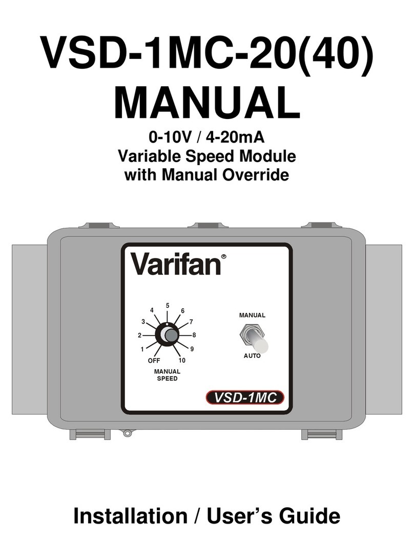
Varifan VSD-1C User manual

VSD-1C
MANUAL
0-10V / 4-20mA
Variable Speed Module
Installation / User’s Guide
®
Varifan

VSD-1C
Page 2
This guide will inform the electrician on proper wiring and installation procedures
and, will also inform the user on how to use the VSD-1C module.
The manufacturer recommends that the following installation instructions be
followed to as closely as possible, and that all work be performed by a certified
electrician. Failure to do so may void the warranty.
Description
The VSD-1C module is designed to control a variable speed fan according to a 0-
10 V or a 4-20 mA signal. The module operates on 115/230V and 50/60Hz.
The VSD-1C comes in a PVC non-corrosive enclosure that is protected from dust
and humidity. The VSD-1C is covered by a complete two-year warranty.
Unpacking
Unpack the VSD-1C module and inspect contents for damage. Should the
contents appear to be damaged, contact your local distributor to return the
equipment.
The package should contain the following standard items:
1 VSD-1C
1 Installation / User’s Guide
Mounting hardware required
This is the list of the mounting hardware needed, which is not included with the
product:
2 conductors wire, non-twisted, AWG #22
Screws (to mount the module on the wall)
Screwdriver
Soldering iron kit or approved sealed connectors

VSD-1C
Page 3
General installation guidelines
-It is recommended to install the unit in a hallway to limit the VSD-1C exposure to
noxious gases.
-In order to avoid condensation problems inside the VSD-1C, it is recommended to
install the module on an inside wall. If it is not possible, use spacers to have an air
gap between the wall and the module.
-The VSD-1C should be installed in easy-access location but away from damaging
elements (heat, cold, water, direct sunlight…).
-Do not drill the face, the side, the top or the underside of the module.
-Do not install the VSD-1C near high-voltage equipment, power supply or transformer.
Wiring Procedure
1. Open the VSD-1C module enclosure.
2. Verify the technical specifications to know which wire to use.
3. Connect the equipment to the 2 black terminal block identified as FAN as shown
in figure 1.
4. Connect the power source to the 2 black terminal block identified as LINE as
shown in figure 1.
5. Set the JP1 jumper (refer to figure 2 for the location of the jumper) to determine
the correct input type. The two types of input are: 0-20 mA (jumper on the 2 left
pins) and 0-10 Volts (jumper on the 2 right pins)
6. Connect the 0-10 V or the 4-20 mA signal to the 2 green terminal block identified
as INPUT as shown in figure 1.
IMPORTANT: Low-voltage and high-voltage wire must be passed through different
conducts at least 1 foot (30 cm) apart. If low-voltage and high-voltage conduits must
be crossed, the crossing must be at a 90-degree angle.
7. Make sure that the voltage selector switch is set to the correct voltage before
powering up the VSD-1C (refer to figure 2 for the location of the voltage selector
switch).
8. Power up the VSD-1C module. Verify that the module operates correctly.
9. Close the VSD-1C enclosure. Don’t forget to put a security screw or a padlock.

VSD-1C
Page 4
Figure 1: Wiring Diagram
WARNING!
To avoid electric shock, disconnect power source prior to
installation or troubleshooting.
Make sure that the voltage selector switch is set to the correct
voltage before powering up the module.
0-10 Volts or 4-20 mA
INPUT SIGNAL
230V
LINE
VOLTAGE
115/230
VAC

VSD-1C
Page 5
Using the VSD-1C
With the VSD-1C you can control a variable fan according to a 0-10 Volts or 4-20 mA
input signal. Refer to figure 2 for the location of the different switches, jumpers and
selectors of the module.
Figure 2: Electronic Board and Component Location
15 A/250V
230V
FAN LINE
115/230V
INPUT
1341 B
- +
ON
OFF
1 2
MIN. SPEED
-+
0-20mA
0-10V
JP1
1. Minimum Speed Potentiometer
This potentiometer is used to adjust the Minimum Speed of the fan. This will be
the minimum speed when the input signal is at its minimum value.
2. Dip Switches (Input Range and Shutoff 5%)
Dip Switch 1 is used to select the Input Range (ON = 2-10 Volts / 4-20 mA, OFF
= 0-10 Volts / 0-20 mA).
Dip Switch 2 is used to adjust the output behavior when the input is below 5% of
its total range (ON = Shutoff, OFF = Runs continuously at Minimum Speed).
3. Input Type Jumper
This jumper is used to select which input type is used. Two types of input can be
used which are: 0-10 Volts (jumper on the 2 left pins) and 0-20 mA (jumper on
the 2 right pins).
[2]
[
1
]
[
3
]

VSD-1C
Page 6
The VSD-1C module uses a 0-10 Volts or a 4-20 mA signal to make a fan modulate.
User can adjust the fan Minimum Speed with the potentiometer located inside the
module box on the electronic board (refer to figure 2). That Minimum Speed
potentiometer is used to adjust the speed when the input is at its lowest value.
User can also set how the fan will operates when the input signal is at or below 5%
of its total range. Refer to the logic diagrams at figure 3 to know the exact values and
behavior of the different switches configurations. The fan can either continue to run
at Minimum Speed (Shutoff 5% set to OFF) when the input has reach its minimum
value or can stop when the input reach 5% of its total range (Shutoff 5% set to ON).
With the Shutoff at 5% switch set to ON, a differential is applied in order to avoid
equipment wear. Refer to figure 3 for the exact value of the differential. Also refer to
figure 2 for the location of the Shutoff 5% switch.
Another switch also located on the electronic board will select if the input is a 0-10
Volts (0-20 mA) or a 2-10 Volts (4-20 mA) signal. Refer to figure 2 for the location of
the Input Range switch.
Finally, a jumper (JP1) must be set to determine the Input Type used. Two types are
available which are: 0-10 Volts (jumper on the 2 left pins) and 0-20 mA (jumper on
the 2 right pins). Refer to figure 2 for the location of the Input Type jumper.
Here is a description of the VSD-1C operation:
- If the Shutoff 5% switch is set to OFF, the fan will run continuously at its
Minimum Speed when the input reads it lowest value. If the Shutoff 5% switch
is set to ON, the fan will stop when the input is at or below 5% of its total range. A
differential is applied to the 5% value. Refer to figure 3 for the exact value of the
differential.
-If the input reads above its minimum value (or 5% if the Shutoff 5% switch is set
to ON), the fan will modulate from its Minimum Speed to 100% of its maximum
speed. The full speed will be reached when the input reads 10 Volts or 20 mA.

VSD-1C
Page 7
Figure 3: Logic Diagrams
Switch 1 = OFF (0-10 Volts or 0-20 mA)
Switch 2 = OFF (No shutoff at 5%)
Fan Speed
100%
Minimum
Speed
10 Volts
or 20 mA
Input
0
Switch 1 = ON (2-10 Volts or 4-20 mA)
Switch 2 = OFF (No shutoff at 5%)
Fan Speed
100%
Minimum
Speed
10 Volts
or 20 mA
Input
0 2 Volts
or 4 mA

VSD-1C
Page 8
Switch 1 = OFF (0-10 Volts or 0-20 mA)
Switch 2 = ON (Shutoff at 5%)
Fan Speed
100%
Minimum
Speed
10 Volts
or 20 mA
Input
00.7 Volts
or 1.4 mA
0.5 Volts
or 1 mA
Switch 1 = ON (2-10 Volts or 4-20 mA)
Switch 2 = ON (Shutoff at 5%)
Fan Speed
100%
Minimum
Speed
10 Volts
or 20 mA
Input
02.7 Volts
or 5.4 mA
2.5 Volts
or 5 mA

VSD-1C
Page 9
Specifications
DESCRIPTION VALUE
Storage temperature -4°F to 131°F (-20°C to 55°C)
Operating temperature 32°F to 113°F (0°C to 45°C)
Humidity 90% maximum Non-condensing
Weight 1,2 lb (0,5 kg)
Size 5 15/16” x 5 15/16” x 3 9/16” (15 cm x 15 cm x
10 cm)
Protection index IP 66
Warranty 2 years
POWER SUPPLY
Operational voltage range (SW1 @ 115V) 92 to 125 VAC
Operational voltage range (SW1 @ 230V) 184 to 250 VAC
Operational frequency range 45 to 65 Hz
INPUT
Input Range 0-10 Volts or 0-20 mA
Maximum wire length 500 feet (150 m)
Recommended wires 2 conductors wire, non-twisted, AWG #22
VARIABLE OUTPUT
Maximum Allowable Current (Fuse value) 15 A, 250 VAC
Recommended maximum current for fans 12 FLA
Minimum load 300 mA @ 230 VAC

VSD-1C
Page 10
Limited Warranty
The manufactured equipment and supplied components have gone through
rigorous inspection to assure optimal quality of product and reliability. Individual
controls are factory tested under load, however the possibility of equipment
failure and/or malfunction may still exist.
For service, contact your local retailer or supplier. The warranty period shall be
for two years from manufacturing date. Proof of purchase is required for warranty
validation.
In all cases, the warranty shall apply only to defects in workmanship and
specifically exclude any damage caused by over-voltage, short circuit, misuse,
acts of vandalism, lightning, fortuitous events, acts of God, flood, fire, hail or any
other natural disaster. Any unauthorized work, modification or repair on this
product automatically voids the warranty and disclaims the manufacturer from all
responsibility.
The manufacturer assumes only those obligations set forth herein, excluding all
other warranties or obligations. This warranty stipulates that in all cases the
manufacturer shall be liable only for the supply of replacement parts or goods
and shall not be liable for any personal injury, damages, loss of profits,
interrupted operations, fines for infringement of the law or damages to the
production of the PURCHASER and the PURCHASER shall take up the defence
and hold the manufacturer faultless regarding any legal or extra legal
proceedings, notice, or claim by the customer or by a third party, and regarding
any legal and extra legal expenses and fees brought forward on by such
damages.

VSD-1C VER : 2.0
October 20, 2014
Table of contents
Other Varifan Control Unit manuals