Hermann Sonda esterna Radio Reference manual
Sonda esterna Radio
Istruzioni per
l’installazione


0020105669_02 - 08/10 - Hermann - 1 -
1
EW
S
N
≥ 2,5 m
1
INSTALLAZIONE
IT
Luogo di montaggio
1 Sonda esterna
Montare la sonda esterna in luogo
parzialmente protetto, al riparo dalla
pioggia dal vento e dalle correnti
d’aria. Non deve essere esposta ai
raggi diretti del sole.
INSTALLATION
GB
Mounting location
1 Outdoor sensor
Install the sensor so that it is
sheltered from wind, draughts and
direct exposure to the sun.

0020105669_02 - 08/10 - Hermann
- 2 -
6A
B
2
3
1
23
4
ON
5
IT
A Temperatura mandata
riscaldamento
B Temperatura esterna
Regolazione curva
riscaldamento
1 Radiatori sottodimensionati
2 Radiatori standard
3 Radiatori bassa temperatura
o pavimenti radianti
GB
$ +HDWLQJÀRZWHPSHUDWXUH
B External temperature
Setting the heating curve
2OGHUSURSHUWLHVZLWK
radiators
6WDQGDUGPRGHUQKRXVHZLWK
radiators
3 Highly insulated modern
KRXVHZLWKORZWHPSHUDWXUH
UDGLDWRUVRUXQGHUÀRRU
heating
0020105669_02 - 08/10 - Hermann - 3 -
IT
IT &RQ¿JXUD]LRQHGHOODVRQGD
esterna
INTRODUZIONE
La sonda esterna permette di misurare
e di trasmettere la temperatura esterna
al sistema di riscaldamento. Il sistema
di riscaldamento regola la temperatura
dell’acqua di riscaldamento in funzione
della temperatura esterna.
L’alimentazione elettrica è fornita da una
cellula fotovoltaica. La sonda esterna non
ha batterie da sostituire.
1 Riciclaggio
iIl riciclaggio dell’imballaggio
deve essere effettuato da un
WHFQLFRTXDOL¿FDWR
1.1 Apparecchio
La sonda esterna deve essere smaltita
adeguatamente. Provvedere a smaltire
la sonda dismessa e i suoi componenti
differenziandoli opportunamente secondo
le previste normative Nazionali e locali.
4XHVWRVLPERORVLJQL¿FD
che questo apparecchio
non deve essere gettato
DVVLHPHDLUL¿XWLGRPHVWLFL
ma è oggetto di una raccolta
selettiva dovuta al suo valore,
al riutilizzo o al riciclaggio.
Il riciclaggio deve essere
effettuato da un tecnico
TXDOL¿FDWR
iRispettando queste disposizioni
fate un gesto per l’ambiente
e contribuite a preservare le
risorse naturali e a proteggere
ODVDOXWHXPDQD
1.2 Imballaggio
Smaltire il materiale d’imballaggio
secondo le previste normative nazionali e
locali.
INTRODUZIONE
0020105669_02 - 08/10 - Hermann
- 4 -
IT
Il riconoscimento si effettua
simultaneamente sul ricevitore radio del
termostato ambiente e sulla sonda esterna
di temperatura.
INSTALLAZIONE
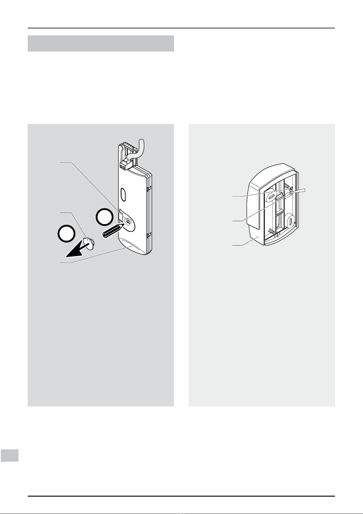
2 Abbinamento (riconoscimento)
La connessione della sonda esterna è
possibile tramite il termostato ambiente
Cronocontrol Radio (attraverso il ricevitore
radio).
sul ricevitore radio +sulla sonda esterna
3
2
1
A
B
ON
1
2
3
Legenda
1 Ricevitore radio
2 Tappo
3 Pulsante di abbinamento
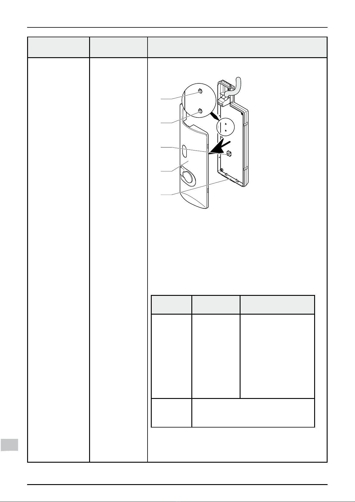
Legenda
1 Sonda esterna di temperatura
2 Pulsante di abbinamento
3 LED verde
Togliere il tappo (2) per accedere al
pulsante di abbinamento (3).
Premere per 10 secondi sul pulsante
di abbinamento (3).
La temperatura esterna appare sul
termostato ambiente entro un massimo
di 30 minuti.
Effettuare una pressione breve sul
pulsante di abbinamento (2) che
si trova dietro la sonda esterna di
temperatura.
Il LED verde (3) lampeggia una volta.
L’abbinamento della sonda esterna è
stato effettuato.
INSTALLAZIONE

0020105669_02 - 08/10 - Hermann - 5 -
IT
3 Regolazioni
Tre parametri devono essere regolati sul
sistema di riscaldamento:
- la curva di riscaldamento,
- la temperatura di mandata
riscaldamento massima,
- la correzione della temperatura esterna.
E’ importante effettuare tutte le regolazioni
sugli apparecchi che compongono il
sistema di riscaldamento:
- il termostato ambiente Cronocontrol
Radio,
- la caldaia.
iLa sonda comunica la
temperatura esterna ogni 10
minuti al termostato ambiente
(attraverso il ricevitore radio)
iSe non c’è più la connessione
con la sonda esterna di
temperatura, il sistema di
ULVFDOGDPHQWRPRGL¿FDOD
regolazione dopo un intervallo
GLJLRUQL
ll termostato ambiente effettua
una regolazione senza
prendere in considerazione la
WHPSHUDWXUDHVWHUQD
3.1 Regolazione della curva di
riscaldamento¿J
Scegliere la curva (valore regolabile
tra 0,2 e 4) che permette di ottenere la
massima temperatura di mandata alla
temperatura esterna minima tipica della
regione in cui la sonda è installata.
iNota: più il rendimento dei
corpi scaldanti è buono, meno
è elevato il valore della curva:
>±@SHULUDGLDWRULEDVVD
temperatura o i pavimenti
radianti,
>§@SHULUDGLDWRULVWDQGDUG
>@SHULUDGLDWRUL
VRWWRGLPHQVLRQDWL
3.2 Regolazione della temperatura di
mandata riscaldamento massima.
Questa funzione disponibile in caldaia
permette di effettuare le regolazioni
della temperatura massima di mandata
riscaldamento (valore regolabile tra 30° C
e 80° C).
Consultare i manuali di installazione
della caldaia.
3.3 Correzione della temperatura
esterna
Questa funzione disponibile sul termostato
DPELHQWHSHUPHWWHGLPRGL¿FDUHOD
temperatura misurata dalla sonda esterna
(di +/- 5° C con un passo di 1° C).
Consultare i manuali di installazione del
termostato ambiente.
INSTALLAZIONE
0020105669_02 - 08/10 - Hermann
- 6 -
IT
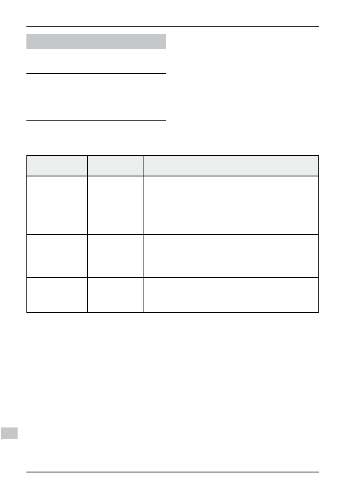
MANUTENZIONE
4 Diagnosi dei guasti
iI guasti descritti in questo
capitolo devono essere trattati
GDXQ7HFQLFRTXDOL¿FDWRHVH
QHFHVVDULRGDOVHUYL]LRSRVW
YHQGLWD
9HUL¿FDUHLPHVVDJJLGLHUURUH
visualizzati sul termostato ambiente.
Stato Causa Soluzione
Il termostato
ambiente non
visualizza la
temperatura
esterna o
visualizza «T° ext.
--».
- Problema di
abbinamento.
- Mancanza di
trasmissione del
segnale radio.
$WWHQGHUHPLQXWLPDVVLPRGRSRO¶DEELQDPHQWRSHUIDU
visualizzare la temperatura esterna.
5LGXUUHOHGLVWDQ]HHJOLRVWDFROLWUDODVRQGDHVWHUQDHLO
sistema di riscaldamento.
Il termostato
ambiente mostra
una temperatura
esterna non
coerente o errata.
- Mancanza di
trasmissione del
segnale radio.
7HVWDUHODTXDOLWjGHOVHJQDOHUDGLRIDUHULIHULPHQWRDO
manuale d’installazione del termostato ambiente).
6HLOULVXOWDWRGHOWHVWq©QXOORªULGXUUHOHGLVWDQ]HHJOL
ostacoli tra la sonda esterna e il sistema di riscaldamento.
Il termostato
ambiente mostra
«errore di
connessione».
- Problema di
abbinamento.
5LSHWHUHODSURFHGXUDGLDEELQDPHQWRWUDODVRQGD
esterna e il ricevitore radio.
5LGXUUHOHGLVWDQ]HHJOLRVWDFROLWUDODVRQGDHVWHUQDHLO
sistema di riscaldamento.
MANUTENZIONE

0020105669_02 - 08/10 - Hermann - 7 -
IT
Stato Causa Soluzione
Il LED verde della
sonda esterna
lampeggia dopo
l’abbinamento.
- Problema di
trasmissione del
segnale radio
con il ricevitore
radio.
5LSHWHUHODSURFHGXUDGLDEELQDPHQWRGHOODVRQGD
esterna.
5
4
3
2
1
Legenda
1 Ricevitore radio
2 Coperchio
3 Pulsante di abbinamento
4 LED rosso
5 LED verde
7RJOLHUHLOFRSHUFKLRSHUDFFHGHUHDOSXOVDQWHGL
abbinamento (3) e ai LED (4) e (5).
9HUL¿FDUHORVWDWRGHL/('YHUGHHURVVRSRVWL
sulla scheda elettronica (1) del ricevitore radio.
Ricevitore
radio
Causa Soluzione
LED verde
spento
e
LED rosso
spento
- Interruzione
della corrente
elettrica
- Cavo di
collegamento
EBUS
difettoso
9HUL¿FDUHFKH
non ci sia una
interruzione della
rete elettrica e che la
caldaia sia collegata
correttamente e in
tensione.
&RQWUROODUHLO
collegamento elettrico
tra il ricevitore radio e
il generatore.
LED rosso
acceso
3UREOHPDQRQULJXDUGDQWHODVRQGD
esterna. Fare riferimento al manuale di
installazione del termostato ambiente.
3UHPHUHSHUVHFRQGLVXOSXOVDQWHGLDEELQDPHQWR
Il LED verde (5) lampeggia per 10 minuti.
La temperatura esterna appare sul termostato ambiente
entro un massimo di 30 minuti.
MANUTENZIONE
0020105669_02 - 08/10 - Hermann
- 8 -
GB
GB &RQ¿JXULQJWKHRXWGRRU
sensor
INTRODUCTION
The outdoor sensor enables the
measurement and transmission of the
outside temperature to the heating
system. The heating system adjusts
the temperature of the heating water
according to the outside temperature.
The power is provided by a photovoltaic
cell. The outdoor sensor does not contain
any batteries to replace.
1 Recycling
iThe recycling of the packaging
PXVWEHGRQHE\WKHTXDOL¿HG
professional who has installed
\RXUDSSOLDQFH
1.1 Appliance
Most of the outdoor sensor is made of
recyclable materials.
This symbol indicates that
this appliance should not
be deposited with common
refuse; it is to be collected
separately for its recovery,
reuse or recycling.
iBy adhering to this directive,
you are helping the
environment and contributing
to the preservation of natural
resources and the protection of
KXPDQKHDOWK
1.2 Packaging
We recommend that you recycle
the packaging of the appliance in a
responsible fashion.
INTRODUCTION

0020105669_02 - 08/10 - Hermann - 9 -
GB
INSTALLATION
2 Pairing (detection)
It is possible to connect the outdoor
sensor with the Cronocontrol Radio
programmable room thermostat (via the
radio receiver).
via radio receiver +the outdoor sensor
3
2
1
A
B
ON
1
2
3
Legend
1 Radio receiver
2 Plug
3 Pairing button
Legend
1 Outdoor temperature sensor
2 Pairing button
3 Green LED
Remove the plug (2) to access the
pairing button (3).
Press the pairing button (3) for 10
seconds.
The outside temperature appears on the
room thermostat within 30 minutes max.
Press the pairing button (2), which
is on the back of the outdoor
temperature sensor.
7KHJUHHQ/('ZLOOÀDVKRQFH7KH
outdoor sensor is then paired.
The action is carried out simultaneously
on both the radio receiver of the room
thermostat and the outdoor temperature
sensor.
INSTALLATION

0020105669_02 - 08/10 - Hermann
- 10 -
GB
3 Settings
There are three parameters to set in the
heating system:
- the heating curve,
-WKHPD[LPXPÀRZKHDWLQJWHPSHUDWXUH
- the correction of the outdoor
temperature.
It is important that all the settings are
made on all the component parts of the
heating system:
- the Cronocontrol Radio programmable
room thermostat,
- the boiler.
iThe outdoor sensor sends data
on the outside temperature to
the room thermostat (via the
radio receiver) or the control
XQLWHYHU\PLQXWHV
iShould the connection to the
outdoor sensor be interrupted,
the regulation of the system
ZLOOEHPRGL¿HGDIWHUDSHULRG
RIGD\V
The room thermostat will
PDNHPRGL¿FDWLRQVZLWKRXW
taking into account the outdoor
WHPSHUDWXUHUHDGLQJ
3.1 Adjustment of the heating curve
¿J
Choose the curve(value adjustable
between 0.2 and 4), which allows you
WRREWDLQWKHPD[LPXPKHDWLQJÀRZ
temperature for the usual minimum
outdoor temperature for the region in
which the sensor is installed.
iComment: The lower the heat
loss of the house, the lower
the value of the heat curve
required:
>@KLJKO\LQVXODWHG
modern house with low
temperature radiators or
XQGHUÀRRUKHDWLQJ
>§@VWDQGDUGPRGHUQKRXVH
with radiators,
>@ROGHUSURSHUWLHVZLWK
UDGLDWRUV
3.2 6HWWLQJWKHPD[LPXPÀRZKHDWLQJ
temperature.
This function, available on the control unit
and on the boiler, enables the maximum
heating output temperature to be set
(value adjustable between 30 °C
and 80 °C).
Consult the instruction manual of the
boiler.
3.3 Outdoor temperature correction
This function, available on the room
thermostat, enables the temperature
measured by the outdoor sensor to be
corrected (+/- 5 °C at 1 °C intervals).
Consult the Cronocontrol Radio
instruction manual.
INSTALLATION
0020105669_02 - 08/10 - Hermann - 11 -
GB
MAINTENANCE
4 Fault diagnosis
iFaults described in this
chapter should be carried out
E\DTXDOL¿HGHQJLQHHUDQG
if needed by the After Sales
6HUYLFH
In the event of a problem:
Check the error messages in the
display zone for the room thermostat.
State Cause Solution
The room
thermostat does
not display
the external
temperature or
displays «T° ext.
--».
- Pairing fault.
- Radio signal
transmission
fault.
:DLWDPD[LPXPRIPLQXWHVDIWHUSDLULQJIRUWKH
external temperature to be displayed.
5HGXFHWKHGLVWDQFHDQGWKHREVWDFOHVEHWZHHQWKH
outdoor sensor and the heating systems.
The room
thermostat
displays
an external
temperature that
is inconsistent or
erroneous.
- Radio signal
transmission
fault.
7HVWWKHTXDOLW\RIWKHUDGLRVLJQDOVHHWKHLQVWDOODWLRQ
notice for the room thermostat).
,IWKHUHVXOWRIWKHWHVWLV©FRQQHFWLRQHUURUªUHGXFHWKH
distance and the obstacles between the outdoor sensor
and the heating system.
The room
thermostat
displays
«connection
error».
- Pairing fault. 5HSHUIRUPWKHSDLULQJSURFHGXUHEHWZHHQWKHRXWGRRU
sensor and the radio receiver.
5HGXFHWKHGLVWDQFHDQGWKHREVWDFOHVEHWZHHQWKH
outdoor sensor and the heating systems.
MAINTENANCE
0020105669_02 - 08/10 - Hermann
- 12 -
GB
State Cause Solution
The outdoor
sensor’s green
/('ÀDVKHVDIWHU
pairing.
- Fault in the
transmission of
the radio signal
between the
outdoor sensor
and the radio
receiver.
5HSHUIRUPWKHSDLULQJSURFHGXUHZLWKWKHRXWGRRU
sensor.
5
4
3
2
1
Legend
1 Radio receiver
2 Cover
3 Pairing button
4 Red LED
5 Green LED
5HPRYHWKHFRYHULQRUGHUWRDFFHVVWKHSDLULQJ
button (3) and the LEDs (4) and (5).
&KHFNWKHVWDWXVRIWKH/('VJUHHQDQGUHG
located on the radio receiver’s electronic board (1)).
Radio
receiver
Cause Solution
Green LED
off
and
Red LED
off
- Power cut
- Defective
EBUS
connection
cable
&KHFNWKDWWKHUHLV
no power cut in the
electrical network and
that the appliance is
correctly connected
and switched on.
&KHFNWKHHOHFWULFDO
connection between
the radio receiver and
the appliance.
Red LED
lit
)DXOWWKDWGRHVQRWFRQFHUQWKH
outdoor sensor. See the installation
manual for the Cronocontrol Radio.
3UHVVWKHSDLULQJEXWWRQIRUVHFRQGV
7KHJUHHQ/('ZLOOÀDVKIRUPLQXWHV
The outside temperature appears on the room thermostat
within 30 minutes max.
MAINTENANCE


0020105669_02-08/10
www.hermann.it
Servizio assistenza Post-Vendita: Tel.
0523 512611
Fax. 0523 519028
Centralino:
Tel.0523 512511
Fax. 0523 510359
HERMANN SRL
Via Salvo D’Acquisto
29010 Pontenure (Piacenza)
E-mail: herm[email protected]
&RQULVHUYDGLPRGL¿FKHWHFQLFKH
Table of contents
Languages:


