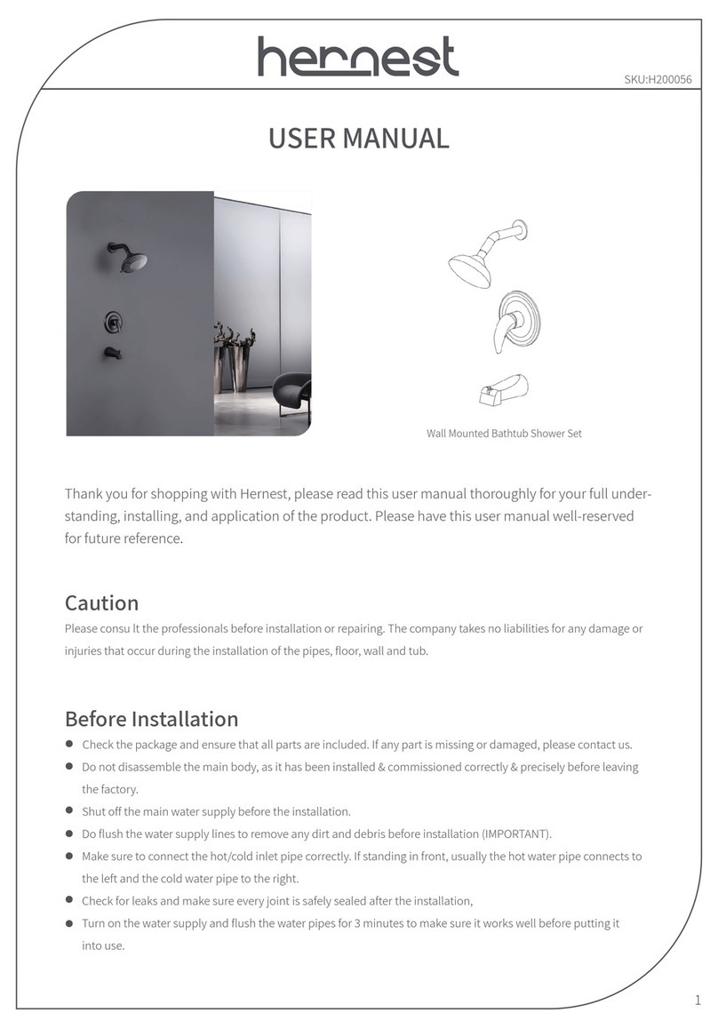
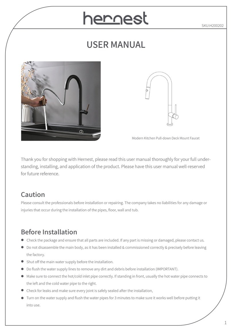
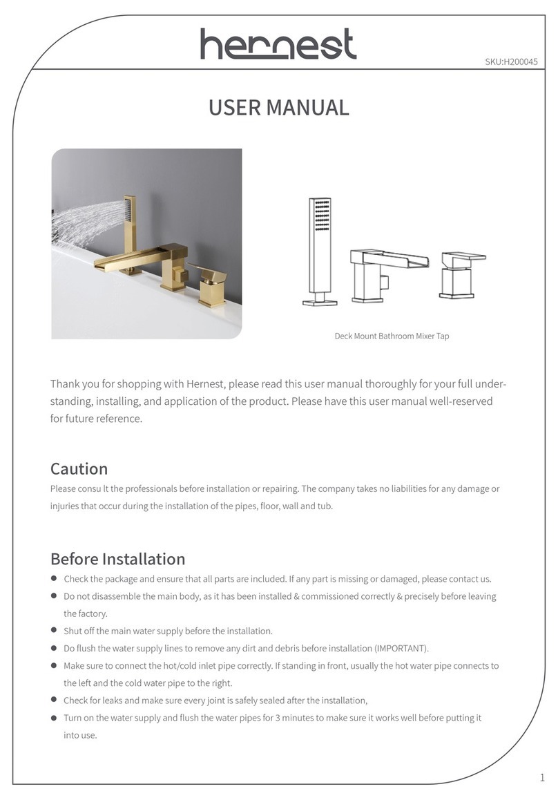
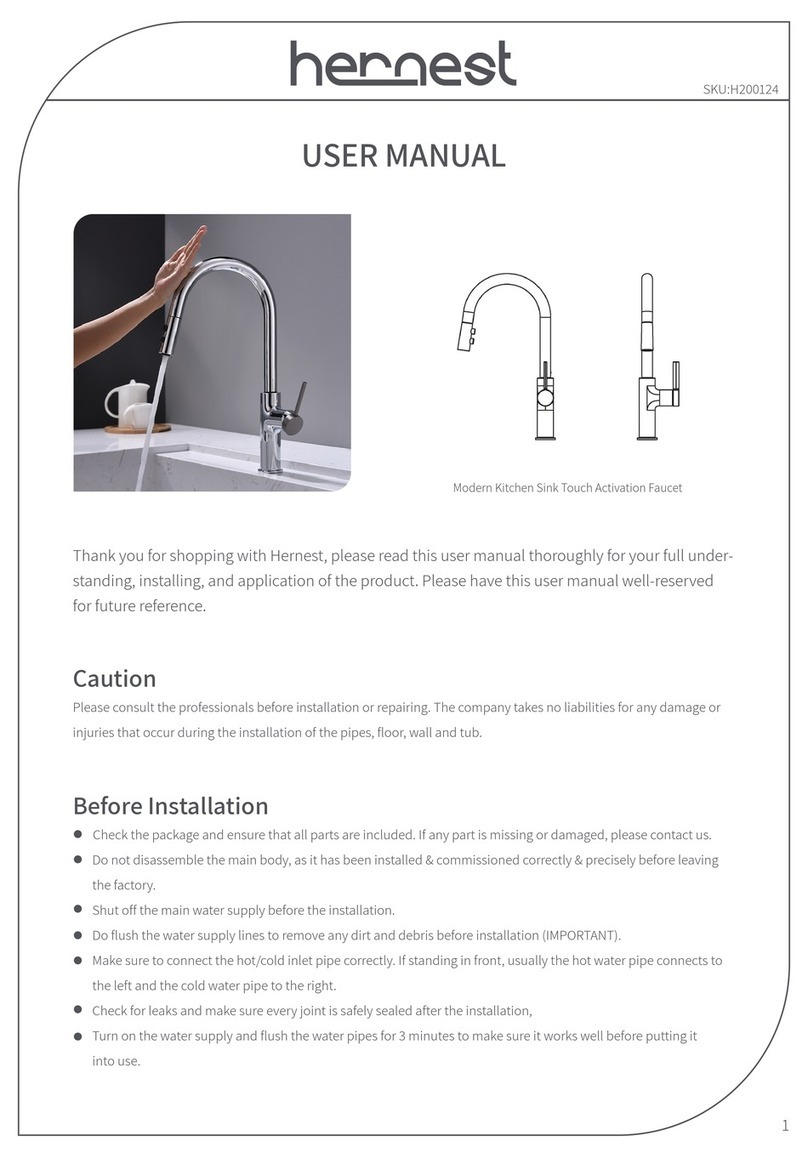
hernest H200228 User manual

USER MANUAL
1
Caution
Please consult the professionals before installation or repairing. The company takes no liabilities for any damage or
injuries that occur during the installation of the pipes, floor, wall and tub.
Thank you for shopping with Hernest, please read this user manual thoroughly for your full under-
standing, installing, and application of the product. Please have this user manual well-reserved
for future reference.
Before Installation
Check the package and ensure that all parts are included. If any part is missing or damaged, please contact us.
Do not disassemble the main body, as it has been installed & commissioned correctly & precisely before leaving
the factory.
Shut off the main water supply before the installation.
Do flush the water supply lines to remove any dirt and debris before installation(IMPORTANT).
Make sure to connect the hot/cold inlet pipe correctly. If standing in front, usually the hot water pipe connects to
the left and the cold water pipe to the right.
Check for leaks and make sure every joint is safely sealed after the installation.
Turn on the water supply and flush the water pipes for 3 minutes to make sure it works well before putting it
into use.
SKU:H200228
Thermostatic Shower Set Large Ceiling Rainfall Shower System

2
Shower Set Installation Guide
16.9"(430mm)
5.1"(130mm)
9.7"(246mm)
2.4”(62mm)
27.6"(700mm)
1.9"(49mm)
0.7"(17mm)
2.4”(62mm)
21.4"(543mm)
ColdHot
Hot Water Cold Water Mixed Water Mixed Water
Unit: Inch(mm)
③
③
④
④
④
②
②
①
①

3
Size Reference
21.3"(543mm)
2.4”(60mm)
5.1"(130mm)
Cover plate installation adjustment gap:
Max 3"(75mm)
2.2"(55mm)
Inlets:3/4"NPT
Outlets:1/2"NPT
Mixer water outlets
Temperature
control handle
Please proceed your installation base your actual size measurement, this image is for reference only.
Installation Steps
1 2 Drill 4 Positioning holes for the valve
body. The image above is for your
reference.
Turn off the water supply, confirm the
length and depth for the pipes. chisel the
groove for waterlines properly based on
the actual situation. Shown as the image
above for reference.( Please note that
hot inlet to the left, cold to the right)
21.3"(530mm)
4.3"(110mm)
Outlet 1
Outlet 2
Outlet 3
Outlet 4
Outlet 5

4
3 4 Fix the valve main body with 4 screws.
Insert the 4 expansion screws into the
holes with a hammer.
5 6 Connect the hot/cold inlets and outlets
properly. Turn on the water supply to
check for leakage and blockage of
connections.
Tighten the screws with a copper sleeve
wrench.
7 8 Install the handles by screwing them on
the switches.
Check the temperature setting. a. Rotate
the valve core by hand to align the 2
marks on the valve core marks(enlarged
view A); b. Attach the black gear ring on
the valve core as the image shown(en-
large view B). c. Install the handle and
plug as picture shows.
Rainfall
Waterfall Bubbles
Body jets
Hand shower
Enlarged view A
Enlarged view B
Leak Block
Align the mark line
Gear(Hot stop) position
Attach this black plastic ring
onto the valve stem with
the hot stop gear opening
facing right.
X X

5
1 2 Wrap the thread of the body jet with
Teflon.
Screw cover plate with the body jet.
Installation Steps Of Hand Shower
Installing The Body Jets
1 2 Install the shower holder on the water
inlet and tighten it clockwise.
Wrap the the thread of connector with
sealing tape.
3Connect the shower head, the shower fixture, and the shower hose, then place the shower on the
shower fixture.
3Screw the body jet on to the spray outlets on the wall tightly clockwise with a wrench. Repeat the process and
install the other body jets.
Hand shower
Sealing Rubber Ring
Shower Hose

6
Installing The Touch Switch
1 2 Use a tool(not included) to crack the
groove on the top to open the front
touch panel. (Take note and do not
break the transmission belt )
Prepare the groove and install the
electrical bottom box on the wall, size
reference: 3.4(86mm) side length.
3 4 Align the top protruding part with the
groove of the touch panel, and cut a
small opening to the bottom.
Fix the main part of the touch switch
onto the electrical bottom box as the
image shows.
5 6 Cover up the wires(in the wall or with
duct cable cover raceway)
Put the power cord through the bottom
opening at the touch panel’s bottom.
Electrical bottom box
(not provided)
Use a tool’s flat and thin part (like a slotted screwdriver)
to insert and crack the top groove
Transmission
belt
The plug connects
to shower head
Protruding align
to the groove
Power cord
wire
Cut a small opening with a tool
(like a screwdriver)
The plug connects to power source
Touch panel
3.4"(86mm)
3.4"(86mm)

7
7 8 Connect the power cord and power
plug.
Cover the front panel of the touch switch
and its main body.
Installing The Touch Switch
NO. Item QTY
8
1
1
1
1
1
4
1
1
4
4
3
1
1
①
②
③
④
⑤
⑥
⑦
⑧
⑨
⑩
Expansion screws
Frame
Connect hose 1
1/2 thick weaving hose
Connect hose 2
Connect hose 3
Screw nuts
Top shower main part
Panel
Connector
Screw
Inlet weaving hose
Power connector
Power plug
11
12
12
13
13
14
14
②
③
④
⑤
⑥
⑦
⑧
⑨
⑩
①
11

8
Installing The Touch Switch
1 2 Separate the shower parts and main
body.
Loosen the 4 screws by unscrewing
them with the hexagon wrench counter-
clockwise.
3 4 Drill 8 holes with φ 12mm in the groove
based on the actual size of the product.
Chisel the groove on the ceiling based
on the actual size of the product.
5 6 Disassemble and take down the nut,
spring washer, and the gasket.
Insert the 8 screws into the holes with
hammer.
19.8"(503mm)
13.1"(333mm)
8*φ0.5"(12mm)
22.2"(565mm)
8.7"(220mm)
12.4"(315mm)
15"(380mm)
22.2"(565mm)
15"(380mm)
Hexagon wrench
Gasket
Spring washer
Nut
Wrench

9
7 8 put the gasket and spring washer back
on the screw, and tighten the nuts on
them with a wrench, make sure the
frame is level with your ceiling.
Install the frame, make the protruding
parts of the 8 screw align and through
the corresponding holes.
9 10 Connect the 4 1/2 inlet weaving hoses
with their corresponding connectors.
Remove the plaster board of the ceiling,
put the 1/2 inlet weaving hose through
the hole on the frame's side, and
connected to the ceiling inlet hole.
11 12 Connect the power connector and the
power plug, and insert the plug the
socket.
Put the light connector through the hole
on the frame’s side, and connect to the
power source plug.
Protruding part of the expansion screws
Frame
Frame
Light connector
Power connector
Rainfall
Atomizing
Bubble
Waterfall
Waterfall
Atomizing
Bubble
Rainfall
Frame
1/2 inlet weaving hose
1/2 thick weaving hose
Frame
Protruding part of the
expansion screws
Gasket
Spring washer
Nut
Wrench

Precautions & Maintenance
Use the product gently and slowly to last the durability.
Clean the filter regularly.
When the water flow gets obstructed after using for long time, please gentle clean the rubber tips on the shower to
get rid of the debris.
Use soft liquid or glass detergent with soft water to rinse the filth on the surface.
Avoid using any scrubbing detergent, polisher, sandpaper/cloth/scraper.
Avoid using acid detergent, insoluble$grain-like detergent or soap.
Turn of the water supply if the shower set won't be used for long.
Keep the equipment warm when the ambient temperature below 0℃/32F to avoid freezing.
10
13 14 Finishing the installation
Fix the shower panel with the hexagon
wrench.
Hexagon wrench
For more detail information, please check out www.hernest.com
It will be our pleasure to have your visit.
After-Sale Service
If you have any issues with the product, please feel free to contact us online or by phone for customer service.
Phone Number: (909) 430-1666
www.hernest.com
Table of contents
Other hernest Plumbing Product manuals
Popular Plumbing Product manuals by other brands

Kindred
Kindred Plumbing Product installation instructions
SUMERAIN
SUMERAIN S1408CW installation guide

BELLOSTA
BELLOSTA revivre 7531/LB manual
jaquar
jaquar JSA-NAW-MD3150IH user manual
Hans Grohe
Hans Grohe PuraVida 15447 Series Instructions for use
Triton
Triton AS2000XT Installation and operating instructions

Hans Grohe
Hans Grohe Talis M52 170 2jet 32841000 Instructions for use/assembly instructions

Signature Hardware
Signature Hardware PRESIDIO 948775 instruction manual
Elkay
Elkay LK722AC Specifications
Fisher
Fisher 2445 Product installation guide

Delta
Delta 467-SS-DST manual
Delta
Delta 53T5 Series instruction sheet
