Hernon Ultracure 6 User manual

Hernon Manufacturing
107-022 Ultracure 6
1 | P a g e
Ultracure 6
LED UV Curing System
107-022
121 Tech Drive
Sanford, FL 32771
www.Hernon.com
Phone: (407) 322-4000 Fax: (407) 321-9700
September 2015

Hernon Manufacturing
107-022 Ultracure 6
2 | P a g e
About This Manual
Thank you for selecting Hernon's Ultracure 6 for your application. The Ultracure 6 was developed with
your needs in mind. Your Ultracure 6 has been calibrated and tested to ensure optimal performance and
long life.
To ensure safe and trouble-free operation, please review the procedures and warnings contained in this
manual before setting up or operating your Ultracure 6. While safety is paramount, proper handling and
operation of Ultracure 6 will also serve to produce quality product yield.
Hernon Manufacturing designs and builds a wide range of custom manufacturing and packaging
machines. Hernon Manufacturing machines are built only with high quality components of proven
reliability.
This Manual is published by Hernon solely as a guide for Operators, Design Engineers, OEM Customers,
and Maintenance Personnel. Liability for difficulties arising from unknown or unforeseen technical
limitations is disclaimed, and Hernon makes no representation as to the thoroughness of this manual.
Hernon reserves the right to revise this manual at any time without notice, for any reason.
If you have any problems or concerns, please contact Hernon Technical Support at (407) 322-4000.
Trained Hernon professionals are standing by to serve you.
IMPORTANT
These instructions are general. Specific cure times should be evaluated and
recommended by Hernon’s Lab. Please contact Hernon’s Technical Department
(407)322-4000 for specific instructions.

Hernon Manufacturing
107-022 Ultracure 6
3 | P a g e
Table of Contents
Ultracure 6 .................................................................................................................................................... 1
About This Manual........................................................................................................................................ 2
Table of Contents.......................................................................................................................................... 3
Unpacking and Inspection............................................................................................................................. 4
Safety ............................................................................................................................................................ 5
General.......................................................................................................................................................... 6
Features .................................................................................................................................................... 6
Specifications ............................................................................................................................................ 6
Mounting............................................................................................................................................... 7
Operation Guidelines.................................................................................................................................... 8
Wiring Configurations ............................................................................................................................... 8
System Status/Faults............................................................................................................................... 11
UV Output Curve.....................................................................................................................................11
External I/O Signals .................................................................................................................................12
LED Failure .............................................................................................................................................. 12
Maintenance ...............................................................................................................................................13
Frequently Asked Questions .......................................................................................................................13
Replacement Parts...................................................................................................................................... 13
Warranty .....................................................................................................................................................14
Notes...........................................................................................................................................................15
Hernon Manufacturing
107-022 Ultracure 6
4 | P a g e
Unpacking and Inspection
Upon receipt of the unit, carefully remove the contents from the boxes and check for damage. Hernon is
not responsible for damage from shipping –all claims for shipping damage should be made with
carrier.
Check all boxes for contents and document any serial numbers for further reference. You may wish to
retain original shipping cartons in case you need to repackage any item for return.
If you observe or experience any problem with your equipment, notify Hernon Customer Support, your
authorized distributor, or your Hernon representative immediately.
NOTE: REPORT ANY SHORTAGE TO HERNON CUSTOMER SERVICE
Phone: (407) 322-4000
Fax: (407) 321-9700
Email: sales@hernon.com
Before continuing with unpacking and installation, please read the following chapters of this manual for
safety recommendations and installation, running, and troubleshooting instructions.
CAUTION! Always wear proper (High Intensity UV Blocking) protective goggles or face shield
when working near the front of the unit which emits Ultraviolet light! Note: Reflected UV
light may be harmful.
WARNING! Always observe safety requirements!
CAUTION! Risk of Electrical Shock when cover is removed!
CAUTION! Cover is warm to the touch when unit is in operation!
WARNING: DANGEROUS ULTRAVIOLET EMMISSION

Hernon Manufacturing
107-022 Ultracure 6
5 | P a g e
Safety
Please, read all safety specifications before performing any procedures such as checking products on
delivery, storage and transportation, installation, wiring, operation and inspection, or disposal. Be sure
to observe these precautions thoroughly.
GENERAL WARNINGS
All operators and maintenance personnel are required to read this safety
instruction list before attempting to operate, adjust, or repair.
Never operate with electrical enclosure open.
Do not operate this or any other machine without all protective guards and
covers in place.
Do not operate this device before reading and understanding the operator’s
procedures in this manual.
Any electrical servicing or adjustments requiring access to electrical enclosures on
the machine should be performed only by qualified personnel with electrical
power disconnected and locked out.
Safety glasses must be worn by the operator and any one in the area of
operation. W/ #5 Green Shade Goggles.
Hands should never be placed near moving or illuminated areas.
Disconnect and lock out electrical power, hydraulic power, air pressure and water
before performing machine or tooling adjustment and or maintenance.
Keep area around device/s clear of all debris, water, oil, etc.
Use only genuine OEM Hernon replacement parts when servicing this machine
tool. Ignoring this warning could cause unintended operation and possible injury.
WARNING: DANGEROUS ULTRAVIOLET EMMISSION (Hernon Part Number: 107-005)
Recommended #5 Green shade goggles for eye protection
This equipment is designed to be used properly set up with components correctly connected, and
operated in accordance with relevant instructions. Its design was developed to maximize operator
safety.

Hernon Manufacturing
107-022 Ultracure 6
6 | P a g e
General
Features
Ultra Violet Energy (UVA) Curing
Self-cooled
365nm High Output LED
Built-in power regulation and overheating protection
Compact design
Specifications
Part Number
107-022
Power Requirements
24VDC, 700 mA
UV Output
2.5 /W cm² (max) @ 365nm
I/O Port
5 pin CPC
Cooling
Fan
Dimensions (approx.)
6” x 2” x 1.5”
System Warranty
1 year from purchase
NOTE: Power Supply not included.
Figure 1- Ultracure 6 dimensions and mounting specifications.
Hernon Manufacturing
107-022 Ultracure 6
7 | P a g e
Mounting
The Ultracure 6 has two mounting options. Four M3 x 0.5 on electrical connector end, and four M2 x 0.4
on the bottom of the device. Refer to Figure 1. When mounting the Ultracure 6, do not to mount directly
onto any surface that may obstruct the fan. Hernon recommends using at least a quarter inch (0.25”,
6.35mm) clearance between the mounting surface and the surface of the device; this is to ensure that
the Ultracure 6 has optimal airflow for regular operation.
NOTE: M3 x 0.5 mounting holes are supplied with fasteners which act as plugs covering and protecting
enclosure from dust, dirt or any other debris. 3mm Fastener should never thread in excess of 6mm
distance into housing. Extra-long screws may permanently damage electronics.
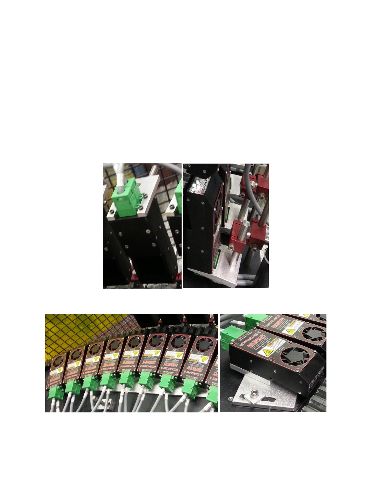
Mounting Examples
Below are examples of how to mount the Ultracure 6.
Figure 2- Ultracure 6 back face mounting, M3 x .03
Figure 3- Ultracure 6 bottom face mounting, M2 x .04

Hernon Manufacturing
107-022 Ultracure 6
8 | P a g e
Operation Guidelines
Wiring Configurations
The Ultracure 6 can be wired with or without status feedback.
Quick Install –No Feedback
Connect 24VDC as shown for quick install with no feedback.
Figure 4 - Ultracure 6 pin connectors, with pins labelled.
Single Unit Wiring with Feedback Status I/O
Reference Drawing on next page.
The Ultracure 6 unit will turn on under the following conditions: when the Power Supply (PS1) is on, the
Switch (SW1) is closed, and shutter relay contacts are open.
If the unit has an over temperature error or a burned out LED, the error relay will turn on, opening up
the NC contacts.
Pin #1
(Error NC)
Pin #2
(Error COM)
Pin #3
(Shutter)
Pin #4
(-)
Pin #5
(+)
Upper Connector
Lower Connector

Hernon Manufacturing
107-022 Ultracure 6
9 | P a g e
The Ultracure 6 unit will turn on/off quickly when the shutter relay contacts are opened/closed. If the
shutter relay is not used, leave Pin 3 disconnected and the unit will turn on and off with SW1 only. The
cooling fans will be turned off with SW1 as well. DO NOT connect Pin 3 to anything over than 24
RETURN! Status Relay Contacts in each unit are rated for 30VDC and 2A.
Multi-Unit Wiring with Feedback Status I/O
Reference Drawing on next page.
When PS1 is on, switch SW1 is closed and shutter relay contacts are open then all the Ultracure 6 units
in the Multiunit loop will turn on. The green LED on each unit will turn on when the units are on. If one
of the units has an over temperature error or a burned out LED then that units’ error relay will turn on
and the error loop will open. The red LED will turn on when an error is active. The Ultracure 6 units will
turn on/off quickly when the shutter relay contacts are opened/closed. If the shutter relay is not
used/required then leave Pin 3 disconnected and the units will turn on/off with SW1 only. The cooling
fans will be turned off with the SW1 as well. DO NOT connect Pin 3 to anything other than 24 RTN of
this multi-unit loop! Status Relay contacts in each unit are rated for 30VDC and 2A.

Hernon Manufacturing
107-022 Ultracure 6
10 | P a g e
Hernon Manufacturing
107-022 Ultracure 6
11 | P a g e
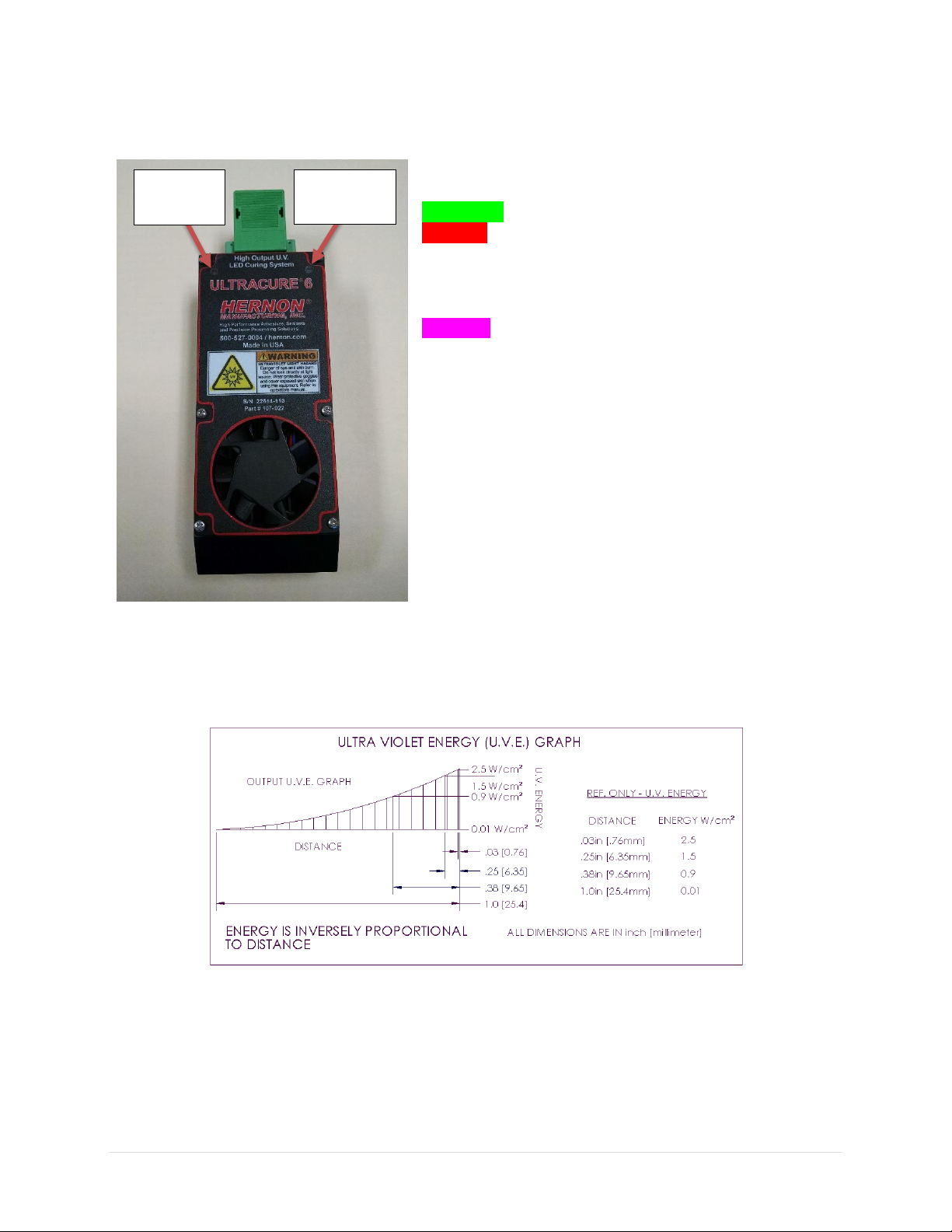
System Status/Faults
Two status indicator LED’s are located on top of the
module.
Green lamp: Power on and working properly.
Red lamp: Indicates one of the following Fault Conditions:
LED failure open
LED short
Pink lamp: Over temperature
If the fan fails, or the ambient temperature gets too
high, an automatic shutdown will protect the LEDs. The
LEDs are forced off if the unit temperature reaches 60°C,
and will stay off until the substrate cools down to 55°c.
UV Output Curve
The Ultracure 6 has an optimal distance for ideal curing properties. The diagram below shows the UV
Intensity vs Distance Curve.
Figure 5- UV output curve.
Power LED
(PWR)
Fault LED
(FLT)
Hernon Manufacturing
107-022 Ultracure 6
12 | P a g e
External I/O Signals
The only output signal on the Ultracure 6 is an Error signal from port 2. Refer to Figure 4.
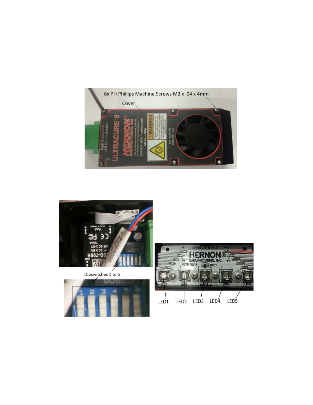
LED Failure
In the event that the unit has experienced LED failure:
1. Open the enclosure, via six Philips-head M2 screws.
2. Flip the corresponding dipswitches one at a time, from 1 to 5, until the unit turns back on. The
unit will operate properly with one or more inoperable LEDs.

Hernon Manufacturing
107-022 Ultracure 6
13 | P a g e
Maintenance
Inspect that the fan is clean before powering up for regular operation. This will ensure a long life of the
Ultracure 6.
Verify the protective glass is clean.
Frequently Asked Questions
Q: Why is my unit turning off by itself?
A: The unit has overheated from lack of airflow. Clean the fan. If the problem persists, replace the fan.
AA: LED failure, refer to next question for answer.
Q: The unit no longer turns on, but the unit is not hot. What happened?
A: The unit has experienced an LED failure; this is fixed by opening the driver enclosure and flipping the
corresponding dipswitches one at a time (from 1 to 5) until the unit turns back on. The unit will operate
properly with one or more inoperable LEDs.
Q: How often should the Ultracure 6 be cleaned?
A: The unit should be cleaned prior to every start up. This will ensure a long life of the fan, and the LEDs.
Q: How should I clean the fan?
A: The fan should be cleaned with bursts of low pressure compressed air, and a light duty brush.
Replacement Parts
Below is a list of recommended replacement parts that should be kept on hand in order to minimize
machine downtime due to normal wear or unexpected failure.
Part Number
Description
Quantity
Price
102-086
Fan
1
Call For Price
106-135
Protective Glass
1
Call For Price
102-130
Connector Cover
2
Call For Price

Hernon Manufacturing
107-022 Ultracure 6
14 | P a g e
Warranty
CAUTION!
HERNON CORPORATION RESERVES THE RIGHT TO INVALIDATE ANY WARRANTIES, EXPRESSED OR
IMPLIED, DUE TO ANY REPAIRS PERFORMED OR ATTEMPTED ON HERNON EQUIPMENT WITHOUT
WRITTEN AUTHORIZATION FROM HERNON. THOSE CORRECTIVE ACTIONS LISTED BELOW ARE LIMITED TO
THIS AUTHORIZATION.
Hernon offers a one-year warranty against defects in material and workmanship on all system
components, except the LED/Fan, with proof of purchase date. Unauthorized repair, modification, or
improper use of equipment may void warranty. The use of aftermarket replacement parts not supplied or
approved by Hernon will void any effective warranties and may result in damage to the equipment.
The data contained in this bulletin is furnished for information only and is believed to be reliable. We cannot assume
responsibility for results obtained by others over whose methods we have no control. It is the user’s responsibility
to determine suitability for the user’s purpose of any product or methods mentioned herein and to adopt such
precautions as may be advisable for the protection of property and persons against any hazards that may be involved
in the handling and use thereof. Nothing in this bulletin is to be interpreted as a representation of freedom from
domination of patents owned by others or a license under a Hernon patent. We recommend that each prospective
user test his proposed application before repetitive use, using the data as a guide.

Hernon Manufacturing
107-022 Ultracure 6
15 | P a g e
Notes
This manual suits for next models
1
Table of contents
Other Hernon Industrial Equipment manuals


