HERO 8 User manual

SPECIFICATION:
The HERO 8 Way Contactor + Heater can control the timing of:
Lighting sockets: 8 x 600W HPS Lighting systems or 4 x 1000W HPS lighting systems.
Not recommended for use with LED lighting due to the in-rush of current on start-up.
Heater sockets: total load of 2500W.
INSTRUCTIONS
8 WAY CONTACTOR + HEATER
Please read the instructions before operating the unit.

SAFETY FIRST:
Prior to set-up or maintenance, ensure that the unit is disconnected from the power
supply.
Ensure that the unit remains in a dry area and that it is not accessible to people unfamiliar
with its operation.
The unit is intended for switching the electrical load associated with HID (High Intensity
Discharge) lighting with a total load not exceeding either 8 x 600W or 4 x 1000W.
The unit has two power cords, each capable of carrying up to 13 A. The power cord on
the left hand side is the ‘master’ power cord and also supplies power to the timer and
contactor. The left hand side should be plugged in for the unit to function.
Check the input current required by your individual HPS lighting systems, the total current
required by all lighting systems on either side of the unit should not exceed 13A. For
safety reasons, any load applied to the unit should be evenly distributed across both sides.
Do not plug the unit into extensions or adaptors as the current will be too high for these
and may create a risk of fire.
Upon switching the unit off, leave at least 5 minutes before unplugging it to allow any
connected appliances to safely discharge.
INSTALLATION
To mount the unit on a wall use the installed brackets as shown below.
Four brackets are pre-installed on the unit. Fit a fixing through the hole in the bracket
and fix to the mounting surface.
2

INITIAL SET UP
Please note:
The timer must be set up before
connecting any lighting or heaters,
and the unit must be connected
to power.
Gain acces to the timer by opening
the covers.
Ensure that the timer switch
is in the ‘0’ position.
UNDERSTANDING THE TIMER
The timer is dual purpose, it acts as the clock for the unit and a segmental timer to turn
the sockets ON and OFF at the desired times.
3
6
9
15
18
21
3
6
9
15
18
21
The inner part, is the clock for the unit.
This must be set so the timer turns on
and off at the correct times.
The outer part of the timer has
segments that are used to
program the ‘ON’ times.
‘0’ position = Lighting sockets OFF / Heater sockets ON.
‘1’ postiton = Lighting sockets ON / Heater sockets OFF.
position = the Lighting & Heater sockets will switch ON / OFF based on the timer.
3

The timer is 24 hour. When the numbers on the inner clock dial show 3,6& 9 this indicates
AM. When the numbers on the inner clock dial show 15,18 & 21 this indicates PM.
For example:
Turn the grey
centre pin
clockwise to
set the time. Hour hand
SETTING THE TIMER (CURRENT TIME)
To set the current time on the clock (inner part), turn the minute hand clockwise, via the
centre pin. Totally disregard the segmental timer around the clock.
SETTING THE TIMER (PROGRAM TIMES)
Set your required ON/OFF periods by pushing the segments in towards the centre of
the clock for the ON periods.
3
6
9
Current
time shows
3.00am
Current
time shows
3.00pm
13
15
18
21
These segments turn the
sockets ON or OFF
In this example the lights
would be ON from
8.00AM to 8.00PM
4

CONNECTING LIGHTS AND HEATER
Plug the HPS lighting systems into the sockets of the unit. Ensure that the electrical load is
balanced and does not exceed the specification. If you are connecting 4 lights, plug 2
lights into one side and 2 in the opposite side to spread the load.
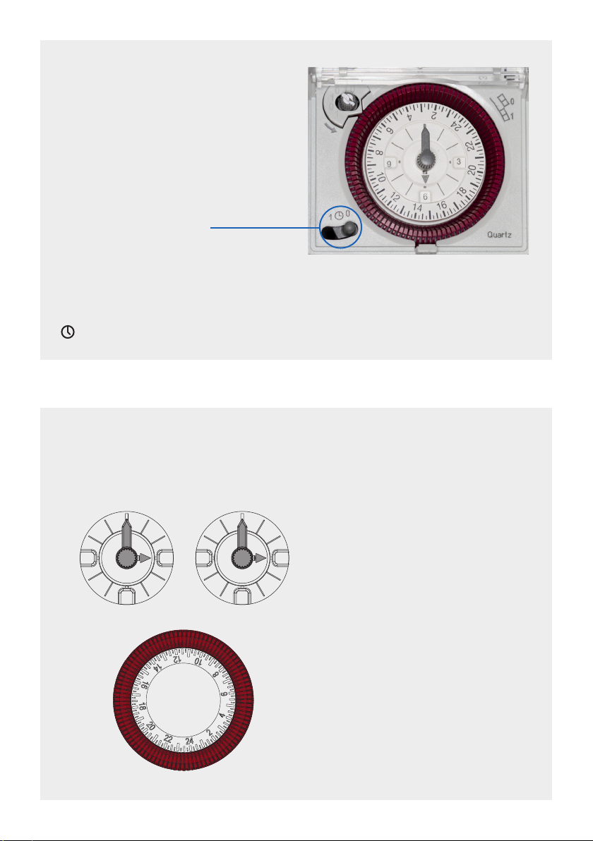
TURNING THE UNIT ON
To activate the timer, ensure that the switch is in the middle position.
You can verify that the unit is working by moving the timer switch
to ‘1’ to check the lights power up, and position ‘0’ to check the
heaters power up. Once the check is complete move the switch
back to the middle (timer) position.
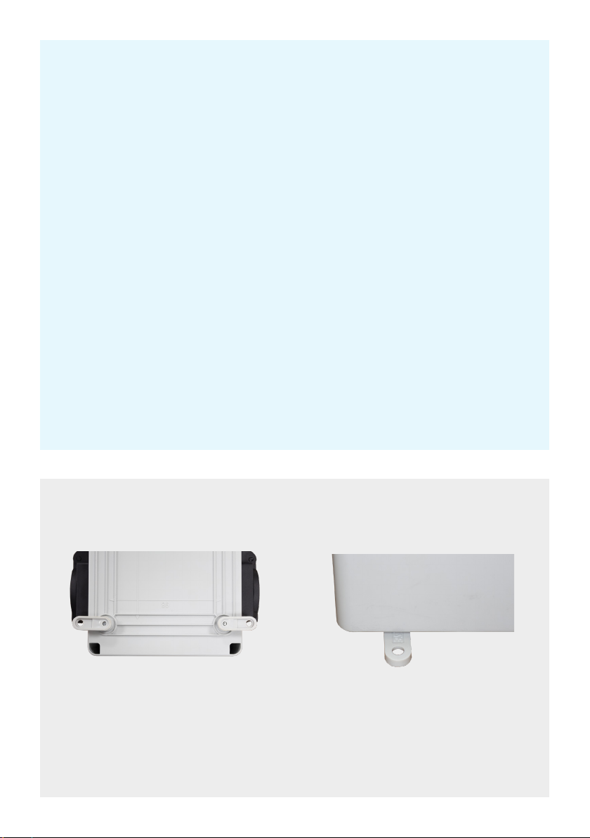
RESETTING THE CIRCUIT BREAKER
There are 2 circuit breakers, the left circuit breaker is connected to the sockets on the left
hand side and the heater sockets. The right circuit breaker is connected to the sockets on
the right hand side.
If the unit is overloaded, the breaker will trip, and cut the power to one bank of 4 sockets.
Before resetting the circuit breaker, disconnect all lights and/or heater from the bank that
has lost power.
Set the switch to position ‘1’ and re-attach each light individually.
If the breaker trips when reconnecting a light, this indicates that the circuit is overloaded,
or there is a problem with one of the lights.
If the left hand breaker has tripped, turn the timer switch to ‘0’ and reconnect your
heater(s) to the heater sockets. If the breaker trips, the heater is overloading the circuit, or
has an electrical problem.
Once you have resolved the issues, turn the switch back to the middle position (timer).
Reset the breaker by pushing the
switch to the up position.
This example shows the left circuit
breaker has turned off the power supply.
5

TROUBLESHOOTING
If you suspect that the unit is faulty, it can be verified by plugging a known working appliance
into each socket in turn. If any individual socket fails, return the unit to the retailer you
purchased it from.
In the event that your unit has no power to any sockets, or to one side, check the circuit
breakers have not tripped and change the main fuse in the plugs if required.
To replace the fuse, remove the plug from the socket and prise the fuse carrier out of the plug
with a small screw driver. Replace with a 13amp fuse and push back into the plug.
If the circuit breakers keep tripping, this is an indication that the load being used is too large.
WARRANTY AND LIABILITY
In the unlikely event that there should be a fault with the unit, please return it to your retailer.
The unit carries a 2 year warranty (terms and conditions apply).
There are no user serviceable parts inside and tampering with the unit will
void the warranty.
The manufacturer will not be liable for any damage caused by operation of the unit.
Manufactured in the EU for:
Global Air Supplies
Unit 36 Meadows Rd
Wath upon Dearne
Rotherham
S63 5DJ
Table of contents
Popular Heater manuals by other brands

BIEMMEDUE
BIEMMEDUE 163100 instruction manual

Cadet
Cadet Apex72 owner's guide

Drazice
Drazice MX2207 OPERATING AND INSTALLATION Manual

Dyna-Glo
Dyna-Glo EG5000DGC Installation & maintenance instructions

Truma
Truma Trumatic E 2800 A operating instructions

Heatstore
Heatstore HSACR3000N Installation, operation and maintenance instructions