Herth+Buss ELPARTS 76102068 User manual

ELPARTS
Spannungswandler
Voltage transformers
3
www.herthundbuss.com 2
Bedienhinweis Bedienhinweis
Bedienhinweis
Inhalt
1. Anschlussvariante
Eingangs-
spannung
V
Ausgangs-
spannung
V
Nennleistung
W
Stromstärke A B x H x T
mm
Gewicht
kg
Artikel-
Nr.
48 12 72 6 87 x 50 x 89 0,32 76102068
24 12 72 6 87 x 50 x 89 0,27 76300006
50 x 87 x 127 0,405 76310006
36 3 87 x 50 x 67 0,225 76300003
67 x 50 x 87 0,29 76310003
144 12 87 x 50 x 127 0,405 76300012
50 x 87 x 167 0,59 76310012
288 24 87 x 50 x 167 0,62 76300024
50 x 87 x 217 0,835 76310024
12 13,6 36 3 87 x 50 x 89 0,29 76200001
12 24 72 3 87 x 50 x 89 0,29 76350008
168 7 50 x 87 x 167 0,62 76350009
240 10 50 x 87 x 217 0,835 76350011
1 x DC-DC Spannungswandler
1 x Montageclip
3 x Schrauben
3 x Schraubabdeckungen
4 x Flachsteckverbindungen
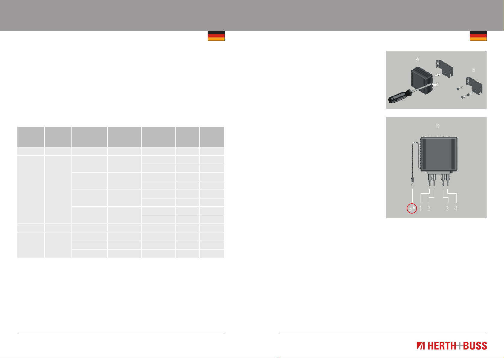
1. Entfernen Sie den Montageclip vorsich-
tig mit einem Schraubenzieher von dem
Gerät (A).
2. Wählen Sie einen kühlen und gut
belüfteten Ort zur Installation, welcher
nicht in direkter Sonneneinstrahlung
liegt und wo das Gerät horizontal oder
vertikal montiert werden kann.
3. Unterbrechen Sie die Stromversorgung
zur Verkabelung bevor Sie mit der
Installation beginnen.
4. Benutzen Sie den Montageclip als
Schablone und markieren Sie die
Befestigungspositionen.
5. Bohren Sie die drei Ø 3,5mm Löcher
für die Schrauben. Stellen Sie sicher
das keine, bereits vorhandenen,
Kabel beschädigt werden können.
6. Befestigen Sie den Montageclip mit
den enthaltenen Schrauben.
7. Bringen Sie die Schraubenabdeckungen
an (B).
8. Führen Sie das Gerät in den Montageclip
und drücken Sie es fest bis es einrastet.
Bitte beachten Sie, dass das Führungs-
stück in die Aussparung am Montageclip
passt (C).
9. Schließen Sie den Verbraucher und
das Erdungskabel richtig an*.
10. Schließen Sie die Stromversorgung
wieder an.
B
A
D
1 2 3 4
5*
Anschlüsse
Unterbrechen Sie die Stromversorgung
bevor Sie das Gerät anschließen oder
entfernen. Schließen Sie das Gerät wie in
Zeichnung (D) an.
1 Eingang Positiv
2 Eingang Negativ
3 Ausgang Negativ
4 Ausgang Positiv
5* Erdungskabel: Das Erdungskabel
ist nur bei galvanisch getrennten
Geräten vorhanden.

5
www.herthundbuss.com 4
Bedienhinweis
Bedienhinweis
Eingangs-
spannung
V
Ausgangs-
spannung
V
Nennleistung
W
Stromstärke A B x H x T
mm
Gewicht
kg
Artikel-
Nr.
12 24 400 16 74 x 233 x 125 1,61 76350012
600 25 74 x 283 x 125 1,86 76350013
Anschlüsse
Unterbrechen Sie die Stromversorgung
bevor Sie das Gerät ein oder ausbauen.
Schließen Sie das Gerät wie in der Skizze
(D) mit einem 10mm2 Kabel an.
1. Eingang Positive (13,6V)
2. EingangNegative (0V)
3. Ausgangsfreigabe (Active High)
4. Ausgang Negative (0V)
5. AusgangPositive (27,2V)
Eingangs-
spannung
V
Ausgangs-
spannung
V
Nennleistung
W
Stromstärke A B x H x T
mm
Gewicht
kg
Artikel-
Nr.
24 12 36 3 87 x 50 x 67 0,25 76100065
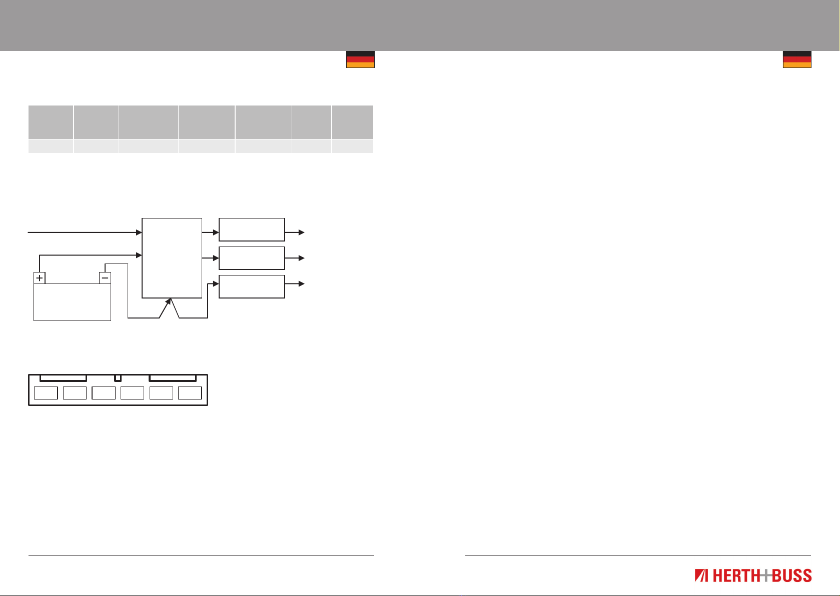
Die Lösung
Zündung 12V
geschaltet
12V Dauer-
strom
0V
Strom
24V
Batterie
24V – 12V
Spannungs-
wandler
Artikel-Nr.
7610065
Eingang Ausgang0V
Geschaltet konstant Geschaltet konstant
LED
Anschlusslösung:
2. Anschlussvariante 3. Anschlussvariante
7
www.herthundbuss.com 6
Bedienhinweis
Bedienhinweis
Eingangs-
spannung
V
Ausgangs-
spannung
V
Nennleistung
W
Stromstärke A B x H x T
mm
Gewicht
kg
Artikel-
Nr.
24 12 144 12 87 x 42 x 126 0,455 76100064
Die Lösung
Zündung 12V
geschaltet
12V Dauer-
strom
0V
Strom
24V
Batterie
24V – 12V
Spannungs-
wandler
Artikel-Nr.
7610064
Anschlusslösung:
6 5 4 3 2 1
4. Anschlussvariante Sicherheit:
1. Das Gerät darf nicht extremen mecha-
nischen Schocks, hohen Temperaturen,
direkter Sonneneinstrahlung oder starken
Vibrationen ausgesetzt werden.
Außerdem soll es nur in einer trockenen
Umgebung installiert werden wie zum
Beispiel ein Fahrzeug.
2. Während des Betriebs kann das Gerät
heiß werden daher sollte das Gerät so
installiert werden das es nicht einfach
zugänglich ist.
3. Das Gerät nicht auf heißen Fahrzeugteilen
installieren und genügend Platz für Luft-
zirkulation und Kühlung gewährleisten.
4. Den Kabelbaum durch Sicherungen
schützen.
5. Die Stärke und Polarität des Ausgangs
sollte bei der Installation beobachtet
werden. Inkorrekte Polarität am Ausgang
könnte den Schaltkreis beschädigen.
6. Den Schaltkreis isolieren bevor das
Gerät ein- oder abmontiert wird.
7. Der Ausgang des Gerätes darf nicht
kurzgeschlossen sein.
8. Sollte das Gerät defekt sein muss es
ausgetauscht werden. Das öffnen des
Gehäuses oder die Reparatur des
defekten Gerätes ist untersagt.
9
www.herthundbuss.com 8
Operating Instruction
Operating Instruction
Content
1st connection variant
Input
voltage
V
Output
voltage
V
Rated capacity
W
Rated current
[A]
W x H x D
mm
Weight
kg
Article
no.
48 12 72 6 87 x 50 x 89 0.32 76102068
24 12 72 6 87 x 50 x 89 0.27 76300006
50 x 87 x 127 0.405 76310006
36 3 87 x 50 x 67 0.225 76300003
67 x 50 x 87 0.29 76310003
144 12 87 x 50 x 127 0.405 76300012
50 x 87 x 167 0.59 76310012
288 24 87 x 50 x 167 0.62 76300024
50 x 87 x 217 0.835 76310024
12 13.6 36 3 87 x 50 x 89 0.29 76200001
12 24 72 3 87 x 50 x 89 0.29 76350008
168 7 50 x 87 x 167 0.62 76350009
240 10 50 x 87 x 217 0.835 76350011
1 x DC-DC voltage transformer
1 x mounting clip
3 x screws
3 x screw covers
4 x flat blade connections
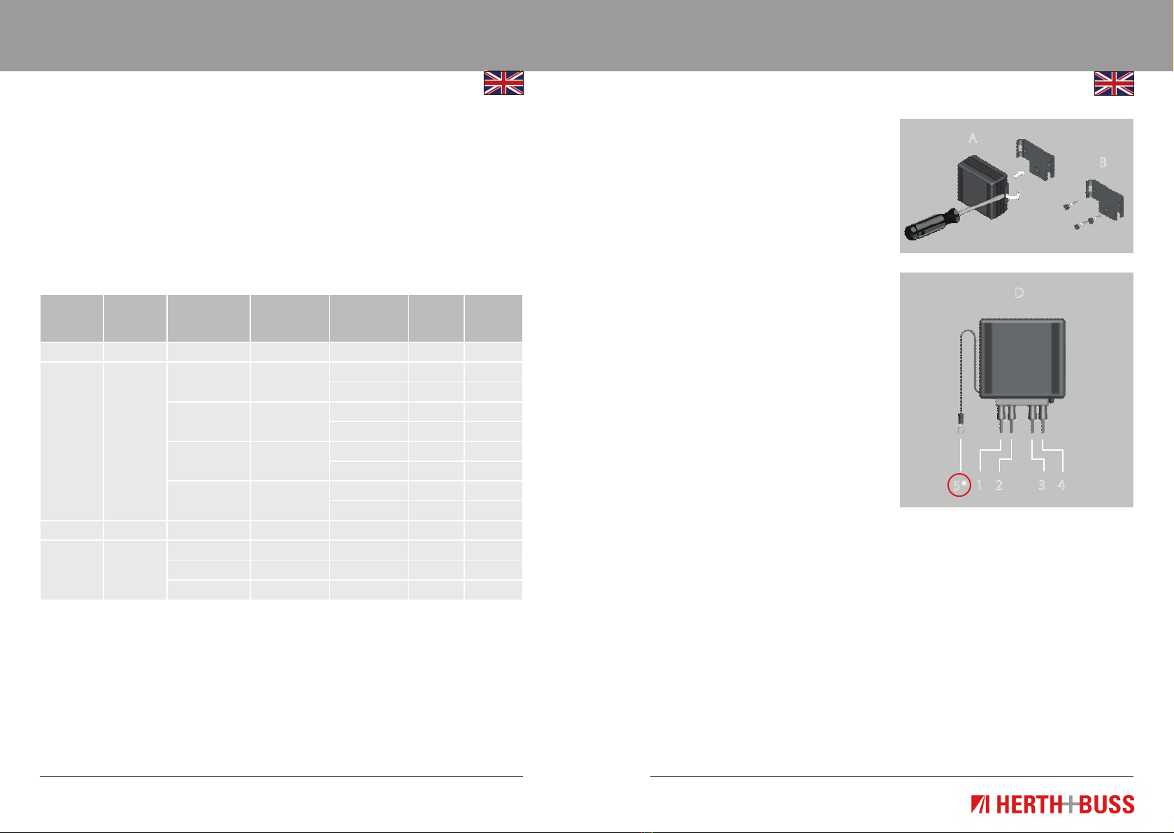
1. Carefully remove the mounting clip
from the device (A) using a screwdriver.
2. For the installation, select a cool and
well-vented location that is not in direct
sunlight and where the device can be
horizontally or vertically mounted.
3. Disconnect the power supply to the
cabling before commencing the
installation.
4. Use the mounting clip as a template and
mark the positions for the fastenings.
5. Drill three Ø 3.5 mm holes for the
screws. Ensure that no existing cables
can be damaged.
6. Secure the mounting clip with the
screws in it.
7. Attach the screw covers (B).
8. Place the device in the mounting clip
and press it in firmly until it locks in
place. Please ensure that the guide
piece fits into the groove on the mount-
ing clip (C).
9. Connect the sink and the earth cable,
ensuring this is done correctly*.
10. Now reconnect the power supply.
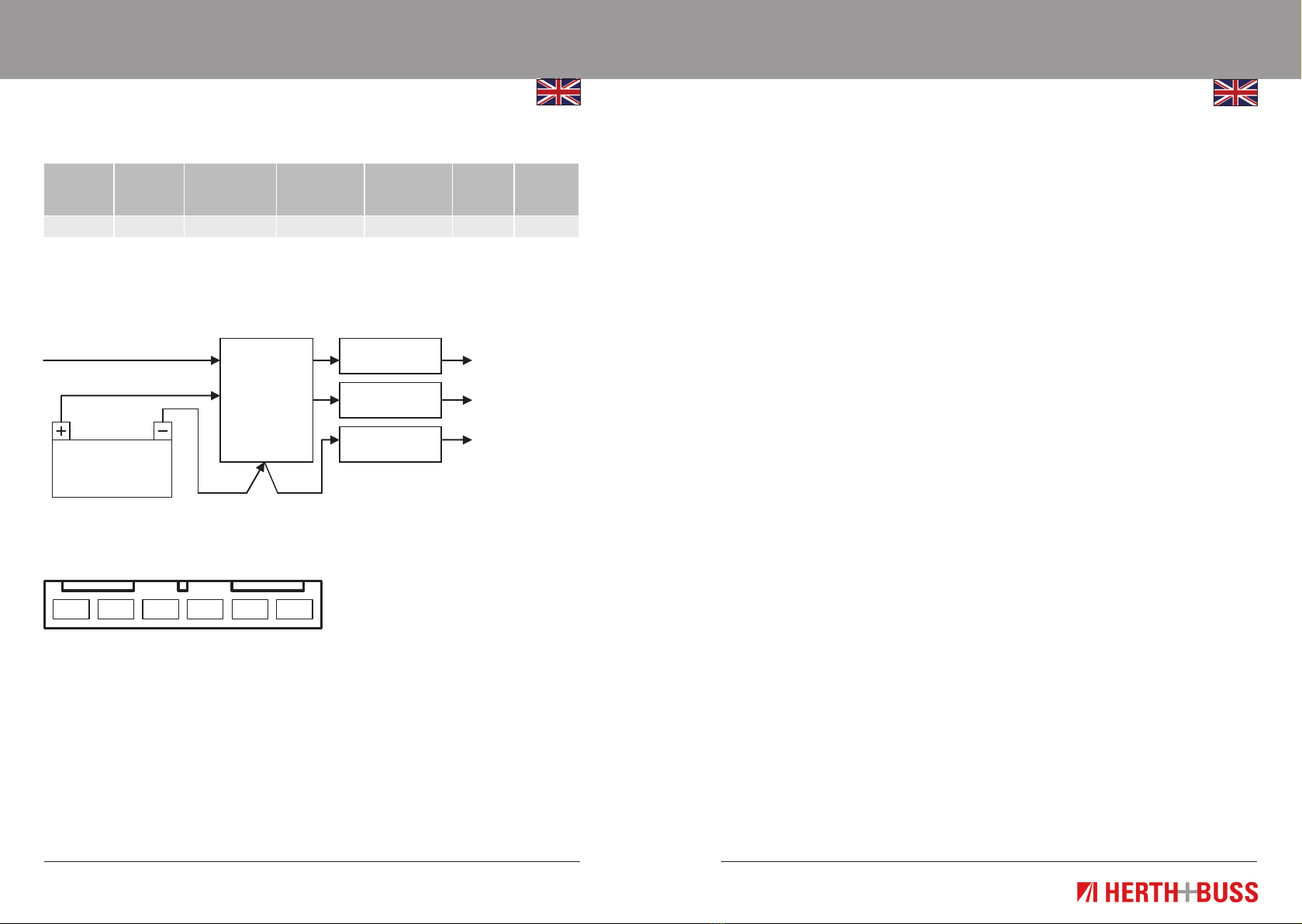
Connections
Disconnect the power supply before con-
necting or removing the device. Connect
the device as shown in Figure (D).
1 Positive input
2 Negative input
3 Negative output
4 Positive output
5* Earth cable:The earth cable is only
present on galvanically insulated
devices.
B
A
D
1 2 3 4
5*
11
www.herthundbuss.com 10
Operating Instruction
Operating Instruction
Input
voltage
V
Output
voltage
V
Rated capacity
W
Rated current
[A]
W x H x D
mm
Weight
kg
Article
no.
12 24 400 16 74 x 233 x 125 1,61 76350012
600 25 74 x 283 x 125 1,86 76350013
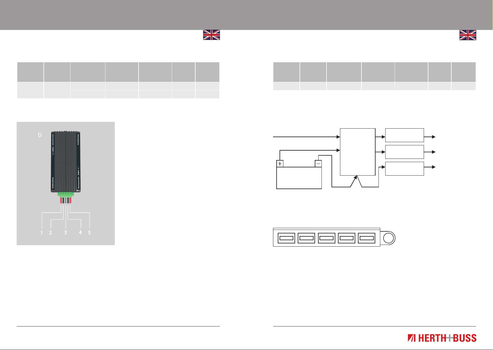
Connections
Disconnect the power supply before
switching the device on or off.
Connect the device as shown in Figure (D),
using a 10 mm2cable.
1. Positive input (13.6 V)
2. Negative input (0 V)
3. Output release (Active High)
4. Negative output (0 V)
5. Positive output (27.2 V)
Input
voltage
V
Output
voltage
V
Rated capacity
W
Rated current
[A]
W x H x D
mm
Weight
kg
Article
no.
24 12 36 3 87 x 50 x 67 0.25 76100065
The solution
Ignition 12V
connected
12V continuous
current
0V
current
24V
battery
24V – 12V
voltage
transformer
Article no.
7610065
Input Output0V
Constantly connected Constantly connected
LED
Connection solution:
2nd connection variant 3nd connection variant
13
www.herthundbuss.com 12
Operating Instruction
Operating Instruction
Input
voltage
V
Output
voltage
V
Rated capacity
W
Rated current
[A]
W x H x D
mm
Weight
kg
Article
no.
24 12 144 12 87 x 42 x 126 0.455 76100064
The solution
Ignition 12V
connected
12V continuous
current
0V
current
24V
battery
24V – 12V
voltage
transformer
Article no.
7610064
Connection solution:
6 5 4 3 2 1
4nd connection variant Safety:
1. The device must not be subjected
to extreme mechanical shocks, high
temperatures, direct sunlight or intense
vibrations.
It must also only be installed in a dry
environment such as inside a vehicle.
2. The device can become hot during
operation, so it should therefore be
installed in such a way that it is not easily
accessible.
3. Do not install the device on hot vehicle
parts and ensure there is enough space
for air circulation and cooling.
4. Protect the cable harness using fuses.
5. The strength and polarity of the output
should be observed during installation.
Incorrect polarity at the output could
damage the circuit.
6. Isolate the circuit before mounting or
removing the device.
7. The device output must not be
short-circuited.
8. If the device is faulty, it must be
replaced. It is not permitted to open
the housing or repair the device in the
case of faults.

15
www.herthundbuss.com 14
Notice
Notizen

Herth+Buss
Fahrzeugteile GmbH & Co. KG
Dieselstraße 2-4
D-63150 Heusenstamm
www.herthundbuss.com
KOF01351 ı Stand: 08-2012
This manual suits for next models
26
Table of contents
Languages:
Popular Transformer manuals by other brands


Pulsar
Pulsar TRZ 40 Series Assembly instructions

Beckhoff
Beckhoff SCT6 Series manual

Harbor Breeze
Harbor Breeze 8201080416-1 quick start guide

Delta Electronics
Delta Electronics Planar Transformer & Inductor E/E 18 Specification sheet

Forch
Forch 6600 6285 manual

Altec Lansing
Altec Lansing T5100 TRANSFORMER manual


