Herutu TW-800R-EXC User manual

Wireless Communication
TW-800R-EXC
Instruction Manual V1.20
Please use this Instruction manual correctly on reading well.
Please keep it carefully to be able to read immediately, when required.


Table of contents
■ Outline...................................................................................................................................................................1
■ A main part and accessories...............................................................................................................................2
■ Safety concerns....................................................................................................................................................3
■ Name and function of each part .........................................................................................................................8
■ Input/output terminal Block ................................................................................................................................9
■ Installation...........................................................................................................................................................10
■ Setting .................................................................................................................................................................13
■ Function ..............................................................................................................................................................15
1. Judgment........................................................................................................................................................15
2. Work................................................................................................................................................................16
3. Count Alarm....................................................................................................................................................17
4. Sensor Input...................................................................................................................................................17
5. Timer ...............................................................................................................................................................17
5-1. Work timer ...............................................................................................................................................17
5-2. Tool timer.................................................................................................................................................17
5-3. Alarm Timer .............................................................................................................................................17
5-4. Reset Timer..............................................................................................................................................17
5-5. Output Time.............................................................................................................................................17
6. Judgment Mode .............................................................................................................................................18
7. Judgment Type...............................................................................................................................................19
8. Sequence........................................................................................................................................................19
9. Over count......................................................................................................................................................19
10. Buzzer Out....................................................................................................................................................19
11. Pass Buzzer..................................................................................................................................................19
12. Buzzer Pattern..............................................................................................................................................19
13. Keylock function..........................................................................................................................................19
■ Screen composition and setting ......................................................................................................................21
1. Screen Composition......................................................................................................................................21
2. Pairing Method...............................................................................................................................................22
3. Setting Menu ..................................................................................................................................................24
3-1. Work Select..............................................................................................................................................25
3-2. Sensor Input............................................................................................................................................31
3-3. Judge Mode.............................................................................................................................................32
3-4. Judge Type ..............................................................................................................................................32
3-5. Sequence.................................................................................................................................................32
3-6. Reset Timer..............................................................................................................................................33

3-7. Output Time.............................................................................................................................................33
4. Special Menu..................................................................................................................................................34
4-1. 7 SEG Tool<--> Total( 7 segment display method)...........................................................................35
4-2. Reg-ID List (Registered Transmitter ID Number Inspection) .............................................................35
4-3. Setup List (the Contents Inspection of Setting)..................................................................................35
4-4. Channel Table..........................................................................................................................................36
4-5. Monitor (Status Monitor of Input Terminal block)...............................................................................37
4-6. LCD Contrast (LCD Brilliance Control).................................................................................................37
4-7. Tool ID Erase ...........................................................................................................................................37
4-8. Initialize....................................................................................................................................................38
4-9. Language(Language Choice) ................................................................................................................38
■ Explanation of operation ...................................................................................................................................39
Mode 1.................................................................................................................................................................39
Mode 2.................................................................................................................................................................47
Mode 3.................................................................................................................................................................57
Mode 4.................................................................................................................................................................65
■ Specification .......................................................................................................................................................76
■ Dimensional drawing .........................................................................................................................................78
■ After service and Warranty................................................................................................................................79

TW-800R-EXC
Term explanation
ID number
It is a serial number (they are 10 figures at a hexadecimal number) of a transmitter.
The same ID number is not shipped.
Pairing
It is the processing which makes the transmitter which communicates, and the
receiver of each other recognize.
Channel table
Atransmitter and a receiver are the channels used for communication. The number
is 4 and the channel range is 3-78ch.
1point type transmitter
It is a transmitter for performing sensor input / judgment / reset. TW-800T is used.
Count value
It is a value counted down from a desired value.
Work
Operating unit.
The work can register a maximum of eight {(tool + count number) x4 sorts}.
Selection of a work is performed in a work selection input (terminal box).
Work selection
It is an input terminal block for choosing the work of No.1-8.
It chooses by 3-bit ON/OFF.
Tool
Within this operation manual, a tool points to the tool or transmitter simple
substance in which it was equipped with transmitter TW-800T.
Sensor
Acount is permitted in the state of the sensor ON. It will be set to FAIL if it counts at
the time of OFF. There is a sensor input as an input signal.
Judgment
The judgment of "PASS" and "FAIL" is meant.
Moreover, there is a judgment input as an input signal for judging.
Count alarm
It is the warning taken out when longer than a setup of a conclusion interval (it is
this time by the next conclusion with the same tool).
Judgment type
If a judgment type is carried out to a "tool" type, a "PASS" judging output will be
carried out for every tool.
If a "work" is used, it will judge at the time of all the tool completion.
Sequence
It is used when adding the turn with a tightening of a tool to judgment conditions.
Tool order
The turn with a tightening of the tools 1-4 is shown.
At the time of the modes 1/2, only when a sequence is ON, it becomes effective.
It becomes effective at the time of the modes 3/4.

TW-800R-EXC
1
■ Outline
TW-800R-EXC (henceforth, this machine) is the receiver with a count function which made the unit portion with
receiver TW-800R and a count function unite.
The signal from transmitter TW-800T is received and the judgment of "PASS" and "FAIL" is performed according
to the contents and judgment mode which are registered beforehand. This machine can be used combining a
maximum of 4 sets of tools.
* A tool points to the tool by which it was equipped with transmitter TW-800T. Moreover, only a transmitter points.
<Function>
◆It can be used combining a maximum of 4 sets (tool) of transmitters.
◆A maximum of 8 kinds of works can be registered. {(tool + count number) x4 kinds} is contained in one work.
◆There is a count alarm function which supervises the time of a conclusion interval.
◆The remainder of a count can display either for all the every tool tools.
◆A sensor input can be used as a working condition.
◆The use order of a tool is manageable. (A free setup can also be performed.)
◆The auto re-set can be carried out by a timer after the "PASS" judging.
◆The "PASS" output method at the time of the completion of work can be set as either at every tool and the time
of all the tool completion.
◆The signal (sensor / judgment / reset) input for control can be changed to wireless by using TW-800T.
◆It can be set up not to receive for a definite period of time after receiving once.
(Prevention from a double count)

TW-800R-EXC
2
■ A main part and accessories
Receiver TW-800R-EXC
Onerous option
・AC/DC adaptor ADB24050-C (with the connecting cable 3m)
* Since ANT2 is fixed by resin by FCC/IC regulation at the time of shipment in an applicable country and it ships,
an external antenna cannot be used.
TW-800R-EXC Main part x1
(The dipole antenna for ANT2 is attached and shipped)
(*FCC/IC ANT2 is fixed and shipped by resin by regulation at the time of shipment in an applicable country)
Cable About 1.5 m
Cable About 1.8 m
Coaxial cable About 1.5 m
Antenna About 22.5 cm
・External antenna
MB-13F (about 1.5 m of/coaxial cables with a magnet base)

TW-800R-EXC
3
■Safety concerns
Safety concerns (Be sure to read)
To prevent human injury of user or damage in property from occurring, be sure to observe the precautions
shown below.
■The degree in safety hazard and damage generated by the wrong usage while ignoring the descriptions is
classified by the following displays.
Using in an improper way while ignoring this pictorial symbol might cause a death or
serious human injury.
Using in an improper way while ignoring this pictorial symbol might cause a human injury
or property damage.
■The type of descriptions you should observe is classified by the following pictorial symbols.
This pictorial symbol indicates a “Reminder”to attract an attention.
This pictorial symbol indicates a “Prohibition”to prohibit a certain action.
■For the usage to be commonly applied in all the models:
●Avoid using in a place with a plenty of humidity or dust. Otherwise, absorbing a dust or water
contents may cause machine trouble, fire or electrical shock.
■For handling this machine:
●This is the electronic devise or wireless radios composed of the precision parts.
Do not overhaul/remodel. It may cause accident or machine trouble.
■For handling this machine:
●Do not use this product for the application needing the high reliability related to human lives.
●Do not use this product in a place where it is uncertain about whether or not radio waves reach.
Warning
!
Caution
!
!
!
Warning
!

TW-800R-EXC
4
■For handling the power source:
Be sure to observe the following precautions to prevent the AC adapter and Power cord from being heated,
damaged, or ignited.
●Do not approximate theAC adapter and Power cord to a fire, or do not put them into a fire. The
AC adapter and Power cord can be broken or ignited, resulting in an accident.
●You can use the AC adapter and main body only with the specified power voltage to protect them
from the damage and fire accident.
●Do not use the AC adapter and main body in a wettable atmosphere. It may cause accidents or
troubles such as heating, igniting or electrical shock.
●Do not touch the AC adapter, main body, Power cord and Plug outlet with wet hands. It may
cause an accident such as electrical shock, etc.
●Do not damage the Power cord.A short-circuit or heating may cause a fire or electrical shock.
●Do not use the Power plug with dust being adhered.
A short-circuit or heating may cause a fire or electrical shock.
●Do not give a strong impact onto the AC adapter. It may cause an accident or machine failure.
●If you find out deformedAC adapter, do not use it.
It may cause an accident or machine failure.
●Do not charge this equipment in a place where flammable gas can be generated.It may cause a
fire accident.
●Never overhaul the AC adapter.
It may cause an accident or machine failure.
■When trouble happens during use:
Since it may cause a fire or electrical shock, disconnect a power plug, and immediately ask outlet store or
our company to repair.
●When smoke or abnormal odors are generated, stop using, immediately disconnect a power
plug, and ask outlet store or our company to repair.
●Once the Power cord is damaged, do not use it.
Using it as is may cause a fire or electrical shock.
!
Warning
!

TW-800R-EXC
5
■Caution for wireless Law
○Radio device in this product has been certified by the Radio Law. It does not needs a license of radio stations
according to using this product.
○Do not use it close to a person with a cardiac pacemaker.
Electromagnetic interference may affect it, putting his/her life at risk.
○Do not use it close to medical equipment.
Electromagnetic interference may affect the cardiac pacemaker to cause loss of human life.
○Do not use it close to an electric oven.
Electromagnetic interference may affect the medical equipment to cause loss of human life.
○Radio device in this product has been certified by the Radio Law. Do not disassemble or modify this product.
■Caution for Radio Interference with 2.4GHz Wireless communication
Take the following precautions for communication by 2.4GHz wireless communication.
Within this product's frequency range, industrial, scientific, and medical equipment, such as electric oven, as well as
RFID premises radio stations (license required) and specified low power radio station and ham radio station (license
not required) used in factory manufacturing lines are operated.
○Before using this device, confirm that no RFID premises radio station, specified low power radio station,or ham radio
station is operating close to it.
○If this product caused radio interference with an RFID premises radio station, immediately change the product's
frequency or stop radio emission, and contact representative for actions to take to prevent cross talk.

TW-800R-EXC
6
■FCC/IC Warning (TW-800T,TW-800R)
Information about FCC Standard.
FCC CAUTION
Change or modifications not expressly approved by the party responsible for compliance could void the
user’s authority to operate the equipment.
This device complies with Part 15 of the FCC Rules. Operation is subject to the following two conditions:
(1) This device may not cause harmful interface, and (2) This device must accept any interface
received, including interface that may cause undesired operation:
Information about FCC Standard and IC standard.
This device complies with Part 15 of FCC Rules and Industry Canada licence-exempt RSS standard(s).
Operation is subject to the following two conditions: (1) this device may not cause interference, and (2)
this device must accept any interference, including interference that may cause undesired operation of
the device.
Le présent appareil est conforme aux la partie 15des règles de la FCC et CNR d'Industrie Canada
applicables aux appareils radio exempts de licence. L'exploitation est autorisée aux deux conditions
suivantes : (1) l'appareil ne doit pas produire de brouillage, et (2) l'utilisateur de l'appareil doit accepter
tout brouillage radioélectrique subi, même si le brouillage est susceptible d'en compromettre le
fonctionnement.
Information about SDoC(Thailand)
This telecommunication equipment conforms to technical standard NTC TS 1010-2550.
This telecommunication equipment conforms to NTC technical requirement.
Information about SDPPI(Indonesia)
TW-800T/TW-800R
85352/SDPPI/2022
3441

TW-800R-EXC
7
Information about CMIIT(China)
・CMIIT ID
TW-800T :2013DJ9940
TW-800R :2013DJ9941
1.
■使用频率:2400~2483.5MHz
■等效全向辐射功率(EIRP)<=10mW
■频率容限:+-75kHz
2.不得擅自更改发射频率、加大发射功率(包括额外加装射频功率放大器),不得擅自外接天线或改用其它发射天线;
3.使用时不得对各种合法的无线电通信业务产生有害干扰;一旦发现有干扰现象时,应立即停止使用,并采取措施消除
干扰后方可继续使用;
4.使用微功率无线电设备,必须忍受各种无线电业务的干扰或工业、科学及医疗应用设备的辐射干扰;
5.不得在飞机和机场附近使用。
Production label is changed only for China as below.
Transmitter TW-800T Receiver TW-800R

TW-800R-EXC
8
■Name and function of each part
●Receiver TW-800R-EXC
(1) Power switch
A power supply is turned on and off.
(2)The terminal block for
power supplies
It is a terminal block for DC24V input. (M3)
(3)Output terminal block
(OUT1)
It is a Photo-Mos relay output terminal block. A contact output is performed whenever it
receives the signal from a transmitter. When a signal is completely simultaneously
received from two or more transmitters, it outputs as one output in piles. Acontact output is
performed also when using the object for control signals (a sensor / judgment / reset) on
radio, and a signal is received from an one-point type transmitter (TW-800T).
(4) Output terminal block
(JUDGE)
It is a terminal block for a judgment output.APASS/FAIL output is performed.
(5) LED for receiving
(green)
(Lighting switch for pairing)
The light will be switched on if the signal from a transmitter is received normally.
At the time of pairing, it is used as a lighting switch for pairing.
(6) Input terminal block
The work selection (WORK SELECT) (3 points) and sensor (SENSOR) / judgment
(JUDGE)/ It is a terminal block for a reset (Reset) input. It becomes a non-voltage contact
input. (M3)
(7) Antenna
It is a dipole antenna. It is a diversity type, and ANT1 is removed by a stationary type and it
is improper.ANT2 can be removed by a SMA connector type.
When using an external antenna, the antenna of ANT2 is removed and an external
antenna is attached. An external antenna is an onerous option article.
* FCC/IC ANT2 is fixed and shipped by resin by regulation at the time of shipment in an
applicable country.
(8) LCD
It is graphic LCD which displays various setup and a work state. (Those with a back light)
(9) Keyboard
It is a keyboard for various setup. (16 keys)
the ten key [0] [9] - and [▲] -- [ -- ▼], [ESC], [ENT], [F1], [F2]
(10) 7 segment displays
It is 7 segment LED which displays a count number. Character size 27mmx15mm 2 figure
(11) Judgment display
It is a judgment display. Green / blue / yellow / red is turned on.
(1)
(9)
(2)
(7)
(5)
(4)
(11)
(3)
(8)
(6)
(10)
TW-800R-EXC
9
Load
Load
Load
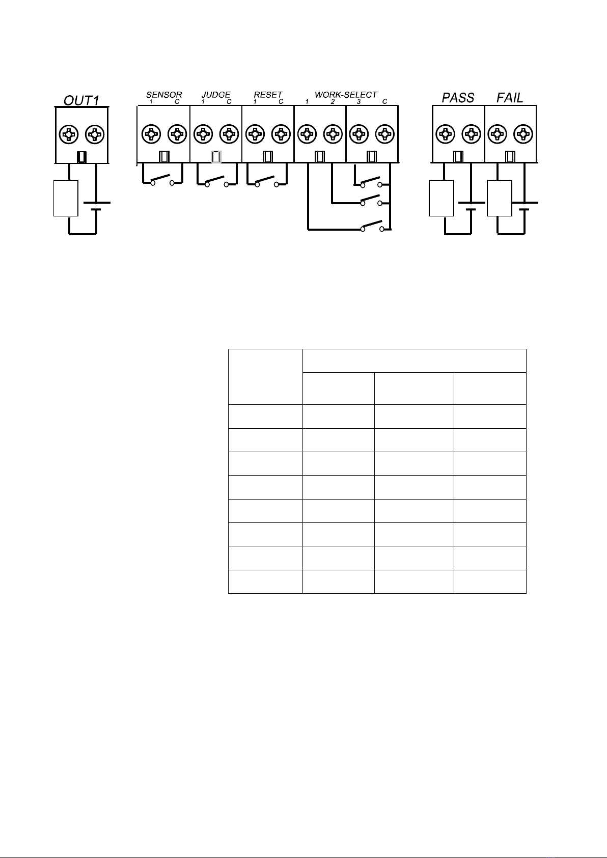
■ Input/output terminal Block
■ Input (non-voltage contact input)
(1) Sensor input 1 point +COM
(2) Judge input 1 point +COM
(3) Reset input 1 point +COM
(4) Work Select 3 point +COM
* Sensor/Judge/reset of an input signal can be changed from a cable input to a radio type by using 1 point type
transmitter (TW-800T).
■ Output (Photo-Mos relay output)
(1) PASS output 1 point
(2) FAIL output 1 point
(3) OUT output 1 point
* OUT1 output will be outputted if the signal from a transmitter is received. Output time follows a setup of a DIP
switch. since it synchronizes with buzzer sound when the signal from two or more transmitters is received, an
output may overlap and it may become at once.
Work
number
Work-Select input
1
2
3
1
OFF
OFF
OFF
2
ON
OFF
OFF
3
OFF
ON
OFF
4
ON
ON
OFF
5
OFF
OFF
ON
6
ON
OFF
ON
7
OFF
ON
ON
8
ON
ON
ON
Sensor (sensor) input
Judge (judgment) input
Reset (reset) input
Work Select
(Work selection) Input
PASS output
FAIL output
OUT1 output

TW-800R-EXC
10
■ Installation
(1) Please install this machine in the position which a transmitter to a prospect is good, is stabilized in an electric
wave, and can be received.
(2) Not to become a metal thing and parallel, please detach and install the antenna.
(3) Please supply the stable power supply with little change (DC24V).
Terminal box M3 (2 very)
Power supply voltage of operation DC24V (DC19 V-DC 28V)
* When you use with AC power supply, please use the AC/DC adaptor "ADB24050-C" of an option.
(4) Please wire an output terminal block (PASS/FAIL).
An output is a photo-MOS relay contact and between each terminal will be in a short circuit state with the output
ON. Please keep in mind that an internal circuit may be damaged when contact rated load is exceeded enough.
Rated load voltage AC/DC 30V
Rated load current 0.5A
Contact structure / composition MOS-FET/1a
(5) Please wire an input terminal block (SENSOR/JUDGE/RESET/WORK SELECT).
An input turns into a non-voltage contact input.

TW-800R-EXC
11
The antenna of a receiver should install so that there is no obstacle in the circumference of an antenna.
Since it is a diversity antenna type, there are two antennas, but please install the receiver so that both of
obstacles cannot be found in each circumference of an antenna.
Moreover, when you put in order and install two or more sets of receivers, please install so that antennas
separate 5 cm or more at least.
It is about 30-45 degree to the
direction of the front.
It is made to incline and installs.
It sees from the front and is 30-45
degree to the direction of outside.
It extends and installs.
Please detach at least 5 cm or more, and install.

TW-800R-EXC
12
Please do not carry out the following installation.
・This product serves as a minus (-) ground.
When the place to which these machines, such as an operator control panel and a pillar of a production line, are
attached is metal, a ground asks you for attachment, after confirming minus grounding or plus grounding.
Please keep in mind that the short circuit breaker of equipment may operate if it attaches with equipment of a plus
earth accidentally. When attached with equipment of a plus earth, I avoid the attachment to a metal thing, or
please give me the disposal of attaching on both sides of an insulator.
An operator control panel (metal thing) on
the back and antenna.It is parallel.
It is installed immediately near
the power line.
The antenna touches the operator
control panel (metal thing).
Antennas touch.

TW-800R-EXC
13
■Setting
This machine can perform the following setup with a DIP switch aside from a setup on a LCD screen.
Priority is given to a setup over a setup on a LCD screen by this switch.
●Output settin of a receiver
The relay output time of a receiver, double count prevention time, and buzzer operation can be set up with a DIP
switch. Please set up according to operation.
When you perform a setup and you make a change of a DIP switch, please be sure to turn OFF a power supply
and to perform it.
◆Buzzer ON/OFF
◆Relay output time (4 kinds)
◆Double count protect time (4 kinds)
*When “Relay output time”is set 50ms and “Double count protect time is set 10ms, Buzzer sounds 50ms.
Buzzer sounds 100ms ordinarily.
DIPSW
1
Buzzer does not sound
ON
Buzzer sounds
OFF
DIPSW
2
3
50ms
OFF
OFF
200ms
ON
OFF
400ms
OFF
ON
1S
ON
ON
DIPSW
4
5
10ms
OFF
OFF
200ms
ON
OFF
1S
OFF
ON
2S
ON
ON

TW-800R-EXC
14
◆Buzzer sounds Big/Small
◆Caution
While the receiver output relay output or while receiver is in double count protect time, receiver transmit the
busy signal to transmitter. Then receiver doesn’t move.
When the transmitter receives the busy signal, the Green LED of transmitter flashes 3 times.
According to setting relay output time and double count protect time, a difference is made for a transmitting
intervals. Please set depend on your situation.
<Receiver>
DIPSW
6
Small
ON
Big
OFF
Relay output time
Double count protect time
The time receiver cannot receive
(Receiver transmits BUSY signal to transmitter.)
The time receiver can receive

TW-800R-EXC
15
■Function
1. Judgment
This machine judges PASS/FAIL according to the mode and the contents
of a setting to be used. A judgment performs a display, a PASS/FAIL output, etc.
The outline which carries out a PASS/FAIL output with the kind to display is explained.
<The contents of a display of a judgment display>
The contents of a
display
Situation
Green lighting
PASS (work)
The state which all the selected contents of a work completed.
Blue lighting
PASS (every tool)
The state which the contents for every tool in the selected work completed.
Red light
FAIL
The state where FAIL was judged according to various conditions
Red blink
The state into which the count went in the state of OFF of a sensor input
when sensor input was ON setup. It is canceled in the sensor input ON.
Yellow lighting
When count alarm is ON setup, it is in the state which passed the set-up time.
If a count enters, a timer will be reset to zero and lapsed time will be again
measured inside. Since it is not a FAIL judging, a FAIL output is not
performed.
<PASS/FAIL>Output
■PASS output (every tool)
When the judgment type is chosen as the tool, PASS output is performed whenever each tool is completed with a
tightening. The output method is based on LED linkage (for 1 second: blue lighting is interlocked with), or an
output time set period (0.1 to 1.0 second).
■PASS output (work)
PASS output is performed when all the selected contents of a work are completed.
The output method is based on LED linkage (green lighting is interlocked with) or an output time set period (0.1 to
1.0 second).
■FAIL output and the reset method
FAIL output cause
The reset method
Count value remainder
error
When a count value amounts to "0", FAIL output is canceled and it changes to
a PASS output.
Sequence error
(Tool order mistake)
It can cancel only by reset input.
Over count error
It can cancel only by reset input.
Sensor error
It can cancel only by reset input.
* A sensor error is an error in case a count value is not 0 at the time of the
sensor OFF.
Judgment display
Table of contents
Other Herutu Conference System manuals

Popular Conference System manuals by other brands

AudioCodes
AudioCodes RX-PANEL quick guide

Grandstream Networks
Grandstream Networks GVC3212 Administration guide

Gas Clip Technologies
Gas Clip Technologies GCT IR Link Quick reference guide

Polycom
Polycom VSX 7000e Series Setting up

TANDBERG
TANDBERG VideoconferenceSystem quick start guide

Sony
Sony IPELA PCS-HG90 Connection Setup


