Herutu BN920 User manual

Wireless Call Systems
BN920
Instruction Manual V1.20
Please use this Instruction manual correctly on reading well.
Please keep it carefully to be able to read immediately, when required.


Table of Contents
1.Overview....................................................................................................................................... 1
1-1.Introduction........................................................................................................................... 1
1-2.Main Unit and Accessories.................................................................................................. 3
1-3.Safety Precautions (Be Sure to Read This)....................................................................... 4
1-4.General .................................................................................................................................. 6
1-5.System Configuration.......................................................................................................... 7
2.Specification................................................................................................................................ 8
2-1.General Specification ......................................................................................................... 8
2-2.Transmitter AN920T........................................................................................................... 8
2-3.Receiver BN920R/BNW920R.............................................................................................. 9
3.Part Names And Descriptions.................................................................................................. 10
3-1.AN920T ................................................................................................................................ 10
3-2.BN920R/BNW920R.............................................................................................................11
4.Drawing..................................................................................................................................... 12
4-1.AN920T............................................................................................................................... 12
4-2.BN920R/BNW920R............................................................................................................ 12
5. Settings ..................................................................................................................................... 13
5-1.Transmitter Setting............................................................................................................. 13
5-2.Display Setting.................................................................................................................... 16
6.Installation.................................................................................................................................. 19
6-1. Installation of Transmitter............................................................................................. 19
6-1-1.External Input............................................................................................................... 19
6-1-2. Input Circuit................................................................................................................. 19
6-2.Installation of Receiver...................................................................................................... 20
6-2-1. Input / Output Terminal Block................................................................................... 20
6-2-2.Output circuit.............................................................................................................. 22
7. Description of Operation......................................................................................................... 23
8.Speaker (Optional) .................................................................................................................... 26
8-1.Speaker Operation.............................................................................................................. 26
8-2.Dimensions of Receiver with Speaker............................................................................. 26
8-3.Sound Selection ................................................................................................................. 27
9. Keyboard................................................................................................................................... 29
9-1.Connect Keyboard Unit ..................................................................................................... 29
9-2.Name and Function of Keyboard Unit.............................................................................. 30
9-3.Operation of Keyboard Unit .............................................................................................. 30
10.After Service and Warranty................................................................................................... 31

BN920
1
1.Overview
1-1.Introduction
This instruction manual describes the information required for using this product including overview,
installation, and operation of this product. Read this manual carefully before using this product. Keep this
manual handy so that you can take it out immediately.
A wireless module "RN2903" built in this product obtained the transmitter approval of Federal
Communication Commission (FCC), CFR 47 Telecommunication, Part 15.212 Modular Transmitters, and the
module approval of Part15, Subpart C "International Radiators" based on the above approval.
The "RN2903" module is also approved for use in Canada according to the Radio Standards Specification
(RSS) RSS-210 and RSS-GEN of Industry Canada (IC).
■FCC Warning
■IC Warning
This equipment has been tested and found to comply with the limits for a Class B digital device, pursuant to part 15 of the
FCC Rules. These limits are designed to provide reasonable protection against harmful interference in a residential
installation. This equipment generates, uses and can radiate radio frequency energy, and if not installed and used in
accordance with the instructions, may cause harmful interference to radio communications. However, there is no
guarantee that interference will not occur in a particular installation. If this equipment does cause harmful interference to
radio or television reception, which can be determined by turning the equipment off and on, the user is encouraged to try
to correct the interference by one or more of the following measures:
• Reorient or relocate the receiving antenna.
• Increase the separation between the equipment and annunciator.
• Connect the equipment into an outlet on a circuit different from that to which the annunciator is connected.
• Consult the dealer or an experienced radio/TV technician for help.
This device complies with Industry Canada licenseexempt RSS standard(s). Operation is subject to the following two
conditions: (1) this device may not cause interference, and (2) this device must accept any interference, including
interference that may cause undesired operation of the device.
Le présent appareil est conforme aux CNR d'Industrie Canada applicables aux appareils radio exempts de licence.
L'exploitation est autorisée aux deux conditions suivantes: (1) l'appareil ne doit pas produire de brouillage, et (2)
'utilisateur de l'appareil doit accepter tout brouillage radioélectrique subi, même si le brouillage est susceptible d'en
compromettre le fonctionnement.

BN920
2
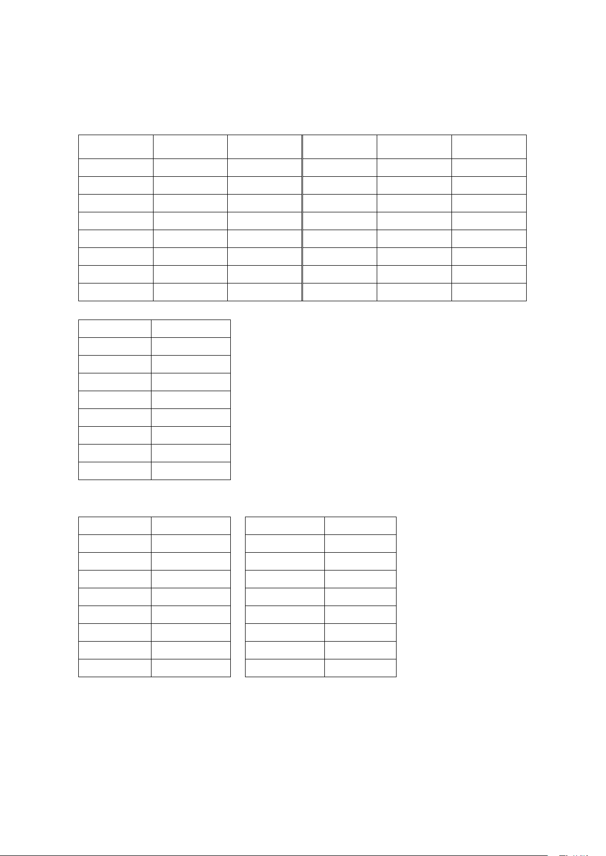
■External Antenna Types
Type
Gain(dBi)
Impedance
Sleeve Dipole
Under 6dBi
50Ω
1.Do not use this product for the application that may cause harm to human body or damage to other
devices and equipment.
Do not use this product near the devices that may malfunction due to radio waves emitted from this
product.
2.Disassembly or modification of the device having an approval is prohibited by the law.
3.This product is available only in Canada and USA.
4.Because the communication performance is changed depending on the surrounding environment, be sure
to confirm the communication is established before installation of this product and then use it.
Under Industry Canada regulations, this radio transmitter may only operate using an antenna of a type and maximum (or
lesser) gain approved for the transmitter by Industry Canada. To reduce potential radio interference to other users, the
antenna type and its gain should be so chosen that the equivalent isotropically radiated power (e.i.r.p.) is not more than
that necessary for successful communication.
Conformément à la réglementation d'Industrie Canada, le présent émetteur radio peut fonctionner avecune antenne d'un
type et d'un gain maximal (ou inférieur) approuvé pour l'émetteur par Industrie Canada.
Dans le but de réduire les risques de brouillage radioélectrique à l'intention des autres utilisateurs, ilfaut choisir le type
d'antenne et son gain de sorte quela puissance isotrope rayonnée équivalente (p.i.r.e.)
ne dépasse pas l'intensité nécessaire à l'établissement d'une communication satisfaisante.
This radio transmitter (identify the device by certification number, or model number if Category II) has been approved by
Industry Canada to operate with the antenna types listed below with the maximum permissible gain and required antenna
impedance for each antenna type indicated. Antenna types not included in this list, having a gain greater than the
maximum gain indicated for that type, are strictly prohibited for use with this device.
Conformément à la réglementation d'Industrie Canada,le présent émetteur radio peut fonctionner avecune antenne d'un
type et d'un gain maximal (ouinférieur) approuvé pour l'émetteur par Industrie Canada.
Dans le but de réduire les risques de brouillage radioélectrique à l'intention des autres utilisateurs, ilfaut choisir le type
d'antenne et son gain de sorte quela puissance isotrope rayonnée équivalente (p.i.r.e.)
ne dépasse pas l'intensité nécessaire à l'établissement d'une communication satisfaisante.
BN920
3
DC5V COM
-+
AN920T
MODE
UNIT
SET
CH
AN920T
ID
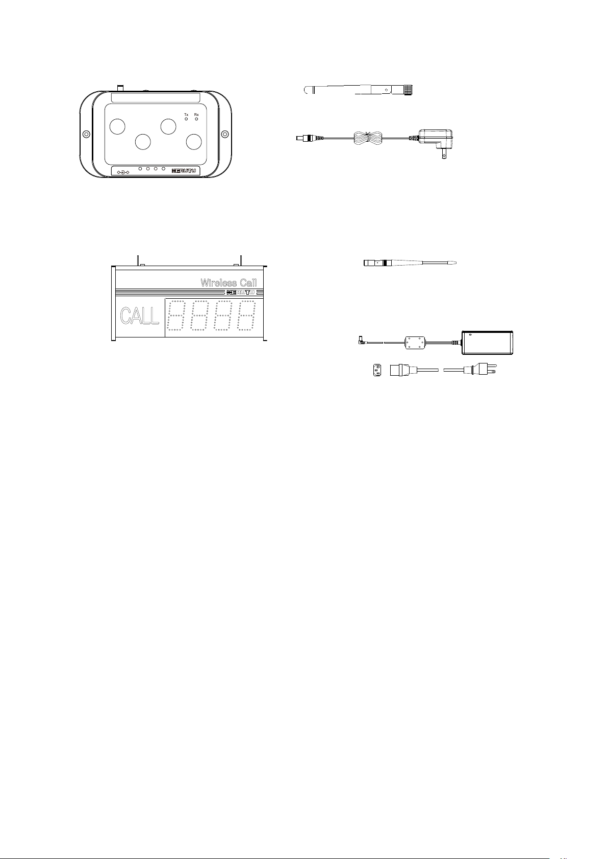
1-2.Main Unit and Accessories
■AN920T
■BN920R(Number Indicator Type)
※BNW-920R is same.
Receiver main unit BN920R
Antenna × 1
AC adapter ×1
(Cable: DC-code approx. 1.5 m + AC-cord
approx. 1.8 m)
Transmitter main unit
“AN920T” ×1
AC adapter ×1
Cable Approx. 1.5 m
Anntena ×1

BN920
4
1-3.Safety Precautions (Be Sure to Read This)
This section describes the matters to be observed in order to prevent harm to the users and other persons
and damages to the property.
■The following marks and displays classify and describe the extent of harm and damage caused by failing
to observe the display content and using this product wrongly.
This display column shows "a failure to do observe it could result in death or
serious personal injury".
This display column shows "a failure to do observe it could result in only the
personal injury or property damage".
■Common matters in handling
●Avoid using this product in the humid or dusty place. Dusts or water enters the product,
which may cause the fault, fire, or electric shock.
■Handling this product
●This product is the wireless communication equipment made of precision parts. Do not
disassemble or modify it. Or the accident or fault may occur.
■Handling this product
●Do not use this product for application that requires the extremely high reliability affecting
the human life.
●Do not use this product in the area which the radio wave reaches or not.
■Handling the power supply
Be sure to observe the followings in order to prevent the accidents such as heat generation, damage, or
ignition ofAC adapter and power cord.
●Do not place the AC adapter and power cord close to fire or insert them into fire. Or they
may be burst and ignited, resulting in the accident.
●Use the AC adapter and main body only at the specified power supply voltage in order to
prevent burst and ignition accidents.
●Do not use the AC adapter and main body at the location where they easily get wet. Or the
accidents including heat generation, ignition, or electric shock and faults may occur.
! Warning
! Caution
! Caution
! Warning
BN920
5
●Do not touch the AC adapter, main body, power cord, and outlet with wet hands. Or the
accident such as an electric shock may occur.
●Do not damage the power cord. Short-circuit or heat generation may cause fire or electric
shock.
●Do not use the power plug with dusts attached. Short-circuit or heat generation may cause
fire or electric shock.
●Do not give a strong shock to the AC adapter.
Or the accident or fault may occur.
●If you find a deformation in theAC adapter, do not use it.
Or the accident or fault may occur.
●Do not charge the main body at the location where the flammable gas is generated.
Or the ignition accident may occur.
●Never disassemble the AC adapter.
Or the accident or fault may occur.
■Never disassemble the AC adapter.
Remove the power plug from the outlet because it may cause fire and electric shock. Request the dealer
or our company to repair it.
●When smoke comes or there is a strange smell, immediately stop usage and remove the
power plug from the outlet because it may cause fire and electric shock. Request the dealer
or our company to repair it.
●If the cord is damaged, do not use it. Using the cord damaged continuously may cause fire
or electric shock.
■Reliability of wireless communication
As wireless communication has properties that are different from those of wired communication,
communication errors may occur due to the following.
・Exceeds the communication distance.
・Enters a dead zone.
・Interfered by strong jamming
If signals are often jammed, or being jammed leads to operational problems, stop using the systems and
restart using the systems after removal of the cause.
Radio waves may not be received due to various reasons other than the above. Please understand this
before using the systems.
*A dead zone is an area where the radio wave transmitted from the transmitter becomes extremely weak
due to radio waves reflected from walls or other objects.

BN920
6
1-4.General
BN920 series are wireless call systems using “LoRa Technology” for wireless communication.
The wireless call systems comprise a transmitter and a receiver. The transmitter transmits a code in
response to a button input or a terminal block input. The receiver receives signals from each transmitter, and
indicates numbers according to the input from the transmitter.
BN920 can be used for calling distant people and objects. Examples include operators notifying a shortage
of parts or an abnormal event in the assembly process.
The receiver has two display modes: 1-Digit mode and 2-Digit mode. The number of corresponding
transmitters is different depending on the display mode.
Display
modes
Device configuration
Indicator numbers that
can be indicated
simultaneously
Indicator numbers
1-Digit
1 receiver supporting max. 8
transmitters
Max. 4
1 –8
2-Digit
1 receiver supporting max. 64
transmitters
Max. 2
1 –64
1.The communication distance is approx.500m indoors and approx. 1km outdoors.
It can be extended further by setting the wireless output settings to “Long Range”.
2.Set a desired communication method. (With/Without answerback)
3.Wireless channels can be selected from 16 types, and code settings can be selected from 100 types.
Totally, a maximum of 160 configurations can be set.
4.The transmitter is equipped with 4 buttons (Orange/Red/Green/White) and 4 external inputs
(Orange/Red/Green/White). *Green(button and external input) is not available.
5.The included AC adapter is used for the power source for the transmitter and the receiver. (100 –240
VAC)
6.There are Single-sided indicator type and Double-sided indicator type.
7.An optional speaker enabling sound notifications can be installed on the receiver.

BN920
7
AN920T
MODE
UNIT
SET
CH
AN920T
ID
DC5V COM
-+
Tx Rx
AN920T
MODE
UNIT
SET
CH
AN920T
ID
DC5V COM
-+
Tx Rx
AN920T
MODE
UNIT
SET
CH
AN920T
ID
DC5V COM
-+
Tx Rx
AN920T
MODE
UNIT
SET
CH
AN920T
ID
DC5V COM
-+
Tx Rx
AN920T
MODE
UNIT
SET
CH
AN920T
ID
DC5V COM
-+
Tx Rx
AN920T
MODE
UNIT
SET
CH
AN920T
ID
DC5V COM
-+
Tx Rx
AN920T
MODE
UNIT
SET
CH
AN920T
ID
DC5V COM
-+
Tx Rx
AN920T
MODE
UNIT
SET
CH
AN920T
ID
DC5V COM
-+
Tx Rx
AN920T Max. 8nit : BN920R 1 unit
AN920T
MODE
UNIT
SET
CH
AN920T
ID
DC5V COM
-+
Tx Rx
AN920T
MODE
UNIT
SET
CH
AN920T
ID
DC5V COM
-+
Tx Rx
AN920T Max. 64 units : BN920R 1 unit
1-5.System Configuration
■1-Digit mode
■2-Digit mode
・・・・・・

BN920
8
2.Specification
2-1.General Specification
Item
Specification
A destination country
U.S.A., Canada
Standard
FCC : Part15 Sub Part C §15.247
IC : RSS-210/RSS-Gen
Frequency Band
903MHz~927MHz
Modulation Band
LoRa Technology
Antenna Power
Standard 3dBm(2.0mW) /Long Range 18.5dBm(70.79mW)
Modulation Speed
Approx.1170bps
Channel Step
1.6MHz
Antenna
External Dipole Antenna
Communication
Method
Half Duplex
2-2.Transmitter AN920T
Item
Specification
Indicator Element
1 Red LED (Rx)
1 Green LED (Tx)
Input(s)
4 Button (Orange/Red/Green/White(Off))
4 External-Input (Orange/Red/Green/White(Off))*1
Power Source
AC 100-240V (Using included AC Adapter)
Wattage.
7W
External Dimensions
(W × H × D)150 × 85 × 25 mm (5.9 × 3.3 × 1.0″)
Weight
Approx. 0.2kg (0.4lb)
Operating
Environment
Temperature:0-+50℃(32-124°F)
Humidity:20-85% (without condensation)
Switches
1 Switches (2-Position DIP each)
1 Switches (16-Position Rotary each) for Channel Setting
3 Switches (10P-Position Rotary each) for Set, Unit, ID
Included
1 AC adapter, 1 Antenna
*1:Available Wire Range Single Line:φ0.4mm(AWG26)~φ1.0mm(AWG18)
Twisted Line:φ0.3mm
2(AWG22)~φ0.75mm
2(AWG20)
Wire Diameter:φ0.18 more

BN920
9
2-3.Receiver BN920R/BNW920R
Item
Specification
Product type
BN920R
BNW920R
Indicator
Element
4-Digit Indicator, High Brightness Red
7-Segment LED
Single-Sided Indicator
Indicator Letter Dimensions
(H×W)110×60mm(4.3×2.4″)
4-Digit Indicator, High Brightness Red
7-Segment LED
Double-Sided Indicator
Indicator Letter Dimensions
(H×W)110×60mm(4.3×2.4″)
Output(s)
2 Open Collector Outputs (Max. Rated Load DC 35V 50mA)
2 Relay Output (Max. Related Load AC125V 0.5A / DC 24V 1A)
Input(s)
Optional Keyboard Unit (KE-2)
Power
Source
AC100-240V (Using included AC Adapter)
Wattage
Max.25W
Max.35W
External
Dimensions
(W×H×D)600 × 290 × 80mm (23.6×11.8×3.1″)
(except any protruding object such as an antenna)
Weight
Approx.5.5kg(17.6lb)
Approx.5.8kg(18.1lb)
Operating
Environment
Temperature:0~+50℃(32-122°F)
Humidity:85% or less (without condensation)
Setting
Switch
1 Switches (8-Position Dip each) for Channel, Unit, Display Modes
1 Switches (4-Position Dip each) for Set
Included
1 AC adapter, 1 Antenna
・The weight of the receiver with a speaker is approx.1.7kg heavier than that of a receiver without a speaker.

BN920
10
AN920T
MODE
UNIT
SET
CH
AN920T
ID
DC5V COM
-+
Tx Rx
Setting switch
0
1
3
4
5
6
7
8
9
2
0
1
3
4
5
6
7
8
9
2
0
1
3
4
5
6
7
8
9
2
0
1
2
3
4
5
6
7
8
9
A
B
C
D
E
F
1 2
ON
Antenna
Button switch
LED (Tx, Rx)
External contact input
terminal block
DC jack
Mounting
holes
3.Part Names And Descriptions
3-1.AN920T
Item
Description
Setting switch
Configures the settings for the channels, sets, units and IDs. and communication
settings.
Antenna
Connects the included antenna.
Mounting holes
Mounting hole of φ3.5 ×2
LED
Green LED (Tx) for transmitting and red LED (Rx) for receiving.
Button switch
Button switches in Orange/Red/Green/White.
Do not press more than one switch at the same time.
Input terminal block
for external contact
External inputs in Orange/Red/Green/White. The white button switch is for clearing
LEDs (Off). Input a no-voltage contact signal. Do not press more than one switch at the
same time.
DC jack
DC jack for connection of the included AC adapter

BN920
11
Power lamp
Power switch
SMA connector
Mounting
bracket
Signal line
Take-out hole
DC jack
LED indicator
Side panel
Option (with speaker) BN920R-MRD
BNW920R-MRD
Setting Label
3-2.BN920R/BNW920R
*BNW920R has a double sided LED indicator.
Item
Description
Mounting bracket
Use the mounting metal fittings for fixing the receiver.
SMA connector
Connects the included antenna.
Signal line take-out
hole
Connect the signal lines to the internal input/output terminal block by drawing them
through this takeout hole.
DC jack
DC jack for connection of the included AC adapter
Power lamp
Lamp for the power source. Lights up when the power source is switched on.
Power switch
Power switch of the main unit
LED Indicator
4-digit 7-segment high brightness LED. The number corresponding to the
transmitter ID received illuminates (or blinks).
Side panel
Remove the side panel to connect signal lines to the input/output terminal block or
configure channels/ indication mode/ unit/ set.
Setting label
Label showing factory default channel/ set/ unit.
e.g. “1-0-2”:Channel 1/ Set 1/ Unit 2
Speaker
An optional speaker can be installed on BN920R-MRD and BNW920R-MRD.
BN920
12
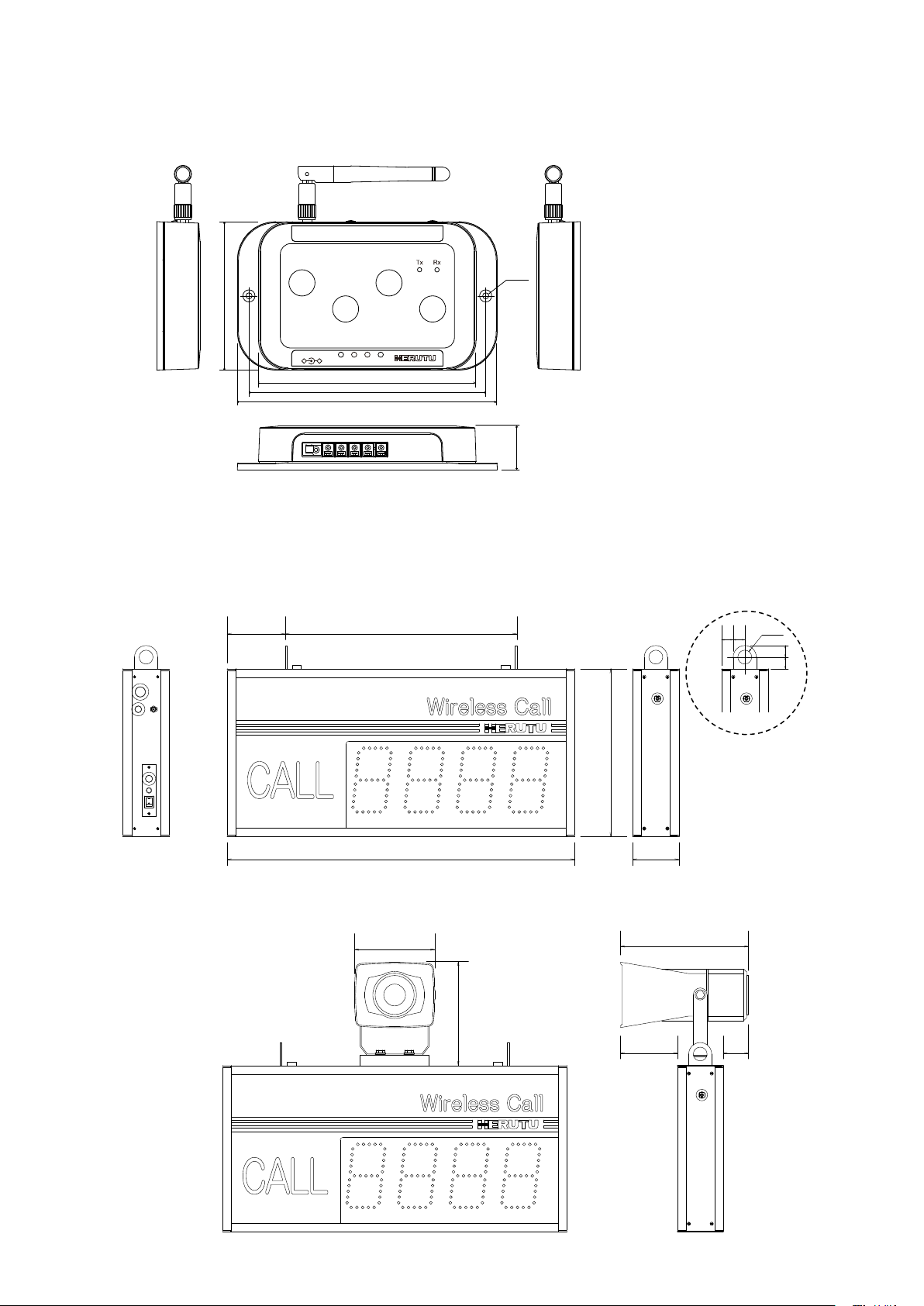
20 20
20
20
Φ24
290
80600
400100
99 44
182
223
140
DC5V COM
-+
AN920T
MODE
UNIT
SET
CH
AN920T
ID
125
150
85
25
136
2-φ3.5
4.Drawing
4-1.AN920T
4-2.BN920R/BNW920R
(BN920R-MRD/BNW-920R-MRD)

BN920
13
0
1
3
4
5
6
7
8
9
2
0
1
3
4
5
6
7
8
9
2
0
1
3
4
5
6
7
8
9
2
0
1
2
3
4
5
6
7
8
9
A
B
C
D
E
F
1 2
ON
RSW2
Set setting
5. Settings
Channel numbers (1-16)/Set numbers (1-8)/Unit numbers (1-8) can be set for the receiver.
Channel numbers (1-16)/Set numbers (1-8)/Unit numbers (1-8) and ID numbers (1-8) can be set for each
transmitter. The transmitter and receiver with the same Channel/ Set/Unit numbers can communicate with
each other. Determine the numbers to be indicated for each transmitter Unit and ID. Customers who
purchased the transmitter and receiver as a set do not need to configure the settings, as they are configured
at factory.
5-1.Transmitter Setting
For settings of the transmitter, remove the cover shown below and use the DIP switch and rotary switches.
■Communication settings
Set the communication method and antenna power.
< Communication method >
When setting the transmitter to “With answerback”, the receiver sends an answerback to the transmitter in
response to a signal from the transmitter. It is possible to confirm whether or not communication has been
performed when the receiver is placed where it cannot be seen from the transmitter.
When installing several receivers indicating the same status for the signal from one transmitter, set the
transmitter to “Without answerback”.
DIPSW1-1
Settings
OFF
With answerback
ON
Without answerback
< Wireless output setting >
The transmission output can be set to either standard or long range.
Standard 3dBm (2.0 mW): Communication distance Indoor Approx. 500 m Outdoor Approx. 1 km
Long range 18.5dBm (70.79 mW): Communication distance Indoor Approx. 1 km Outdoor Approx. 2 km
DIPSW1-2
Settings
OFF
Standard
ON
Long range
DIPSW1
Communication
setting
RSW4
ID setting
RSW3
Unit setting
RSW1
Channel setting
Remove the cover.
BN920
14
■Channel / Set / Unit / ID
Match the settings for Channel/Set/Unit with those of the receiver to communicate with. For the settings of
the receiver, see the configuration label affixed to the lower part of the receiver. The indicator to be
illuminated is determined by ID setting.
< Channel >
RSW1
Channel
Frequency
(MHz)
RSW1
Channel
Frequency
(MHz)
1
1
903.0
9
9
915.8
2
2
904.6
A
10
917.4
3
3
906.2
B
11
919.0
4
4
907.8
C
12
920.6
5
5
909.4
D
13
922.2
6
6
911.0
E
14
923.8
7
7
912.6
F
15
925.4
8
8
914.2
0
16
927.0
<Set>
RSW2
Set
1
1
2
2
3
3
4
4
5
5
6
6
7
7
8
8
<Unit ><ID>
RSW3
Unit
RSW4
ID
1
1
1
1
2
2
2
2
3
3
3
3
4
4
4
4
5
5
5
5
6
6
6
6
7
7
7
7
8
8
8
8

BN920
15
The numbers indicated on the receiver in the 1-Digit mode or 2-Digit mode are as described below.
1-Digit: ID numbers are indicated.
2-Digit: The numbers to be indicated are as below.
Unit
ID
Indicator
Number
Unit
ID
Indicator
Number
Unit
ID
Indicator
Number
Unit
ID
Indicator
Number
1
1
1
2
1
9
3
1
17
4
1
25
1
2
2
2
2
10
3
2
18
4
2
26
1
3
3
2
3
11
3
3
19
4
3
27
1
4
4
2
4
12
3
4
20
4
4
28
1
5
5
2
5
13
3
5
21
4
5
29
1
6
6
2
6
14
3
6
22
4
6
30
1
7
7
2
7
15
3
7
23
4
7
31
1
8
8
2
8
16
3
8
24
4
8
32
Unit
ID
Indicator
Number
Unit
ID
Indicator
Number
Unit
ID
Indicator
Number
Unit
ID
Indicator
Number
5
1
33
6
1
41
7
1
49
8
1
57
5
2
34
6
2
42
7
2
50
8
2
58
5
3
35
6
3
43
7
3
51
8
3
59
5
4
36
6
4
44
7
4
52
8
4
60
5
5
37
6
5
45
7
5
53
8
5
61
5
6
38
6
6
46
7
6
54
8
6
62
5
7
39
6
7
47
7
7
55
8
7
63
5
8
40
6
8
48
7
8
56
8
8
64
BN920
16
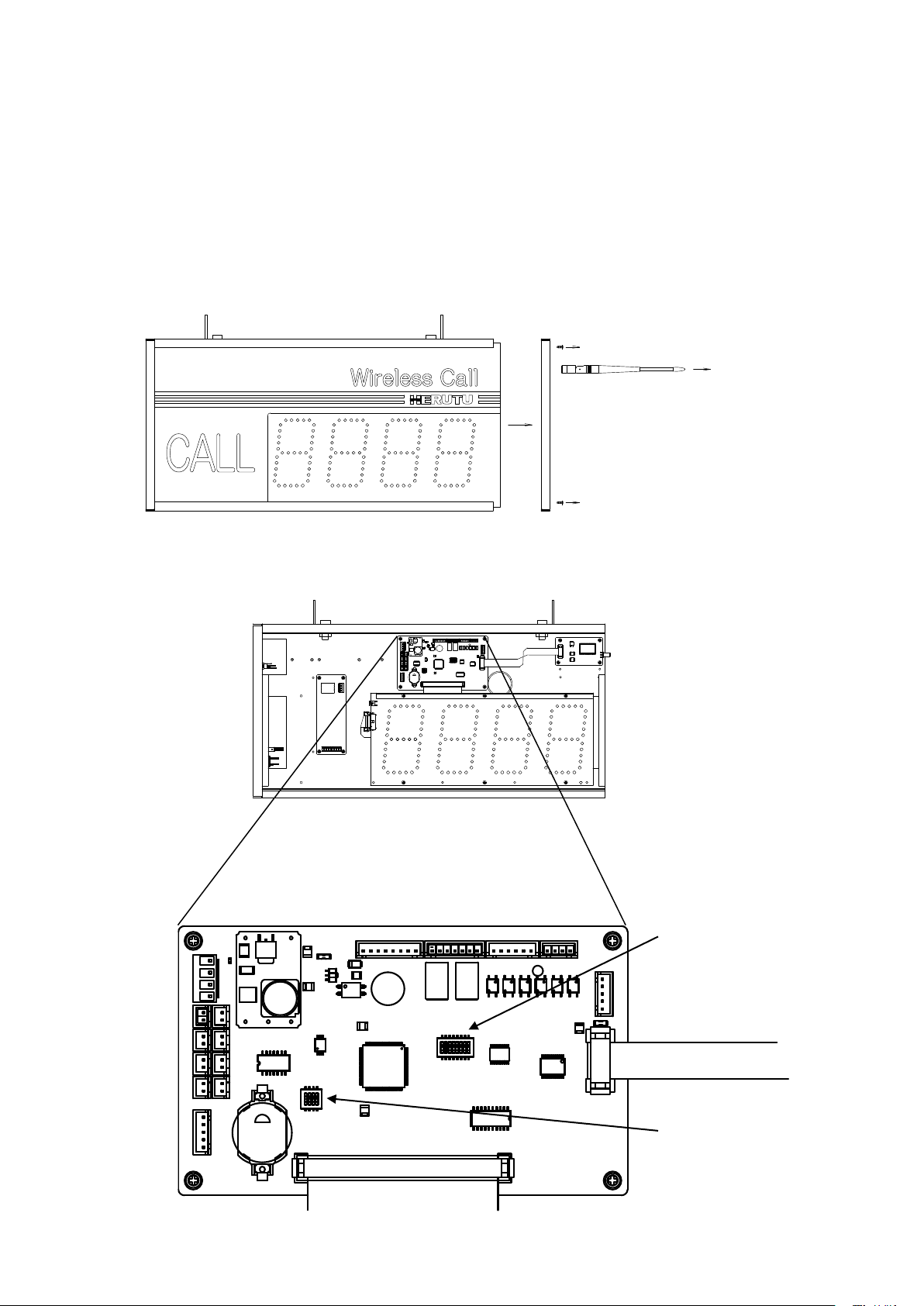
As the CPU board is in the front, remove the front acrylic sheet by sliding it out.
Inside of the receiver (Surface)
CPU board
DIPSW1(8-position)
DIPSW2(4-position)
5-2.Display Setting
Set the receiver using the DIPSW1 (Dip Switch 1) and the DIPSW2 (DIP switch 2) on the CPU board inside
the receiver. Set the antenna vertical to the side panel and remove the screws (4) securing the side panel.
Move the side panel so that it does not get caught in the antenna and remove the side panel.
When you set and change the setting of receiver, please set it after turning off the power.
Customers who purchased the transmitter and receiver as a set do not need to configure the settings, as
they are configured at factory. Label showing factory default channel/ set/ unit.

BN920
17
■Channel / Set / Unit
Configure the settings of Channel/Set/Unit to match those of the transmitter to communicate with.
< Channel > DIPSW1(1-4) *”Channel” is set by DIPSW1(8-position)
Channel
DIPSW1
1~4
Channel
DIPSW1
1~4
1
2
3
4
1
2
3
4
1
OFF
OFF
OFF
OFF
9
OFF
OFF
OFF
ON
2
ON
OFF
OFF
OFF
10
ON
OFF
OFFF
ON
3
OFF
ON
OFF
OFF
11
OFF
ON
OFF
ON
4
ON
ON
OFF
OFF
12
ON
ON
OFF
ON
5
OFF
OFF
ON
OFF
13
OFF
OFF
ON
ON
6
ON
OFF
ON
OFF
14
ON
OFF
ON
ON
7
OFF
ON
ON
OFF
15
OFF
ON
ON
ON
8
ON
ON
ON
OFF
16
ON
ON
ON
ON
<Set>DIPSW2 1~3*”Set”is set by DIPSW2(4-position)
Set
DIPSW2
1-3
1
2
3
1
OFF
OFF
OFF
2
ON
OFF
OFF
3
OFF
ON
OFF
4
ON
ON
OFF
5
OFF
OFF
ON
6
ON
OFF
ON
7
OFF
ON
ON
8
ON
ON
ON
<Unit>DIPSW1 6~8*”Unit” is set by DIPSW1(8-position)
Unit
DIPSW2
6-8
6
7
8
1
OFF
OFF
OFF
2
ON
OFF
OFF
3
OFF
ON
OFF
4
ON
ON
OFF
5
OFF
OFF
ON
6
ON
OFF
ON
7
OFF
ON
ON
8
ON
ON
ON
The settings for the Units are invalid in the 2-Digit mode.
Table of contents
Other Herutu Conference System manuals

Popular Conference System manuals by other brands

Jabbla
Jabbla Tellus 6 operating instructions

LY International Electronics
LY International Electronics H-9500 Series Installation and operating manual

RADVision
RADVision Scopia XT1000 user guide

AT&T
AT&T MERLIN LEGEND Reference

Polycom
Polycom RealPresence Group Series setup sheet

ProSoft Technology
ProSoft Technology AN-X4-AB-DHRIO user manual

Sony
Sony PCS-I150 Operation guide

Middle Atlantic Products
Middle Atlantic Products VTC Series instruction sheet

AVT
AVT MAGIC AC1 Go Configuration guide

Prentke Romich Company
Prentke Romich Company Vanguard Plus Setting up and using

Speakerbus
Speakerbus iD 712 user guide

Trelleborg
Trelleborg SafePilot CAT PRO user guide


