2
Contents
Usage for the intended purpose ..............................................................................................................5
Safety Note.............................................................................................................................................5
Danger ...................................................................................................................................................5
ATEX (Atmosphère Explosible).................................................................................................................5
Note on the Declaration of Conformity / Declaration by the Manufacturer ..........................................5
Important Notes
Page
Explanatory Notes
Scope of supply......................................................................................................................................6
Description .............................................................................................................................................6
Function ............................................................................................................................................. 6, 7
Installation notes ..................................................................................................................................16
Attention...............................................................................................................................................16
Note .....................................................................................................................................................16
Mounting conductivity transmitter.........................................................................................................16
Installation
Electrical Connection
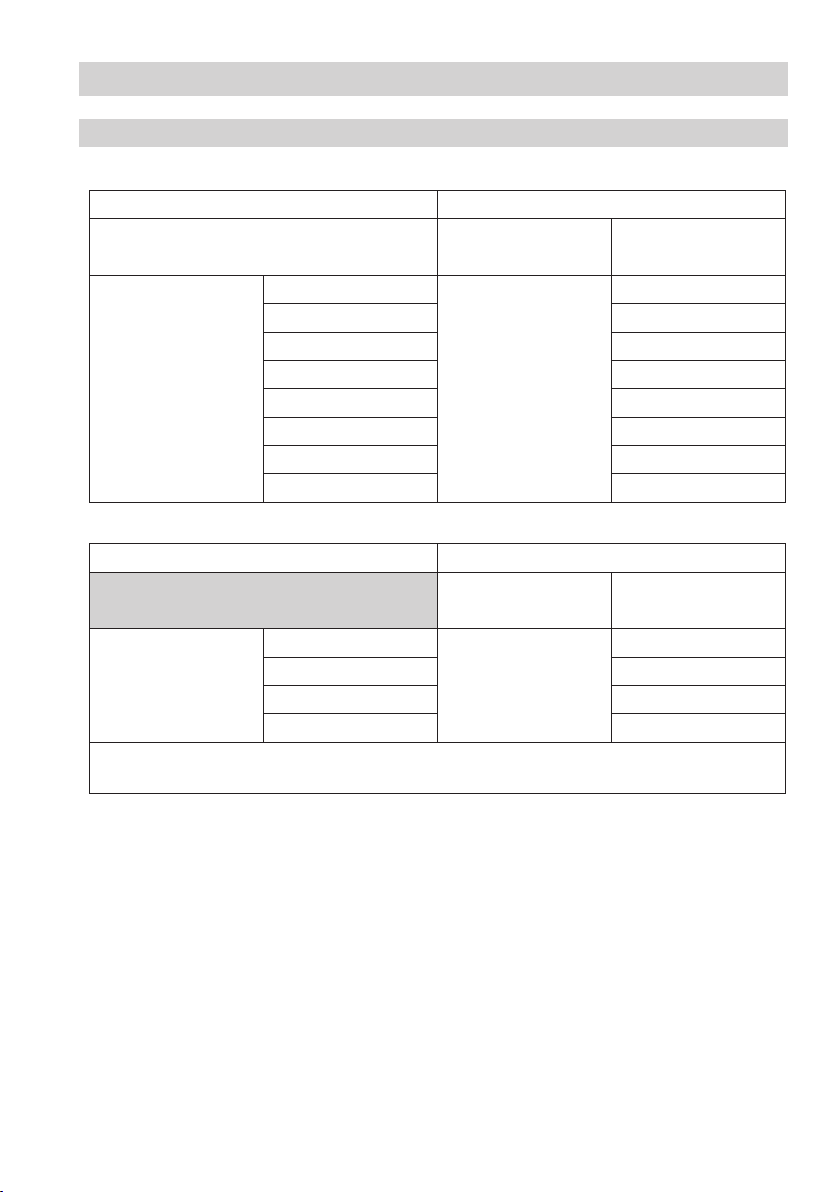
Technical Data
LRGT 16-1, LRGT 16-2, LRGT 17-1..................................................................................................... 8, 9
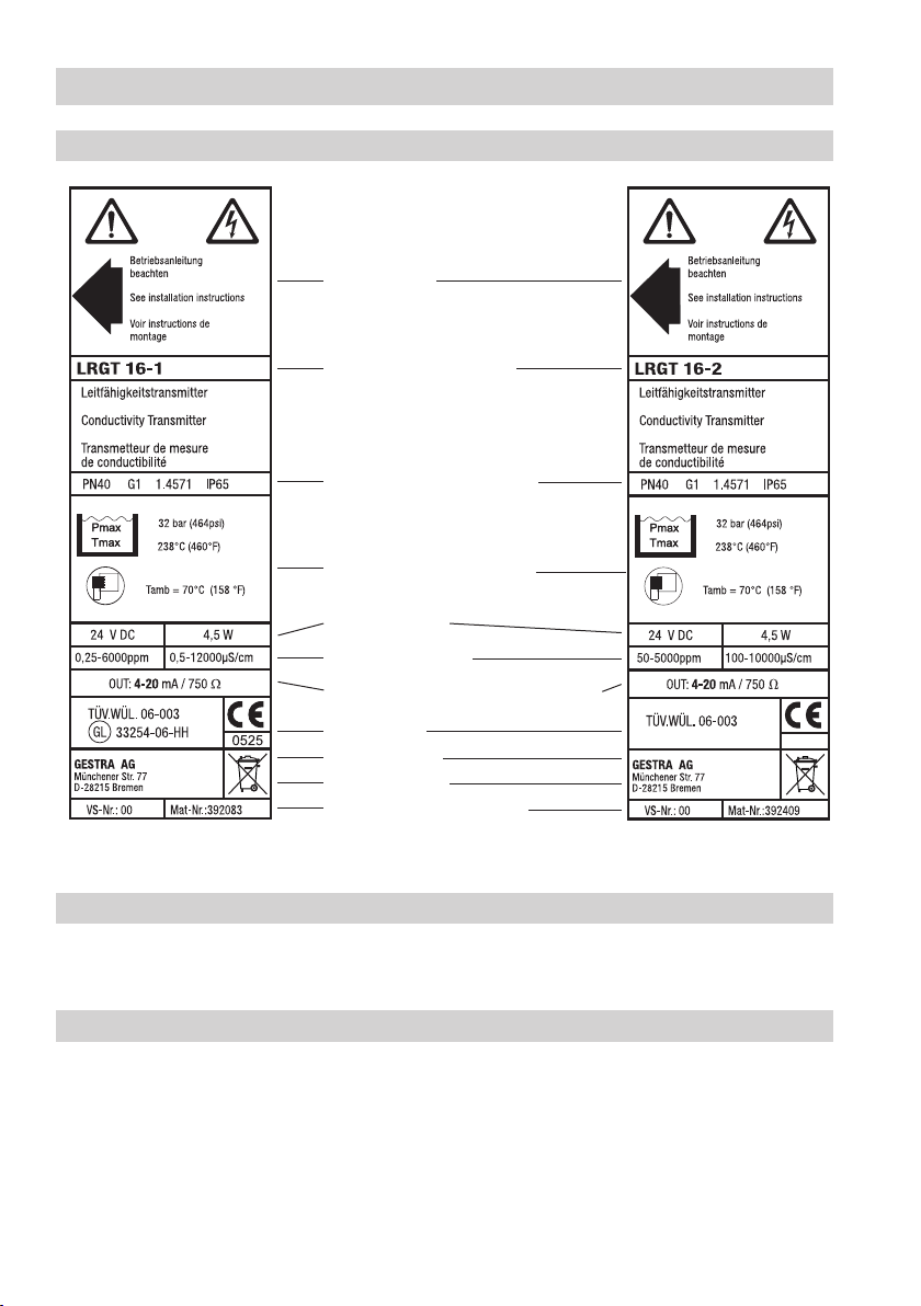
Name plate / marking ...........................................................................................................................10
Corrosion resistance.............................................................................................................................10
Sizing ...................................................................................................................................................10
Dimensions...................................................................................................................................11 – 13
Key.......................................................................................................................................................15
Examples of installation .................................................................................................................. 17, 18
Key.......................................................................................................................................................18
Tools.....................................................................................................................................................18
Examples of Installation
LRGT 16-1, LRGT 16-2, LRGT 17-1.......................................................................................................14
Key.......................................................................................................................................................15
Functional Elements
LRGT 16-1, LRGT 16-2, LRGT 17-1.......................................................................................................19
Connecting the conductivity transmitter..........................................................................................19, 20
Key.......................................................................................................................................................20
Safety power supply unit for LRGT 16-1, LRGT 16-2, LRGT 17-1...........................................................21
Tools ....................................................................................................................................................21
Wiring diagram for conductivity transmitter LRGT 16-1, LRGT 17-1 ......................................................21
Wiring diagram for conductivity transmitter LRGT 16-2.........................................................................22