Herz HD 240 User manual
HERZ
Herz Hochdruckgebläse - Betriebsanleitung
Herz high-pressure blowers – Operating instructions
Ventilateurs haute pression Herz – Notice d’utilisation
Ventilatori ad alta pressione Herz – Instrizioni per l’uso
Herz Oldalcsatornás légellátó - Használati útmutató
HERZ
Herz GmbH
Biberweg 1, D-56566 Neuwied
Telefon +49 (0)26 22 / 8 10 86
Telefax +49 (0)26 22 / 8 10 80
Internet http://www.herz-gmbh.com
E-mail: [email protected]

HERZ GmbH
BA HD240 02/2010 V.3.0 Rev. 2.0 9
INDEX
1. GENERAL INSTRUCTIONS 10
1.1 CONDITIONS OF USE 10
1.2 STORAGE AND SHIPPING 10
1.3 INSTALLATION 10
1.3.1 FJET BLOWER - EXHAUSTER 10
1.3.2 ELECTRIC MOTOR 11
1.3.2.1 CURRENT MEASUREMENT 11
1.4 COMMISSIONING 11
1.5 OPERATING ADJUSTMENTS 11
1.6 MAINTENANCE 11
2. INSTALLATION SKETCHES 12
2.1 PRESSURE SERVICE 12
2.2 PARALLEL PRESSURE SERVICE 12
2.3 SERIES PRESSURE SERVICE 12
2.4 VACUUM SERVICE 12
2.5 PARALLEL VACUUM SERVICE 12
2.6 GAS TRANSFER 12
2.7 LIST ACCESSORIES 12
3. INTERNAL CLEANING INSTRUCTIONS 13
3.1 CLEANING INSTRUCTIONS 13
3.2 REPLACEMENT SOUND-ABSORBING PANELS 13
4. SILENCER HOUSING MOUNTING INSTRUCTIONS 14
4.1 USING THE 90° MANIFOLD KIT TYPE CK 14

HERZ GmbH
10 BA HD240 02/2010 V.3.0 Rev. 2.0
1. GENERAL INSTRUCTIONS
CAUTION
The ‘FJET’ blowers - exhausters have been
designed and manufactured for use in an
industrial environment, operated by qualified
personnel and as a unit to be incorporated in a
machine, which conforms to the CE Machinery
Directive.
The ‘FJET’ blowers - exhausters, like all
machinery and equipment with live and moving
parts, can be a source of serious hazards unless
properly used and protected.
The user is committed to ensure that:
All handling, assembly, installation, connection,
maintenance and repair operations are
undertaken by qualified personnel. Such people
who by their background, training and experience
as well as through their knowledge of statutory
regulations, legislation, safety measures and
operating conditions are able to carry out any
necessary steps avoiding all possible risks to
health and damage.
Such personnel should have received all the instructions
and information, including any local legislation, and will
follow them during the performance of any operation.
It shall be forbidden for unqualified personnel to carry out
any operation, even indirectly, on the machines and
equipment.
During the installation, all the prescribed working
conditions, including any possible local requirements, shall
be observed. Additionally it is forbidden to put the unit in
service before the machines of which they are a part are
declared to conform to the CE Machinery Directive.
The user must be aware that in operation:
• • the surface temperatures can reach 160°C;
• • the unit cannot contain high internal pressures, no
greater than Ps referred to in SN 1867;
• • there is small loss of the fluid handled;
• • the level of noise may be unacceptable in certain
applications.
1.1 CONDITIONS OF USE
The ‘FJET’ blowers - exhausters are designed for the continuous
movement of air or non-explosive, non-hazardous and
nonflammable gases and for service in non-explosive
environments.
Solid particles, however small, including dirt can cause serious
damage; therefore it is essential that such substances should be
removed from the gas by suitable filters upstream of the inlet.
(Units which do not have an adequate filter ARE NOT
COVERED BY THE GUARANTEE).
The maximum driving pressure must never be exceeded (∆pmax
of SN 1867).
UNDER NO CIRCUMSTANCES OPERATE THE UNIT WITH
THE GAS INLET OR OUTLET CLOSED. IN PARTICULAR
THIS APPLIES TO THE UNITS WITH THE CAPACITY FOR
HIGHER DRIVING PRESSURES.
Protect the units with an appropriate safety valve.
The performance characteristics are liable to variations due to
the following factors:
• • Differences of the suction or discharge pressures from the
reference conditions (1013 mbar);
• • Operation in a system with both a low suction pressure
and a high back pressure;
• • Operation with a gas at a different temperature or of a
different specific gravity from the reference data (1.23
kg/m3; 15 °C);
• • Variations in the rotational velocity of the fan with respect
to the reference value.
Both the gas inlet temperature and the ambient temperature
must be in the range of -15°C to +40°C.
At the same time, ensure that the unit has good ambient
ventilation, especially when subjected to severe operating
conditions. A unit subjected to frequent starting or to high
ambient temperatures may be prone to overheating and in such
cases further information should be requested. Similarly, where
flammable gases may be present, information must be
requested for alternative models certified for the Ex.
environment.
1.2 STORAGE AND SHIPPING
Store the unit in a dry place, preferably in original packaging.
Do not remove the protection plugs from the ports. Avoid
stacking anything on top of the packaging.
To move the packed boxes, use the largest pallet or support
base possible to obtain the maximum stability.
On all occasions handle the units with care and avoid sudden
impacts. Lifting eyes are provided to unpack units weighting
more than 25 kg. (The weight of the unit is M in SN 1867).
1.3.1.1 INSTALLATION
1.3.2 ‘FJET’ BLOWER – EXHAUSTER
It is important that the unit is installed in a well-ventilated
environment where the temperature does not exceed 40°C.
If outside, protect the unit from direct sunlight and avoid the
possibility of water collecting in the external crevices especially
when installed with the axis vertical.
IMPORTANT!
Ingress of foreign matter, however small, will cause serious
damage.
Such matter includes dust, sand, masonry debris, impurities in
the tubes, cutting burrs or filings, welding or soldering slag and
splatter, metal burrs and any residues from sealing and making
the tube connections.
The unit can be mounted with the axis in any position. As
supplied, the unit is balanced and will not transmit vibrations,
however it is recommended that it be mounted on vibration
damping supports. To connect the accessories, remove the
flanges from the unit and then seal and tighten.
Do not over tighten remembering that the operating pressures
are low.
Tube connections must be made with flexible couplings.
Avoid using rigid couplings, which will induce stress and cause
harmful vibrations.
Remember to protect the inlet with suitable filters.
If it is necessary to regulate the flow, install a bypass valve (refer
to section 1.5).
Only remove the plugs on the ports when making the final
connections.

HERZ GmbH
BA HD240 02/2010 V.3.0 Rev. 2.0 11
Select the tube size and the couplings to minimize the pressure
drop, in particular:
• Do not use tubing of a smaller diameter than the ports of the
unit; When installing units in parallel, size the manifold and
main conduit accordingly;
• Utilise large radius bends and avoid using elbows;
• Avoid using valves which have a reduced orifice relative to
the general system; Use swing check valves (utilising
lightweight discs) which have the lowest pressure drop,
rather than spring loaded check valves;
• For oxygenation select low loss diffusers (lowest pressure
drop) and note that the pressure drop across plugs and
porous membranes will increase over time due to
progressive clogging.
A safety relief valve should be installed to avoid overloading the
unit as a result of pressure differential variations.
Make the electrical connections to the motor and check the
direction of rotation before connecting the conduit.
The ‘FJET’ blowers - exhausters are already supplied as
standard with silencers in the suction and exhaust ports (the
noise levels Lp and Lw, with piped inlet and outlet flow, are
detailed in SN 1867).
For operation into free air (either suction or discharge) the free
flow noise can be muffled with additional silencers.
In every situation avoid installing the unit on a structure, which
can transmit or amplify any noise (tanks, sheet metal etc.).
Installation sketches - please refer to next page.
Further information should be requested regarding additional
noise reduction by installing the unit in soundproof enclosures.
1.3.2 ELECTRIC MOTOR
WARNING
BEFORE UNDERTAKING ANY OPERATION ENSURE THAT
THE UNIT IS DISCONNECTED FROM THE ELECTRICITY
SUPPLY.
The electric motor has been selected for service in an ambient
temperature between -15°C and +40°C at an altitude no higher
than 1000 m. Ensure that the information on the nameplate is
consistent with the supply voltage and frequency.
Variations in the supply voltage up to ± 10% are acceptable.
Outside the normal operating conditions the motor cannot deliver
full power and problems can arise with starting, especially for
single-phase motors.
Make the electrical connections referring to the wiring diagram in
the terminal box, connecting an earth cable of adequate capacity
to the earth terminal.
The fuses are designed only for short circuit protection and not
to safeguard the motor. Therefore overload cut-outs
(temperature or current) are essential to guard against the risk of
overloads on the motor --- for example failure of one line in a
three phase supply, an excessively high start up frequency,
unacceptable variations in the supply voltage, stalled rotor, etc..
Set the overload cutouts at the nominal current specified on the
nameplate.
The fuses should be rated for the peak currents or use “slow
blow” fuses especially in applications of direct starting.
THE ENTIRE GUARANTEE SHALL CEASE TO APPLY WHEN
INADEQUATE PROTECTION IS PROVIDED.
1.3.2.1 CURRENT MEASUREMENT
The current drawn refers to normal operating conditions.
Departures from the nominal operating conditions can result in
variations of 10%.
There can be small differences in the measured value of each
phase. These are tolerable up to a maximum deviation of 9%
(ref. IEC 34-1).
1.4 COMMISSIONING
To commission the unit:
• Set the operating pressure or vacuum using a suitable
gauge.
• Check the relieving pressure of the safety valve.
• Measure the current drawn by the motor and verify that it is
within the limit stated on the name plate (refer to Para.
1.3.2.1).
• Adjust the overload cutouts accordingly.
• After one hour's operation, repeat the current
measurements and verify that they are still within the stated
limits.
1.5 OPERATING ADJUSTMENTS
The ‘FJET’ blowers - exhausters will automatically generate the
driving pressure required at the point of use.
Since the power absorbed and the operating temperature is
primarily a function of the driving pressure, it is possible that
these can exceed the permitted operating conditions for the unit.
Frequently the pressure losses of the tubing are overlooked as
the major factor determining the driving pressure.
The driving pressure can be reduced by eliminating all possible
obstructions and restrictions in the flow path. If it is still too high,
the flow can be reduced by installing a bypass valve.
Never choke the flow by throttling the suction or the discharge.
1.6 MAINTENANCE
After every 10-15 days of use clean the cartridge filter. Replace
the cartridge frequently in dusty environments.
A dirty filter will create a strong suction resistance and
consequently a higher driving pressure, a higher operating
temperature and an increase in the absorbed power.
Check that the driving pressure does not change over time.
It is important that a unit in service is subjected to periodic
inspections by qualified personnel to insure against failures,
which, directly or indirectly, could cause damage.
Departures from the normal operating conditions (e.g. a rise in
the absorbed power, unusual operating noises, vibrations, etc.)
are a sign of abnormal operation, which can lead to failure.
In the event of difficulties please contact CBI or the relevant
sales agent.
Please note that repairs undertaken by a third party will
invalidate the guarantee.
Periodically remove any surface deposits which otherwise can
cause the operating temperature to rise.
Commitments, agreements or legal relationships are
governed by the corresponding sales contract. The above
items are in no way limited by the contents of this manual.
The quality of the materials and of the workmanship is
guaranteed as set out by the standard conditions of sales.
The guarantee is not valid for the following: damage
incurred during transport; inadequate storage; faulty
installation; incorrect use; exceeding performance limits;
electrical or mechanical miss-use.
Store the packaging for possible future use.
HERZ GmbH
12 BA HD240 02/2010 V.3.0 Rev. 2.0
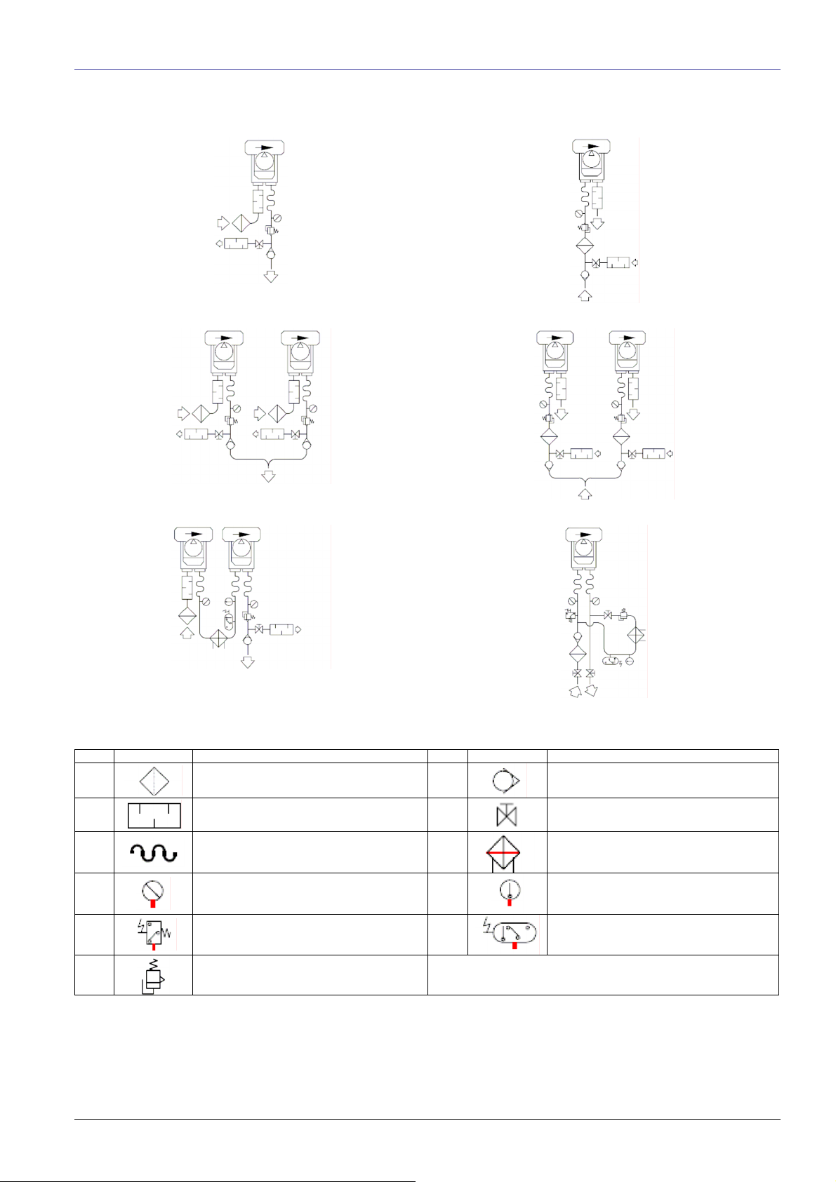
2. INSTALLATION SKETCHES
2.1 PRESSURE SERVICE 2.4 VACUUM SERVICE
2.2 PARALLEL PRESSURE SERVICE 2.5 PARALLEL VACUUM SERVICE
2.3 SERIES PRESSURE SERVICE 2.6 GAS TRANSFER
2.7 LIST ACCESSORIES
Item Denomination Item Denomination
1 Filter – Inline filter 7
Check valve
(2) Silencer 8
Valve
3 Flexible coupling (9)
Cooler
4 Pressure – Vacuum gauge (10)
Thermometer
5 Pressure – Vacuum switch (11)
Temperature switch
6
Relief valve (x) IF NECESSARY
Other manuals for HD 240
1
Table of contents
Other Herz Blower manuals


Popular Blower manuals by other brands

Lithium Earthwise
Lithium Earthwise LB20024 Operator's manual

EINHELL
EINHELL GE-CL 36 Li E Original operating instructions

EINHELL
EINHELL VENTURRO 18/210 operating instructions

Troy-Bilt
Troy-Bilt 657 Operator's manual

Weed Eater
Weed Eater VS2000BV instruction manual

KRAUSMANN
KRAUSMANN U37020-00 Operation manual


