HES HS0753 User manual

*** MENU ***
CHAPTER 1 SAFETY SUMMARY
1.0 Introduction ............................ HS0753-1-01
1.1 Safety During Installation ...............HS0753-1-01
1.2 Safety During Operation ..................HS0753-1-02
1.3 Safety During The Maintenance ............HS0753-1-02
1.4 Safety When Using Adhesive And Solvents ..HS0753-1-03
CHAPTER 2 EQUIPMENT FAMILARIZATION
2.0 Introduction .............................HS0753-2-01
2.1 Description Of The Machine Character .....HS0753-2-02
2.2 Specification Summary ....................HS0753-2-05
2.3 Functional Description Of Standard .......HS0753-2-05
2.3.1 Power System .......................HS0753-2-05
2.3.2 Hydraulic System ...................HS0753-2-05
2.3.3 Electrical Power System ...........…HS0753-2-06
CHAPTER 3 OPERATION INSTRUCTIONS
3.0 Introduction ............................ HS0753-3-01
3.1 Safety Precaution ........................HS0753-3-01
3.2 The Function Of Control Panel ............HS0753-3-02
3.3 Daily Operation ..........................HS0753-3-05
3.3.1 Turn On Procedure ..................HS0753-3-05
3.3.2 Shut-Off Procedure .................HS0753-3-06
CHAPTER 4 DISASSEMBLY AND REPAIR
4.0 Introduction .............................HS0753-4-01
4.1 Safety Precaution ........................HS0753-4-01
4.2 The Replacement Of The o-ring Between The
Nozzle Device & Adhesive Tank ............HS0753-4-01
4.3 Disassemble And Repair Of Quick Relieve
Valve ....................................HS0753-4-03

CHAPTER 5 TROUBLESHOOTING
5.0 Introduction ............................HS0753-5-01
5.1 Safety Precautions ......................HS0753-5-01
5.2 Troubleshooting Of Mechanical And
Electrical Parts ........................HS0753-5-01
CHAPTER 6 THE PARTS FIGURE COLLECTION
6.0 Introduction ............................HS0753-6-01

CHAPTER 1 SAFETY SUMMARY
1.0 Introduction
This chapter, intended as an introduction to the installation,
operation and maintenance of HS0753 Pressure-Keeping Type Hot
Melt Applicator, sets out the safety rules to be observed for
preventing risk both to personnel and to the equipment.
This risk prevention rules may be classified as follow:
1. Safety during installation.
2. Safety during equipment operation.
3. Safety during maintenance.
4. Safety during use of hot melt solvents.
Failure to follow these recommendations may result in person-
nel injury from burns or electrocution and/or equipment and
property damage.
1.1 Safety During Installation
1. Establish correct and effective ground connection for en-
tire apparatus, without such connection, every element of
the apparatus even those are apparently insulated become a
potential conductor and pose a risk of electrical shock.
2. Check that the power cords and their insulation are corre-
ctly dimensioned for the load constituted by the apparatus
complate with all its accessories.
3. Ensure that a switch with a thermal safety cut-off is in-
stalled between the apparatus and the primary generator.
4. Always operate the apparatus in accordance with the recom-
mended current and voltage.
If the apparatus is operate at voltages and currents other
that recommended this may create potential fire risk.
HS0753-1-01 930906

1.2 Safety During Operation
1. Do not operate the equipment near volatile or otherwise ex-
plosive gases or materials.
2. Do not operate the equipment without the covers, panels and
safety guards properly installed.
3. Do not operate the equipment at a temperature above 50℃ or
below 0℃.
4. If the applicator nozzle device unshielded from the wind.
Rapid heat dissipation due to air movement across the noz-
zle tip may cause operational problems.
5. Do not use the equipment as a ladder or stepping stool.
6. Use only the metal base when attempting to lift or move an
applicator. Do not use equipment covers, doors, panels, as
braces or grips.
1.3 Safety During The Maintenance
The main precautions to be adopted when carrying out mainten-
ance are:
1. Disconnect the electrical power supply before maintenance
the equipment.
2. Do not wear rings, watches, bracelets etc, when carrying out
the maintenance.
3. Do not in any way inspect or adjust any component unless
another person is present and able to ensure immediate as-
sitance in event at accidence.
4. Employ only qualified personnel for maintenance work on the
equipment.
5. Never touch bared connection or components without discon-
necting the electrical power supply while power is on. Dan-
gerous voltage exise at several point in the equipment.
HS0753-1-02 930906

6. Disconnect the electrical supply before removing any pro-
tection case or changing any electrical component.
7. If possible, stand on a rubber insulating mat when carrying
out maintenance on the hot melt applicator. Do not work on
wet floors or in very damp surrounding.
8. Always use protective gloves and clothing which gives the
maximum protection to parts of the body liable to be sp-
lashed by hot melt or come in contact with the hot surface
of components.
9. Before lose or install the pressure connector ensure the
operating pressure of the hot melt applicator is reduce to
zero.
10. Do not use any tools which is with flaming or sharp tip to
clean a hot melt applicator to avoid a injury in the in-
ternal surface of the equipment.
11. Never operate equipment with a known any from of leak (air
or hot melt) in the system.
1.4 Safety When Using Adhesive And Solvents
A. Adhesive
1. Use extreme care when working with molten material. They so-
lidify rapidly at high temperature and present a hazard se-
vere burns can occur if the molten materials first solidi-
fied, they are still hot.
2. Always wear protective clothing and eye protection when
handing molten material or working near equipment con-
taining hot melt adhesive under pressure.
B. Heating Solvents
1. Do not use a open flame or uncontrolled heating device to
heat solvents.
2. Do not use paint-type solvents under any circumstances.
These solvents are volatile and may be a fire and/or toxic-
vapor hazard even at room temperature.
HS0753-1-03 930906

3. Always be sure that work area is adequately ventilated.
4. Avoid prolonged or repeated breathing of solvent vapors.
IF MOLTEN MATERIAL COMES IN CONTACT WITH THE SKIN:
* Do not try to remove molten material from the skin.
* Immediately immerse the affected area in cold, clean water,
keep the affected area immersed until the material has cool-
ed.
* Do not try to remove the cooled material from the skin.
* Cover the affected area with a clean, wet compress.
* In case of severe burns, look for signs of shocks. If shock
is suspected, have patint lie down, use blankets to preser-
ver body heat and elevate the feet several inches.
* Call a physician immediately.
HS0753-1-04 930906

CHAPTER 2 EQUIPMENT FAMILARIZATION
Figure 2.1 HS0753 Hot Melt Applicator
2.0 Introduction
This chapter provides general information on HS0753 Pressure Keeping
Type Hot Melt Applicator, also with the letout diagram (figure 2.1),
equipment dimension (figure 2.2) and diagram of hydraulic system
(figure 2.3), to provides the user for equipment installation.
HS0753-2-01 930906
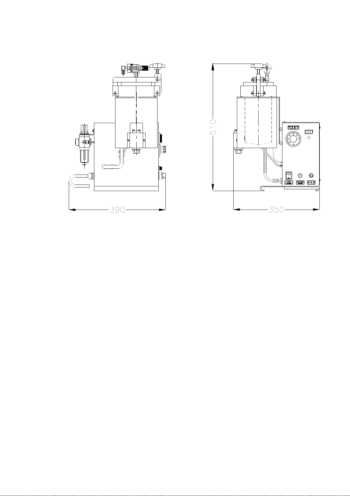
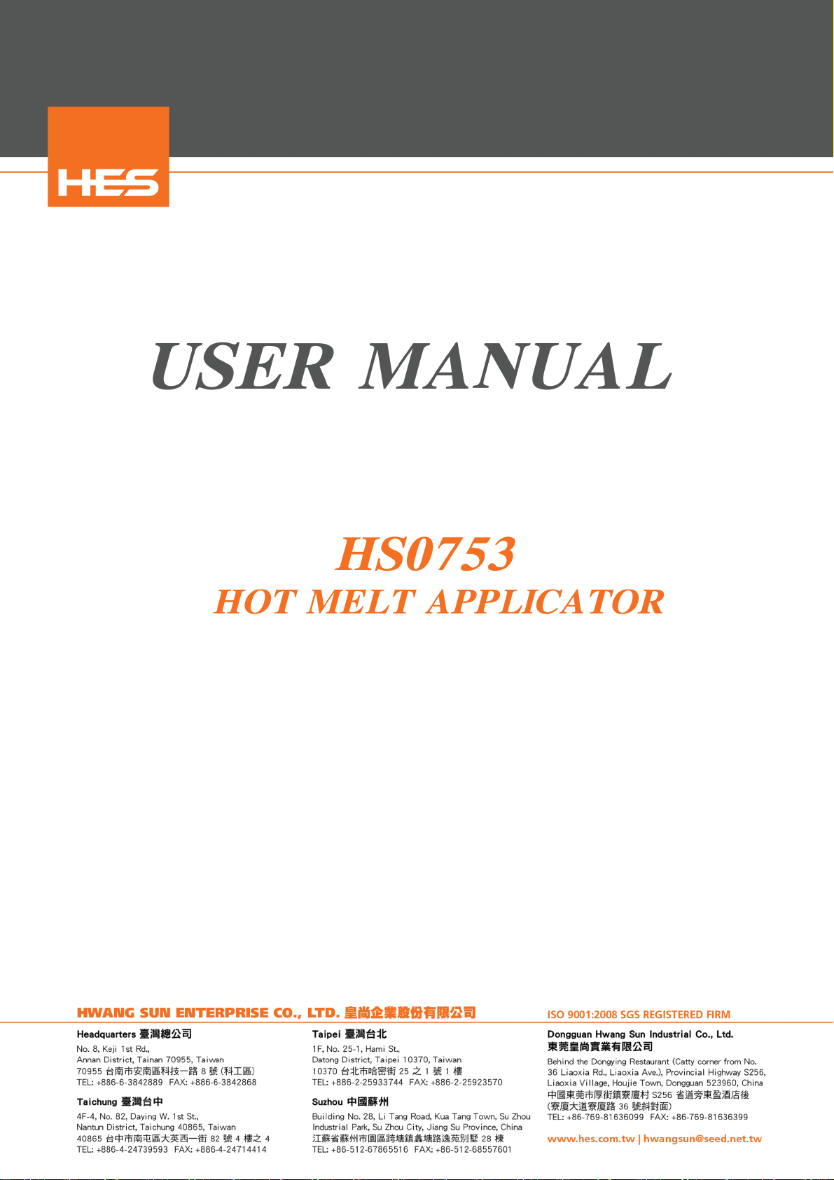
Figure 2.2 Equipment Dimension
2.1 Description Of The Machine Character
The HS0753 Hot Melt Applicator is designed to melt any type or
shape of adhesive with viscosity ranging from 500 to 20000
cps suitable for manual operation.
This equipment has two main system, electrical control system
and heating system including hydraulic system and pneumatic
system.
The solid form hot melt material is melted in a special trat-
ing tank, flow to bottom of the tank and transferred by com-
press air, through the nozzle device for application.
The features of this HS0753 Hot Melt Applicator are:
1. Light weight, small volume, easy to move.
2. Open cap easily, fill materials conveniently and safety.
HS0753-2-02 930906
3. Pneumatic power system.
4. Simple construction, easy to maintain.
5. Pressure and flow are adjustable.
6. Glue melt fast.
7. Glue flow volume can be exactly controlled by electrical
timer.
8. Pressure-keeping system with accurate construction of need-
le valve nozzle reacts quite sensitively.
9. Not suitable for automatically machine system.
Equipment Dimension (High Type)
HS0753-2-03 930906

Figure 2.3 Hydraulic System Diagram
HS0753-2-04 930906

2.2 Specification Summary
Item 0753
Electrical Power 110/220V 50/60Hz
Weight 14.8Kg
Dimension 350X390X510 mm
Melting Capacity 2.5Kg/hr
Tank Capacity 1 Liter
Operation Temp. Max 250 ℃
Air Pressure 2~6 Kg/cm
2
Nozzle Quantity 1 Set
Nozzle Model Pneumatic needle
Wattage 800W
Viscosity Max 20000 CPS
* The melting capacity rate will altered by the type of hot
material.
2.3 Functional Description Of Standard
2.3.1 Power System
The power system of the HS0753 Hot Melt Applicator is pneuma-
tic compress air system. (Refer figure 2.3) The compress air
into the tank, to pressed molten material and outlet from no-
zzle. The quantity of outlet can be control by mane switch or
quantity timer.
2.3.2 Hydraulic System
1. Hot melt tank
The applicator melts adhesives in a Teflon-coated aluminum
tank, in order to avoid the hot melt adhesive adhere on the
wall, become a carbon and difficult to clean the tank. This
tank also able to change hot melt adhesive easily and completely
. In the bottom of the tank sets out a four fins to increase
the heat dissipating rate.
HS0753-2-05 930906

Temperature control is accomplished by means of a resistance
temperature detector (RTD) mounted in the tank wall.
2.3.3 Electrical Power System
1. Heating system
The tank of the HS0753 is electrical heating system. The heat-
er is cover surface of the tank, use a (RTD) temperature sen-
sor to detect the temperature, then transfer the single to the
temperature controller.
2. Temperature controller --- mechanical type controller
Temperature sensor bar contained liquid fully, the volume of
liquid will increase when heated, the additional volume will
force the spring plate of temperature controller through a
pressure tube, the spring plate is opened. When temperature is
rising then switch off the heater and stop heating. When tem-
perature drop down and the spring plate will contact again,
the heater will be switched on and start heating.
CUATION:
The temperature sensor bar of mechanical type temperature con-
trolled must following the condition as below, in order to ma-
intense the properly performance of the sensor.
1. Do not bend or damage the surface of the bar.
2. Do not fold or twist the wire of the sensor.
HS0753-2-06 930906

CHAPTER 3 OPERATION INSTRUCTIONS
3.0 Introduction
In this introduction, it contains the preparing the HS0753
Hot Melt Applicator for operation, loading it with adhesive,
changing the adhesive used in it, and operating it on a daily
basis.
3.1 Safety Precaution
1. Always wear safety glasses, safety gloves, and protective
clothing to prevent injury from hot applicator parts, spla-
shed hot melt adhesive material, and hot nozzle surface.
2. Do not touch the surface of the nozzle tip during operating
this equipment, this is hot.
HS0753-3-01 930906

3.2 The Function Of Control Panel
HS0753-3-02 930906

1. Mechanical temperature
controlled
This temperature controller used
to control the tank temperature.
Setting the temperature by turn
the knob until the red spot re-
ches to required temperature.
2. Indicator Lamp Of Heating
This lamp is located on the ri-
ght side of the temperature con-
troller. When the lamp is on, it
shows that the heating system is
on.
3. The Hot Melt Adhesive Out Let
Timer
This timer is used for "AUTO"
mode hot melt outlet time sett-
ing. Turn the knob, untill the
needle reaches the reguire val-
ue to complate the time setting.
4. MANU/AUTO Switch
This MANU/AUTO switch is used to
select whither the equipment is
on "MANU" mode or "AUTO" mode.
Put this switch on "MANU" posi-
tion, then the then the hot melt
adhesive uotlet is controled by
foot switch. Put the switch on
"AUTO" position, then the hot
melt adhesive outlet is control-
ed by outlet timer.
HS0753-3-03 930906

5. "MAIN POWER" switch
This main power switch is to
control the main power of the
applicator.
Put the switch on "ON" position
and the light of this switch
will on, to shows that system is
on.
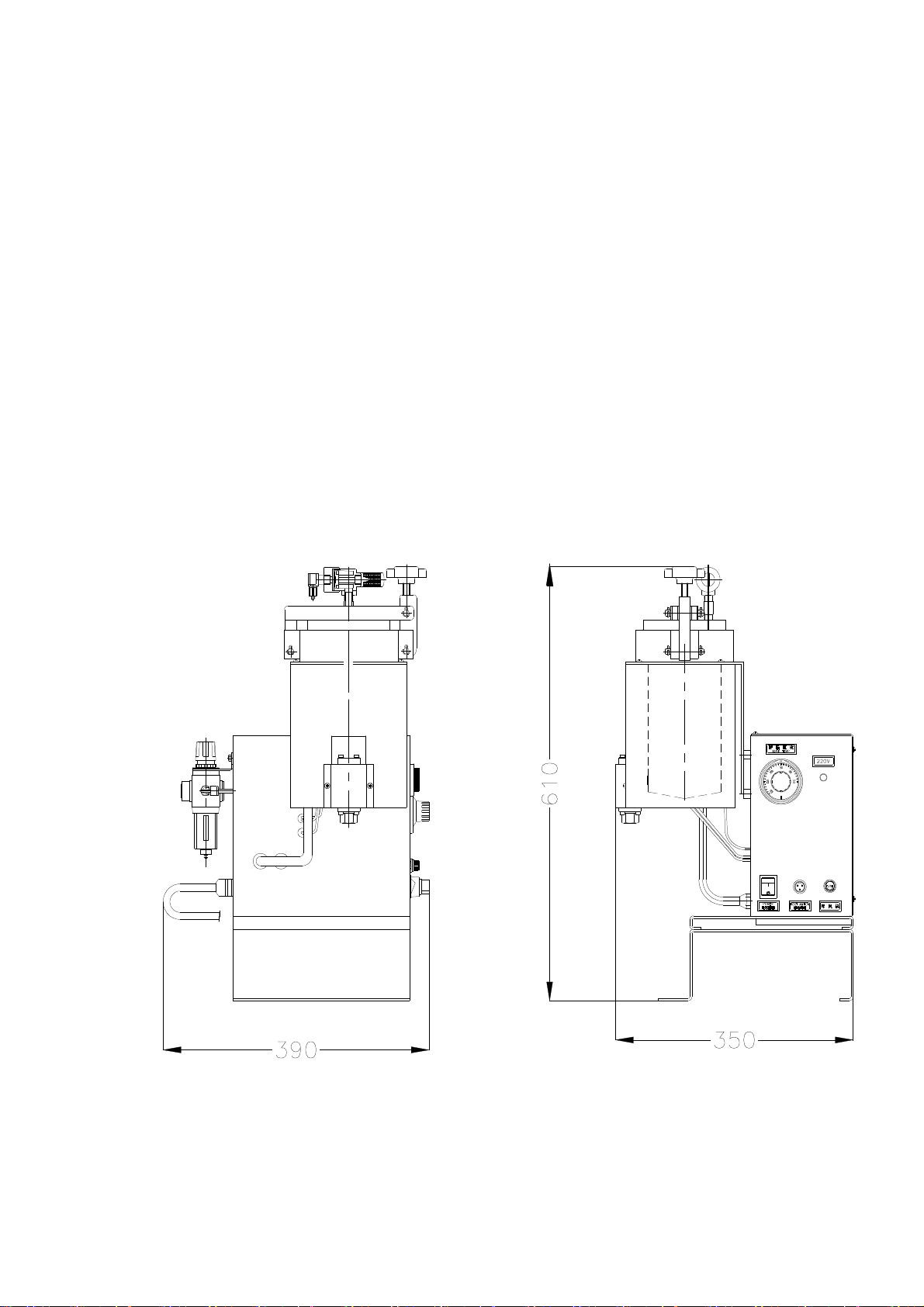
6. Pressure-Keeping Switch
Put this switch on "CHARGE" po-
sition to supply the compress
air for the tank. Before cutoff
the main power, ensure to put
this switch to "DISCHAGE" posi-
tion to relase the pressure from
the quick exhaust valve.
7. Fuse Base
In this fuse base with in a 10A
fuse in order to avoid the over-
load or current shirt, to cause
the damage of the equipment.
8. Foot Switch Plug
This foot switch plug is for ex-
nal foot switch to send a outlet
single.
HS0753-3-04 930906

3.3 Daily Operation
3.3.1 Turn On Precedure
1. Turn on the main power switch.
2. Check the temperature
setting.
3. Check the compress air set-
ting.
4. Check the tank level and add
adhesive material as neces-
sary.
CAUTION:
Do not load over 4/5 of the
ank capacity.
5. Select the operation form
whether "MANU" or "AUTO"
mode.
HS0753-03-05 930906
6. Ensure the tank lid is tight.
7. Put the Pressure - Keeping
switch on the "CHARGE" posi-
tion.
8. In the manu mode, stepping
the foot-switch then the hot
melt adhesive will keeping
outlet, until the foot-
switch is being released.
In the auto mode stepping
the foot switch and release
it then the timer will start
timing, when the time is up
to stop the outlet.
CAUTION:
Reload the adhesive material during the operation, must
discharge the pressure-keeping switch, for open lid easily
and safety.
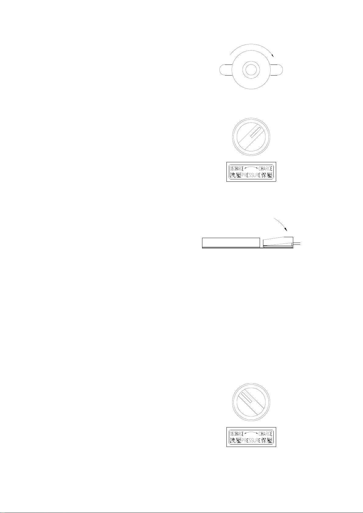
3.3.2 Shut-Off Procedure
1. Put the "Pressure-Keeping"
switch on discharge position.
HS0753-3-06 930906

2. Turn off the main power
switch.
HS0753-3-07 930906
Table of contents
Other HES Industrial Equipment manuals


