HESCH HE 5422 MR User manual

HE 5422 MR
Differential pressure regulator with measuring hose cleaning
Operating manual
Translation of the operating manual
(Original version German)

2Operating manual HE 5422 MR
Version 1.2 • Item number #342232 • 25.03.2019
Imprint
HESCH Industrie-Elektronik GmbH
Boschstraße 8
D-31535 Neustadt
Germany
Phone +49 (0) 5032 9535-0
Fax +49 (0) 5032 9535-99
Internet: www.hesch.de
E-Mail: info@hesch.de
District court Hanover
HRB 111184
Tax-No.: 34/200/22524
VAT No.: DE813919106
Management:
Walter Schröder, Werner Brandis
Publisher:
HESCH Industrie Elektronik GmbH, Documentation Department
Copyrights
© Copyright 2014 HESCH Industrie-Elektronik GmbH. All rights reserved. The content
including pictures and the design of this manual are subject to copyright protection and
other laws for protection of intellectual property. The dissemination or alteration of the
content of this manual is prohibited. Moreover, these contents may not be copied, dis-
seminated, altered or made accessible to third parties for commercial reasons.

Operating manual HE 5422 MR 3
Version 1.2
Table of contents
1 Foreword. . . . . . . . . . . . . . . . . . . . . . . . . . . . . . . . . . . . . . . . . . . . . . . . . . . . . . . . . .4
1.1 Information regarding the usage of these operating instructions. . . . . . . . . . . . . . . . . . . . . . . . 4
1.2 Legal provisions. . . . . . . . . . . . . . . . . . . . . . . . . . . . . . . . . . . . . . . . . . . . . . . . . . . . . . . . . . . . . 6
2 Safety information . . . . . . . . . . . . . . . . . . . . . . . . . . . . . . . . . . . . . . . . . . . . . . . . . .7
2.1 Symbols and basic safety information . . . . . . . . . . . . . . . . . . . . . . . . . . . . . . . . . . . . . . . . . . . . 7
2.2 Safety during the individual phases of operation . . . . . . . . . . . . . . . . . . . . . . . . . . . . . . . . . . . . 9
3 Device description . . . . . . . . . . . . . . . . . . . . . . . . . . . . . . . . . . . . . . . . . . . . . . . . .11
3.1 Overview . . . . . . . . . . . . . . . . . . . . . . . . . . . . . . . . . . . . . . . . . . . . . . . . . . . . . . . . . . . . . . . . . 11
3.2 Display and control elements. . . . . . . . . . . . . . . . . . . . . . . . . . . . . . . . . . . . . . . . . . . . . . . . . . 12
3.3 Differential pressure column . . . . . . . . . . . . . . . . . . . . . . . . . . . . . . . . . . . . . . . . . . . . . . . . . . 13
3.4 Technical data . . . . . . . . . . . . . . . . . . . . . . . . . . . . . . . . . . . . . . . . . . . . . . . . . . . . . . . . . . . . . 14
4 Installation . . . . . . . . . . . . . . . . . . . . . . . . . . . . . . . . . . . . . . . . . . . . . . . . . . . . . . .16
5 Electrical commissioning . . . . . . . . . . . . . . . . . . . . . . . . . . . . . . . . . . . . . . . . . . .17
5.1 Safety notes. . . . . . . . . . . . . . . . . . . . . . . . . . . . . . . . . . . . . . . . . . . . . . . . . . . . . . . . . . . . . . . 17
5.2 Supply voltage . . . . . . . . . . . . . . . . . . . . . . . . . . . . . . . . . . . . . . . . . . . . . . . . . . . . . . . . . . . . . 18
5.3 Connection diagram. . . . . . . . . . . . . . . . . . . . . . . . . . . . . . . . . . . . . . . . . . . . . . . . . . . . . . . . . 19
5.4 Inputs . . . . . . . . . . . . . . . . . . . . . . . . . . . . . . . . . . . . . . . . . . . . . . . . . . . . . . . . . . . . . . . . . . . . 19
5.5 Outputs . . . . . . . . . . . . . . . . . . . . . . . . . . . . . . . . . . . . . . . . . . . . . . . . . . . . . . . . . . . . . . . . . . 19
6 Parametrization . . . . . . . . . . . . . . . . . . . . . . . . . . . . . . . . . . . . . . . . . . . . . . . . . . .20
6.1 Parametrization using device keyboard. . . . . . . . . . . . . . . . . . . . . . . . . . . . . . . . . . . . . . . . . . 20
6.2 Offset for zeroing . . . . . . . . . . . . . . . . . . . . . . . . . . . . . . . . . . . . . . . . . . . . . . . . . . . . . . . . . . . 23
6.3 Parametrization using the Service-PC. . . . . . . . . . . . . . . . . . . . . . . . . . . . . . . . . . . . . . . . . . . 23
6.4 Parameter protection . . . . . . . . . . . . . . . . . . . . . . . . . . . . . . . . . . . . . . . . . . . . . . . . . . . . . . . . 23
6.5 Reset of factory settings . . . . . . . . . . . . . . . . . . . . . . . . . . . . . . . . . . . . . . . . . . . . . . . . . . . . . 24
7 Operation . . . . . . . . . . . . . . . . . . . . . . . . . . . . . . . . . . . . . . . . . . . . . . . . . . . . . . . .25
7.1 Normal operation . . . . . . . . . . . . . . . . . . . . . . . . . . . . . . . . . . . . . . . . . . . . . . . . . . . . . . . . . . . 25
7.2 Testing function . . . . . . . . . . . . . . . . . . . . . . . . . . . . . . . . . . . . . . . . . . . . . . . . . . . . . . . . . . . . 27
7.3 Differential pressure measurement . . . . . . . . . . . . . . . . . . . . . . . . . . . . . . . . . . . . . . . . . . . . . 27
7.4 Measuring hose cleaning. . . . . . . . . . . . . . . . . . . . . . . . . . . . . . . . . . . . . . . . . . . . . . . . . . . . . 29
8 Error messages . . . . . . . . . . . . . . . . . . . . . . . . . . . . . . . . . . . . . . . . . . . . . . . . . . .30
9 Declaration of conformity . . . . . . . . . . . . . . . . . . . . . . . . . . . . . . . . . . . . . . . . . . .31
10 Maintenance and service . . . . . . . . . . . . . . . . . . . . . . . . . . . . . . . . . . . . . . . . . . .32
10.1 Notes . . . . . . . . . . . . . . . . . . . . . . . . . . . . . . . . . . . . . . . . . . . . . . . . . . . . . . . . . . . . . . . . . . . . 32

Chapter 1 Foreword
4Operating manual HE 5422 MR
Version 1.2
1 Foreword
1.1 Information regarding the usage of these operating instruc-
tions
Structure
Target group
These operating instructions are intended for qualified electricians that will install, wire, commission
and parametrize the HE 5422 MR Differential Pressure Regulator.
Chapter 1 Foreword
Information on chapter structure, document history, intended use and device
safety.
Chapter 2 Safety information
Important safety information regarding the Differential Pressure Regulator.
Chapter 3 Device description
Description of the Differential Pressure Regulator, control elements and techni-
cal specifications.
Chapter 4 Installation
Dimensions of the device and scope of delivery.
Chapter 5 Electrical commissioning
Connection of supply voltage and signals.
Chapter 6 Parametrization
Parametrization on the device or with a service PC.
Chapter 7 Operation
Information regarding operation, differential pressure measurements, measur-
ing hose cleaning and error messages.
Chapter 8 Error messages
Information regarding error messages that are shown on the display and indi-
cated by the flashing LEDs.
Chapter 9 Declaration of conformity
Chapter 10 Maintenance and service
Information regarding control operations and disposal

Chapter 1 Foreword
Operating manual HE 5422 MR 5
Version 1.2
Document history
Date / Version Description
10/2013 / 1.0 First creation
04/2014 / 1.1 Chapter 3.1, 3.4, 5.2, 5.3: Changed value for wide-range power supply
(100 – 240 VAV). Chapter 2.2: Changed value for surface temperature. Chap-
ter 6.1: Supplemented factory setting of Δp-Measuring-range (mbar). Chapter
9: Added declaration of conformity. Chapter 8: Added error message (E 4).
03/2019 / 1.2 Chapter 3.4 Technical data:
Operating temperature in EX zone added.

Chapter 1 Foreword
6Operating manual HE 5422 MR
Version 1.2
1.2 Legal provisions
Manufacturer
HESCH Industrie-Elektronik GmbH, Boschstraße 8, D-31535 Neustadt, Germany
Intended use
The HE 5422 MR Differential Pressure Regulator serves the purpose of measuring the dif-
ferential pressure using filter elements as part of the industrial fabric filter technologies and
to operate a valve control unit. The differential pressure is monitored by two alarm thresh-
olds.
The control unit can be operated within the usage and ambient conditions stated in this
manual without causing any safety risks.
The manufacturer is not liable for improper usage and the resulting personnel injuries or
damage; the risk lies entirely with the operator. Failure to comply with the above mentioned
criteria regarding intended use may void the warranty – the manufacturer cannot be held li-
able for damage to the device in this case.
Personnel qualification
Only qualified electricians with the appropriate knowledge in the field of electrical engineering are
allowed to conduct any work on the Differential Pressure Regulator.
Device safety
The device was built and tested in accordance with VDE 0411 / EN 61010-1 and has left the fac-
tory in an operationally safe condition. In order to maintain this condition and to ensure safe opera-
tion, the user has to follow the instructions and warnings contained in this manual, see chapter 2
"Safety information" on page 7.

Chapter 2 Safety information
Operating manual HE 5422 MR 7
Version 1.2
2 Safety information
2.1 Symbols and basic safety information
This chapter contains important safety provisions and information. In order to protect against per-
sonnel injury and damage, it is necessary to carefully read this chapter before working with the de-
vice.
Used symbols
The following symbols are used in this manual. All safety information notes are structured in a uni-
form manner.
Warning of personnel injury!
The severity of the danger is indicated by the respective signal word, see page 8.
Warning of explosive atmosphere!
Warning of dangerous electrical voltage!
Warning of material damage due to electrostatic charging!
Warning of material damage!
Note!
Indicates possible malfunctions and provides information regarding optimal oper-
ating conditions.

Chapter 2 Safety information
8Operating manual HE 5422 MR
Version 1.2
Signal words
DANGER!
Indicates an immediate danger with high risk that will result in death or serious injury if not avoided.
WARNING!
Indicates a possible danger with medium risk that may result in death or serious injury if not
avoided.
CAUTION!
Indicates a danger with low risk that might result in slight or moderate injury if not avoided.
Structure of warning notes
All warning notes in these operating instructions are structured in a uniform manner. The pictogram
designates the type of danger.
SIGNAL WORD!
An informative text describes the danger and suggests how it can be avoided.

Chapter 2 Safety information
Operating manual HE 5422 MR 9
Version 1.2
2.2 Safety during the individual phases of operation
The following safety notes must be observed when installing the device and during operation.
Danger of electric shock!
Disconnect the power supply before working on the device. Install the electrical
lines in accordance with the respectively applicable local regulations (VDE 0100
in Germany). Lay the measuring lines separately from the power lines. Produce a
connection between the protective ground connection (in the respective device
carrier) and a protective ground.
Danger of electric shock!
Any interruption of the protective ground in the device carrier may cause the de-
vice to become dangerous. Deliberate interruptions are not permissible. If it can
be assumed that safe operation is no longer possible, then the device shall be
put out of commission and be secured against unintended operation or re-activa-
tion.
Danger of electric shock!
Do not open the device under voltage! When opening the devices or removing
covers and parts, live parts may become exposed. Connecting points may also
be live!
Caution!
The device may not be put into operation when there is visible damage on the
device.
Caution!
Observe the accident prevention regulations applicable to the system, such as
BGV A 3 "Electrical Systems and Equipment" during installation, commissioning,
maintenance and troubleshooting.
Caution!
Clean soiled contacts using oil-free compressed air or spirit and a lint-free cloth.
Material damage due to electrostatic charging!
Observe the safety measures according to DIN EN 61340-51/-3 in order to pre-
vent electrostatic discharging!

Chapter 2 Safety information
10 Operating manual HE 5422 MR
Version 1.2
The following provisions must be observed:
Attach the cables to the cable glands correctly.
Provide unneeded housing bores with locking bolts.
It is only permitted to clean the housing with wet cleaning agents in order to avoid static
charging.
It is required to clean the device in order to prevent increased dust formation.
Electrical connection!
Install the electrical lines in accordance with the respectively applicable local reg-
ulations (VDE 0100 in Germany). Lay the measuring lines separately from the
power lines. Produce a connection between the protective ground connection (in
the respective device carrier) and a protective ground.
Explosion protection!
The device is suitable for operation in explosion zone 22 with the lid closed. Prior
to opening the device, it has to be ensured that there are no explosive ambient
conditions, such as dust development.
The device is marked with:
II Not suitable for mines susceptible to firedamp
3D Dusts, normal safety
T135°C Surface temperature
IP65 Protection class: dust-proof, scoop-proof
Troubleshooting!
When beginning to troubleshoot, all possible sources of error regarding additional
equipment or cables (measuring cables, wiring, slave devices) should be taken
into consideration. If no error source can be found after examining these points,
we recommend to send the device to the supplier.
Decommissioning!
Disconnect the power supply entirely if the device is to be decommissioned. Se-
cure the device against inadvertent operation!
If the device is interconnected with other devices and/or equipment, the effects of
the deactivation should be considered prior to disconnecting the device and the
appropriate precautions should be taken beforehand.

Chapter 3 Device description
Operating manual HE 5422 MR 11
Version 1.2
3 Device description
3.1 Overview
Fig. 3.1: Overview
A. Type designation
B. Display and control elements
C. Cable glands
A
B
C
Chapter 3 Device description
12 Operating manual HE 5422 MR
Version 1.2
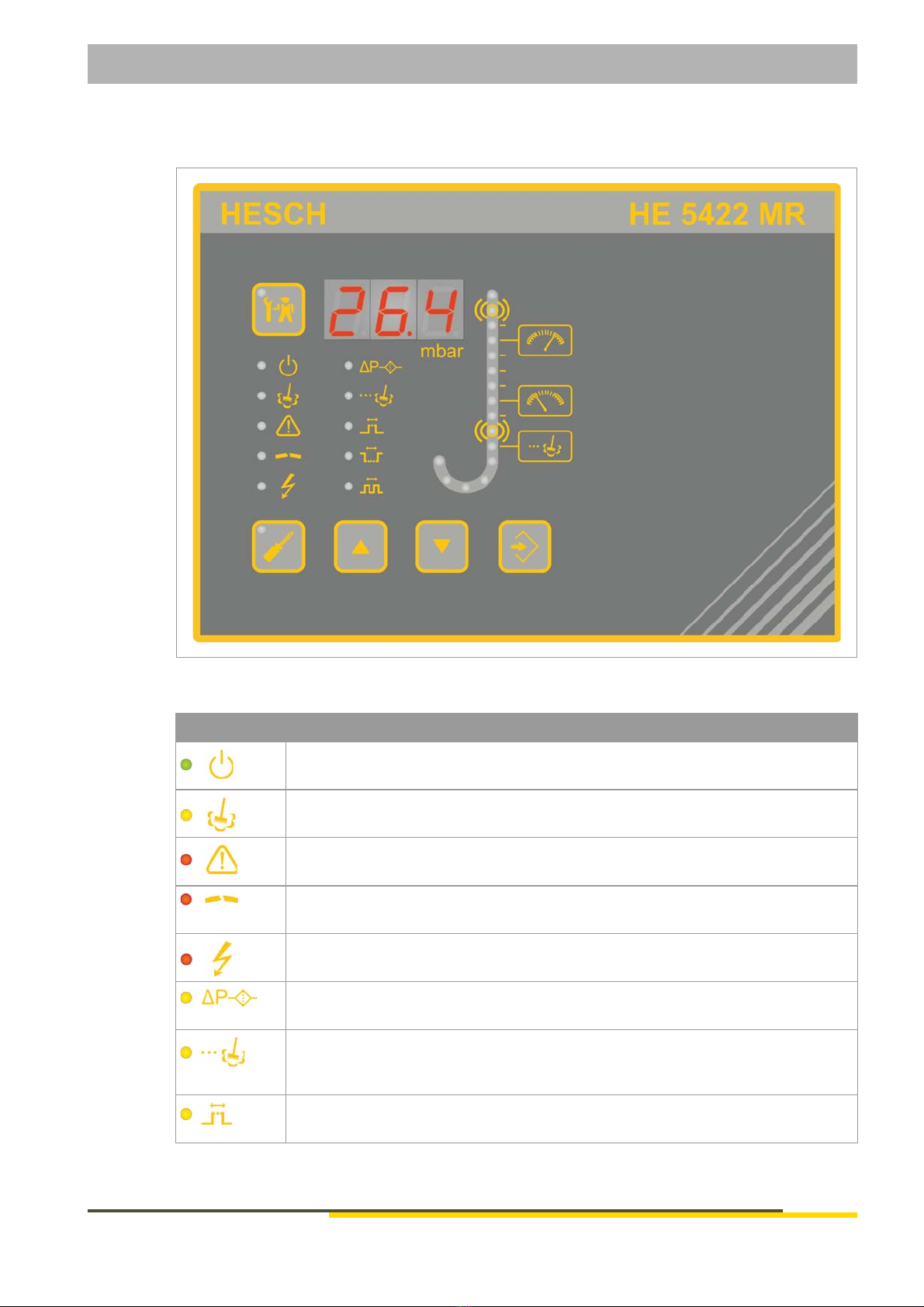
3.2 Display and control elements
Fig. 3.2: Display and control elements
Symbols Meaning
Operation message
Cleaning active
Alarms active
Interruption on one valve
Short-circuit of a valve (over current)
Filter constant of the differential pressure measurement
Post cleaning time
Normal operation: LED lights up when post cleaning is active
Parametrization mode: LED flashes when the parameter can be selected
Blowing time: opening time of the blow air valve

Chapter 3 Device description
Operating manual HE 5422 MR 13
Version 1.2
3.3 Differential pressure column
Fig. 3.3: Differential pressure column
In normal operating mode, the LEDs serve the purpose of displaying the differential pressure.
In parametrization mode, the selected parameter value is indicated by flashing.
Recovery time: delay to restore the pressure balance after the blowing time
Interval: waiting time until the next measuring line cleaning cycle
TEST button: testing mode ON/OFF
PARA button: parametrization mode ON/OFF
UP button: increase displayed value
DOWN button: reduce displayed value
ENTER button: accept/confirm displayed value
Display:
Normal operation: current differential pressure
Parametrization mode: parameter values
Alarm indications
Symbols Meaning
ΔP measuring range
High alarm
Upper threshold – Cleaning start
Lower threshold – Cleaning stop
Low alarm
Post cleaning threshold
Zeroing

Chapter 3 Device description
14 Operating manual HE 5422 MR
Version 1.2
3.4 Technical data
Technical data
Measuring range: Maximum of 35 mbar (90 or 450 mbar on request)
Maximum differential
pressure:
160 mbar
Basic accuracy: ± 1% of final value
Temperature drift: ± 0.05% / K of final value
Hysteresis: ± 0.5% of final value
Intended use: Differential Pressure Regulator with integrated Measuring Hose Clean-
ing used to control the cleaning of industrial filtration plants
Supply voltage: 100 – 240 VAC ±10%
24 VDC ±10%
Power consumption: Max. 30 W
Display: 7-segment display, 3 digits, 14 mm high, red for differential pressure dis-
play, parameter values and alarm messages
LEDs: 7 LEDs for status indications
16 LEDs for differential pressure indications
Buttons: PARA (ESC), UP, DOWN, ENTER, TEST
Analogue output: 4...20 mA
Galvanically isolated
Max. permissible load: 400 Ω
Digital inputs: Start, post cleaning. Internally supplied by 24 VDC / 1 mA
Relay outputs: 1 change-over contact 250 VAC, 5 A as a combined operating and
fault indicator
1 NO contact 250 VAC, 5 A as a cleaning indicator
2 change-over contacts 250 VAC, 5 A as alarm indicators
Interfaces: USB Device, Type B for reading and writing of parameters (USB / TTL
adapter required)
Creepage distances
and clearances:
Contamination Class 2
Over voltage Category II
EMV: Interference emission: DIN EN 61000-6-4
Interference immunity: DIN EN 61000-6-2
Housing: ABS (acrylonitrile-butadiene-styrene)
IP65 Protection Class
Dimensions: 200 mm × 150 mm × 100 mm (W × H × D)
Cable glands: 1 x M25 with multiple sealing insert for 4 liens with 6 mm diameter
1 x M20 for supply and communication
Electrical connections: Power supply: rigid/flex cross-section 2.5 mm2; flex.: max. 1.5 mm2
with wire end ferrule
Rest: rigid/flex cross-section 1.5 mm2; flex.: max. 0.75 mm2 with
wire end ferrule

Chapter 3 Device description
Operating manual HE 5422 MR 15
Version 1.2
Subject to technical changes.
Pneumatic connections: Pressure measuring line: 2 × push-in bulkhead connector for Ø6 mm
hose
Blowing pressure connection: 1 × push-in bulkhead connector for
Ø8 mm hose
Maximum blowing pressure: 8 bar
Installation: Wall mounting, mounting position: vertical
Ambient conditions
Climatic
Storage -20°C … +70°C
Transport -40°C … +85°C
Operation -20°C … +50°C
in EX zone: -20 °C ... +40 °C
Relative humidity Relative humidity 95%, no condensation allowed, KUF in accordance
with DIN 40400
Technical data

Chapter 4 Installation
16 Operating manual HE 5422 MR
Version 1.2
4Installation
The ambient temperature at the installation position may not exceed the permissible temperature
for rated use listed in the data sheet. The device may be installed in areas subject to the EX ATEX
Zone 22 Explosion Class. The special provisions should be observed, see chapter 2.2 "Safety dur-
ing the individual phases of operation" on page 9.
Dimensions
Fig. 4.1: Dimensions
Scope of delivery
HE 5422 MR
Operating Manual
Note!
After receiving the delivery, check it for completeness and obvious defects. In
case of a complaint, immediately contact your local HESCH representative.

Chapter 5 Electrical commissioning
Operating manual HE 5422 MR 17
Version 1.2
5 Electrical commissioning
Mind the following points prior to turning on the device:
Firmly connect the cables to the glands. The supply voltage must match the specifications
on the type plate.
The device may only be operated in a closed state.
The temperature limitations specified for use of the device have to be observed before and
during operation.
The protective ground connection in the appropriate device carrier has to be conductively
connected to the protective ground
5.1 Safety notes
Danger of electric shock!
Only perform the electrical installation in a dead-voltage state.
Material damage due to electrostatic charging!
Observe the safety measures according to DIN EN 61340-51/-3 in order to pre-
vent electrostatic discharging!
Note!
Only qualified specialists may work on the electronics.

Chapter 5 Electrical commissioning
18 Operating manual HE 5422 MR
Version 1.2
5.2 Supply voltage
Fig. 5.1: Supply voltage
1. Loosen the screws on the housing cover (lid) and remove the cover.
2. Read the supply voltage value off the type plate (for example 100 – 240 VAC and 24 VDC
mains voltage).
3. Connect PE conductors.
Note!
Both supply voltages may be connected at the same time.
100 – 240 VAC
24 VDC
+24 VDC
GND
PE
L1
N
PE

Chapter 5 Electrical commissioning
Operating manual HE 5422 MR 19
Version 1.2
5.3 Connection diagram
Fig. 5.2: Connection Diagram
5.4 Inputs
The ΔP controller has 2 inputs: Start and Post cleaning. The inputs are internally supplied with +
24 V DC and are active when they are switched to ground (GND) with a potential-free contact.
5.5 Outputs
Relay
The device is equipped with 4 potential-free relay outputs.
The contacts can each be loaded with 250 VAC / 5 A.
Analogue output
The current differential pressure is reported by a galvanically isolated 4…20 mA signal.
Note!
The inputs refer to the same ground (-). It is permissible to use one ground wire
for both inputs.

Chapter 6 Parametrization
20 Operating manual HE 5422 MR
Version 1.2
6 Parametrization
6.1 Parametrization using device keyboard
1. Press the PARA button to change the system parameters.
A flashing LED indicates the current value to be changed.
2. Select the desired parameter using the UP / DOWN buttons.
The respectively current value is indicated on the display.
3. Press the ENTER button to start changing the value of the parameter.
The first digit to be changed starts flashing in the display.
4. Press the UP / DOWN buttons to select or change the value of the digit.
5. Press the ENTER button to accept the current value.
The next digit will subsequently flash in the display.
6. Repeat steps 4 – 5 until the last digit has been changed.
The next parameter is offered.
7. If necessary, change the next parameter.
8. The parametrization mode is exited by pressing the PARA button again.
Main parameter Setting area Factory setting
ΔP-Filter [s]
Filter constant for the current dif-
ferential pressure
OFF, 0.2 – 60.0 s 2
Post cleaning time [min]
The cleaning relay is closed for
the parametrized time for post
cleaning purposes.
OFF, 1 – 999 min 10 min
Blowing time [s]
During the blowing time, the com-
pressed air is blown into the
measuring lines.
1 – 999 s 10 s
Recovery time [s]
Delay used to restore the pres-
sure balance after the blowing
time.
1 – 999 s 50 s
Interval [min]
Waiting time until the next meas-
uring line cleaning cycle.
0 – 999 min 60 min
Table of contents
Other HESCH Controllers manuals


