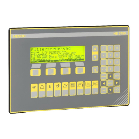
HESCH HE 5750 User manual

Solenoid Valve Control
HE 5750
Operating instructions
(Original Language German)
# 371521| Version 2.15

2
HESCH Industrie-Elektronik GmbH
HE 5750, Version 2.15, 22.01.2020 # 371521
Disclaimer
HESCH Industrie-Elektronik GmbH
Boschstraße 8
D-31535 Neustadt
Germany
Phone +49 5032 9535–0
Fax +49 5032 9535–99
Website: www.hesch.de
District Court Hanover
HRB 111184
VAT no.: DE813919106
Executive Board:
Walter Schroeder, Werner Brandis
Publisher:
HESCH Industrie Elektronik GmbH, Documentation Department
Copyrights
© Copyright 2020 HESCH Industrie-Elektronik GmbH. All rights reserved.
The content of this operating manual incl. images and design are subject
to the protect of copyright and other laws regarding the protection of intel-
lectual property. The distribution or modification of this manual is not per-
mitted and its content may not be copied, distributed, modified or made
availabe to third parties for commercial use.

HESCH Industrie-Elektronik GmbH
3
HE 5750, Version 2.15, 22.01.2020 # 371521
Table of Content
2. Legal Regulations...................................................................................................................... 6
3. Safety Guidelines....................................................................................................................... 7
3.1. Symbols and basic safety guidelines........................................................................................... 7
3.2. Safety during the individual operating phases............................................................................. 8
4. Glossary ................................................................................................................................... 11
4.1. Filtersystem Skizze.................................................................................................................... 11
5. Device Description .................................................................................................................. 13
5.1. Display....................................................................................................................................... 13
5.2. General Description................................................................................................................... 13
5.3. Communication Structure.......................................................................................................... 14
5.4. System Setup ............................................................................................................................ 14
5.5. System Layout........................................................................................................................... 15
5.6. Components .............................................................................................................................. 16
6. Installation and Housing......................................................................................................... 18
6.1. Network supply.......................................................................................................................... 18
6.2. Device Dimensions.................................................................................................................... 18
7. Commissioning........................................................................................................................ 19
7.1. In- and Outputs (rear display HE 5750)..................................................................................... 19
7.2. Standard Assignment ................................................................................................................ 19
7.3. Galvanic Isolation ...................................................................................................................... 19
7.4. Setting of the common baud rate in the CAN network .............................................................. 20
7.5. Setting of the node no. (address) .............................................................................................. 21
7.6. Local control at control cabinet.................................................................................................. 22
7.7. Limitation of local operation....................................................................................................... 22
7.8. Network Topology diagramm.................................................................................................... 23
7.9. System start............................................................................................................................... 25
8. Display and operating keys.................................................................................................... 26
8.1. Numeric keypad and input block ............................................................................................... 26
8.2. Function keys F5 –F16............................................................................................................. 27
8.3. Context-sensitive keys F1 –F4 ................................................................................................. 32
8.4. Filter time of circulation.............................................................................................................. 35
9. Parameter ................................................................................................................................. 36
9.1. Open Parameter Menu.............................................................................................................. 36
9.2. Parameter Groups ..................................................................................................................... 36
9.3. Passwords ................................................................................................................................. 36
9.4. Parameter Table (1/3)................................................................................................................ 37
9.5. Parameter Table (2/3)................................................................................................................ 38
9.6. Parameter Table (3/3)................................................................................................................ 39
10. Commands ............................................................................................................................... 64
10.1 Command Sources................................................................................................................ 64
10.2. Command Flowchart............................................................................................................ 65
10.3. Local/Remote Operation...................................................................................................... 66
11. Alarm and Error Messages..................................................................................................... 67
11.1. System Start......................................................................................................................... 67
11.2. Alarm Screens...................................................................................................................... 68
11.3. Alarms of ongoing operation................................................................................................ 69
12. Communication........................................................................................................................ 74

4
HESCH Industrie-Elektronik GmbH
HE 5750, Version 2.15, 22.01.2020 # 371521
12.1. Master –Slave CAN Communication ................................................................................ 74
12.2. Data Direction PLC → HE 5750........................................................................................ 76
12.3. Data direction HE 5750 →PLC ........................................................................................... 77
12.4. Diagnosis HE 5750 at PLC .................................................................................................. 79
13. Solenoid Valve Control ........................................................................................................... 81
13.1. Description ........................................................................................................................... 81
13.2. Supply HE 5724 ................................................................................................................... 81
13.3. State Diagnosis HE 5724..................................................................................................... 81
13.4. Terminals and Jumpers........................................................................................................ 82
13.5. CAN Wiring and Bus Connection......................................................................................... 83
14. Technical Data HE 5750 .......................................................................................................... 84
15. Options ..................................................................................................................................... 86
15.1. Central dust monitoring........................................................................................................ 86
15.2. Reset dust valves................................................................................................................. 88
16. Maintenance and Service........................................................................................................ 89

HESCH Industrie-Elektronik GmbH
5
HE 5750, Version 2.15, 22.01.2020 # 371521
Legal Regulations
1. Document History
Software
version
Date
Description
2.12
11/2014
Layout modifications, general revision.
(Based on 371617, version 2.12)
2.13
08/2016
Softwareversion 2.13 (Cycle time, dust sensor)
Chapter 15.2 (Option: Variable number of valves) deleted
2.13
2017-02-03
Chapter 15: Missing numbering completed.
Correction of the parameter description 7.12, 7.18, 7.3, 7.4
2.13
2018-12-18
Correction in “Explanation of parameter table above” “Pa-
rameter valves” 5.1, 5.2-5.4 summarized to 5.2
2.14
2019-05-21
Subchapter 9.4 Table of parameters (1/3): New parameters
added.
Chapter 12.2 Data Direction PLC → HE 5750, 12.3. HE
5750 → PLC :Function “Parallel valve control inhibit” add-
ed
Notes added in subchapter 1.System parameters and 5.
Parallel valves.
2.15
2020-01-22
Software amendments
Section 9.6: Item 14.9 amended, Item 1.3 text concerning
valve assignment in 2 slave boxes removed.
Section 15.2 amended.

6
HESCH Industrie-Elektronik GmbH
HE 5750, Version 2.15, 22.01.2020 # 371521
Legal Regulations
2. Legal Regulations
HESCH Industrie-Elektronik GmbH, Boschstraße 8, D-31535 Neustadt
The device is exclusively intended for the use as measuring and testing device in
technical systems. The device can be operated within the approved ambient condi-
tions (see "Technical Data" without impairment of its safety. The manufacturer is not
responsible for non-intended use resulting in personnel injury and property damage;
solely the user bears the risk. Non-compliance with the a.m. criteria regarding the
intended use shall result in termination of the warranty and guarantee of the device.
Only trained electricians with sufficient know-how in electrical engineering shall per-
form works at the valve controller.
The device shall only be operated by trained personnel. Only trained and professional
persons who are accustomed to the dangers thereto shall perform maintenance and
repair.
This device is assembled and reviewed acc. To VDE 0411 / EN 61010-1 and left the
plant in flawless technical safety condition. The device was reviewed prior to delivery
and has passed the mandotry tests specified by the test protocol.
To retain this condition and to ensure a safe operation the user must pay attention to
the guidelines and warnings, which are included in such safety guidelines and the
operating manual.
Unpack device and accessories: attached standaard accessories:
Operating instruction resp. Operating guideline and fixing elements, if necessary. The
correctness and completeness of the delivery shal be checked. The device shall be
inspected with regard to damages due to non-intended handling by transport and stor-
age.
Warning!
The device may not be operated if damages that let assume that a safe
operation is not possible.
Manufacturer
Intended Use
Qualified Staff
Device Safety
Unpack Device

HESCH Industrie-Elektronik GmbH
7
HE 5750, Version 2.15, 22.01.2020 # 371521
Safety Guidelines
3. Safety Guidelines
3.1. Symbols and basic safety guidelines
This chapter includes important safety regulations and guidelines. For the protection of
personnel injury and property damage it is necessary to read this chapter carefully
before operating the device.
Following symbols are used in this operating manual. All safety guidelines are struc-
tured coherently.
Warning against personal accidents!
The severance of the risk is characterised by the respective signal word
(.u.).
Warning against explosive atmosphere!
Warning against property damage by electrostatic charge!
Warning against property damage!
Warning against danagerous electric voltage!
Note!
Indicates possibe malfunctions and provides guidelines for optimal oper-
ating conditions.
DANGER!
Indicates a direct danger with high risk that may result in death or severe body injury,
if not prevented.
WARNING
Indicates a possible endangerment with medium risk that may result in death or se-
vere body injury, if not prevented.
ATTENTION
Indicates a possible endangerment with medium risk that may result in death or se-
vere body injury, if not prevented.
Signal words

8
HESCH Industrie-Elektronik GmbH
HE 5750, Version 2.15, 22.01.2020 # 371521
Safety Guidelines
All warning signals in this manual are structured coherently. Thereby the pictogram
indicates the nature of the risk.
SIGNAL WORD! (indicates the severance of the danger)
An indication text desribes the danger and provides references as how
they it can be prevented.
3.2. Safety during the individual operating phases
Attention to the following safety guidelines shall be paid during the installation
of the system and during the operation.
Attention!
Pay attention to the respective accident prevention regulations for your
system, such as e.g. DGUV Regulation 3 "Electric Systems and Operat-
ing Material" during installation, commissioning, maintenance and trou-
bleshooting.
3.2.1 Unpacking device
Warning against personnel injuries and property damages!
The device must be inspected with regard to damages due to improper
handling during transport and storage. The device shall not be operated if
it shows damages that let assume that a safe operation is not possible.
3.2.2 Installation
Warnung vor Personen und Sachschäden!
The installation is carried out in places that comply with the nature of
the protection. The ambient temperature at the installation site shall
not exceed the mentioned permissibe temperature specified for opera-
tion. The devices shall be installed exclusively outside of explosive
areas!
3.2.3. Electric Connection
Danger due to electric shock!
All voltage supplies in use must be switched off prior to the work. Electric
cables must be laid according to the respective country specifications (in
Germany VDE 0100). The measuring leads shall be laid separately from
the network cables. The connection between the protective conductor
connection (in the respective device carrier) and a protective conductor
must be established.
It is recommended to use twisted and shielded measuring leads to avoid
the influence of interference fields. The electrical connection takes place
according to the connection schedules / connection images of the re-
spective device.
Structure of
warning signals

HESCH Industrie-Elektronik GmbH
9
HE 5750, Version 2.15, 22.01.2020 # 371521
Safety Guidelines
3.2.4 Commissioning
Prior to switching on the device it must be ensured that the following points are
considered:
supply voltage complies with the information on the indicating label;
all required covers for contact safety must be fitted.
prior to switching on the device, the impact and respective precautions
must be taken if the device is connected to other devices and / or equip-
ments.
The protective conductor connection in the respective device carrier must be
connected to the protective conductor (in devices with protection class I).
Warning against personnel injuries and property damages!
Any interruption of the protection conductor in the device carrier can lead
to the fact that the device becomes dangerous. Intended interruptions are
not permitted. The device must be disconnected and protected against
unintentional operation if it is assumed that a safe operation is not possi-
ble anymore.
Attention!
The device shall never be commissioned despite visible damages.
3.2.5 Troubleshooting
At the beginning of the troubleshooting all possibilities of error sources at
additional devices resp. supply lines (measuring leads, wiring, sequential devices)
must be considered. We suggest to send the device to the supplier if the error could
not be found after reviewing these points.
Danger due to electric shock!
Do not open the device under voltage! Voltage carrying parts can be
exposed during the opening of the devices or during the removal of co-
vers and parts. Also connecting points can carry voltage!
3.2.6 Decommissioning
Attention!
During decommissioning of the device, the supply voltage must be
completely disconnected. The device must be protected against unin-
tended operation. Prior to disconnecting, the impact and respective
precautions must be considered if the device is connected to other
devices and / or equipments.

10
HESCH Industrie-Elektronik GmbH
HE 5750, Version 2.15, 22.01.2020 # 371521
Safety Guidelines
3.2.7 Maintenance, Repair and Modification
The devices do not require special maintenance.
Modifications, maintenance and repair must be performed by trained
professional experts only.
If the failure of a fuse is detected, the cause must be inspected and removed. The
replacement fuse must have the same data as the original type.
The use of patched fuses or short circuiting the fuse holder are not allowed.
Warning!
Voltage carrying parts can be exposed during the opening of the de-
vices or during the removal of covers and parts. Also connecting
points can carry voltage! The device must be disconnected from all
voltage sources prior to these works..
Property damages by electrostatic charge!
During the opening of the devices may expose components,
which are sensitive against electrostatic discharge (ESD).
The following works shall only be performed at work places that
are protected against ESD!
3.2.8 Explosion protection
Devices without EX protection shall not be operated in potentially explosive areas.
Furthermore out- and inputs of electrical circuits of the device / device carrier shall not
lead into potentially explosive areas, with the exclusive exception of devices for which
a declaration of EX conformity exists. In addition, the information of the related con-
formity declaration and the respective country specifications for the installation of elec-
trical systems in potentially explosive areas must be considered for these EX devices.

HESCH Industrie-Elektronik GmbH
11
HE 5750, Version 2.15, 22.01.2020 # 371521
Glossary
4. Glossary
4.1. Filtersystem Skizze
Glossary
Valve sequence
A valve offset of 2 causes: valve 1, valve 3, valve 5 ... are
triggered
Chamber sequence
A chamber offset of 1 causes:
chamber 1, chamber 2, chamber 3 .... are cleaned. A
chamber offset has higher priority than a valve offset. A
chamber offset of 0 causes:
all valves acc. to valce sequence in chamber 1 are pulsed.
Then chamber 2 etc...
Operating mode
- Permanent
Permanent processing of the parameterised valve se-
quence. Controller via start / stop signals.
- dP Threshold
Control of the cleaning process via the dP signal. Cleaning
starts during exceeding of the parameterised upper thresh-
old; stops when dropping below the lower threshold.
- dP Controller
dP signal and air flow signal Influence the cleaning process.
The breaks are controlled and regulated in dependence
with the filter characteristics to be set via the supporting
points.
Online cleaning
The dampers for pure gas and raw gas stay open during
the cleaning.
Offline cleaning
During the cleaning of a chamber the selected dampers of a
chamber are Off. Within the chamber the valve sequence is
applied. After the cleaning the chamber sequence is con-
sidered.
Semi Compartment
Offline Cleaning
SCOC
‘Half-Chamber Offline Cleaning’. Requires two pure gas
dampers per chamber. By that way one half of the chamber
can be cleaned offline, while the other half remains in the
filter process.
Post cleaning
Post cleaning may be required if the complete filter has
been taken out of the procedure.The post cleaning com-
prises of the complete filter and performs the parameterised
amount of cycles / valves etc. The post cleaning uses ‘cyc-
letime 2’.
Background cleaning
The background cleaning becomes active if no ‘regular’
cleaning is performed for a parameterisable time. This is
often the case in small air flows or low dust inputs.
The differential pressure is reviewed regarding a minimum
value at the same time. If the reading falls short it is as-
sumed that no fan operation exists and the cleaning is
discontinued.

12
HESCH Industrie-Elektronik GmbH
HE 5750, Version 2.15, 22.01.2020 # 371521
Glossary
Partial cycle
Cleaning runs as long as the required start condition is
present. If the start condition is missing, the cleaning will be
interrupted. The cleaning then will be resumed at interrupti-
on point.
Complete cycle
If the required start condition is set, a cleaning cycle via all
active valves is performed.
Forced cleaning
Independently of other necessary conditions (e.g. dP-
thresholds) the setting of this condition starts the cleaning
process. Cleaning runs as long as the condition is set, resp.
in cleaning cycle until all active valves are cleaned.
In connection with the operating mode partial cycle the
valves can be individually processed.
Drain valves
The control supports the drain valves at the local manifold.
Parameters 4.14 to 4.16.

HESCH Industrie-Elektronik GmbH
13
HE 5750, Version 2.15, 22.01.2020 # 371521
Device Description
5. Device Description
5.1. Display
Image 1 HE 5750, display with history
1. Type classification
2. Display and operating elements
5.2. General Description
The system control HE 5750 is the central unit in a CAN based network of the clean-
ing control system for industrial hose filters. The central control communicates with
the decentralised valve control units HE 5724 and the damper control units HE 5740
via the industrial CAN bus.
Coordination and monitoring of all connected components and the communication
with the control technology is performed by the central control.
The Slave controller HE 5724 controls the valve control and reviewing process.
Damper control units form the interface to the damper actuators.
1
2

14
HESCH Industrie-Elektronik GmbH
HE 5750, Version 2.15, 22.01.2020 # 371521
Device Description
5.3. Communication Structure
The central control HE 5750 is the master in the CAN bus system of the filter control-
ler system. A PROFIBUS or a ModBus interface is alternatively available for the con-
trol technology. Altlernatively also a parallel interface for the binary signal exchange is
available. However, the complete signal list can only be reached via the serial inter-
faces.
5.4. System Setup
After correct installation of the unit connections among each other, setting up of the
parameters must take place. For a list of the complete parameters with description
please refer to chapter 5.
The operating parameters can be set up via the keyboard of the central control and
also via ‘Smart Tool’ software. The configuration of the "Extra I/O" is possible via
‘Smart Tool’ only. Parameters from the controller can be loaded, and saved, and the
original project data be restored with the free version of ‘Smart Tool’.
See brief operating manual ‘Brief Manual’ on the documentation CD.

HESCH Industrie-Elektronik GmbH
15
HE 5750, Version 2.15, 22.01.2020 # 371521
Device Description
With the option remote maintenance in ‘SmartTool’, a modem connection to the con-
trol can be established to perform remote maintenance and diagnosis of plants.
5.5. System Layout

16
HESCH Industrie-Elektronik GmbH
HE 5750, Version 2.15, 22.01.2020 # 371521
Device Description
5.6. Components
5.6.1. Master control cabinet
Width = 600 mm
Height = 600 mm
Depth = 350 mm
Weight: 28,5 kg
5.6.2. Damper control cabinet
Width = 500 mm
Height = 500 mm
Depth = 210 mm
Weight: 16,8 kg
Or:
Width = 600 mm
Height = 600 mm
Depth = 210 mm
Weight: 22,8 kg
5.6.3. Valve Control (Slave Box)
Width = 380 mm
Height = 300 mm
Depth = 155 mm
Weight: 7,5 kg
5.6.4. HE 1149 Pressure transmitter, Manifold pressure sensor
Width = 78 mm
Height = 48 mm

HESCH Industrie-Elektronik GmbH
17
HE 5750, Version 2.15, 22.01.2020 # 371521
Device Description
5.6.5. Differential pressure sensor (options)
HE 5421
Width = 120 mm
Height = 122 mm
Depth = 55 mm
HE 5422
Width = 130 mm
Height = 130 mm
Depth = 60 mm
HE 5422 MR
(with measuring
hose cleaning)
Width = 200 mm
Height = 150 mm
Depth = 100 mm

18
HESCH Industrie-Elektronik GmbH
HE 5750, Version 2.15, 22.01.2020 # 371521
Installation and Housing
6. Installation and Housing
The device must be assembled in such a way that it is protected from humidity and
contamination. The permissible ambient temperature (50°C) must not be exceeded.
The electrical connections must be performed according to the relevant VDE, resp. the
local regulations. The connection of the device must always take place in voltage-free
condition.
The existing contactors in the control cabinet must be troubleshooted with RC net-
works. The device includes a network filter. In transient interference voltages an addi-
tional external network filter may be required. This is not included in the standard
scope of delivery, however can be purchased via HESCH Industrie-Elektronik GmbH.
6.1. Network supply
The controller requires 24 VDC. The power consumption is approx. 0.5A
Attention!
Check the correct voltage level prior to switching on the device. In
faulty connection the device suffers serious damage.
6.2. Device Dimensions
Device Dimension Control panel cut-out
295 x 200 x 40 mm (w x h x d) 265 x 170 mm
Rear display HE 5750

HESCH Industrie-Elektronik GmbH
19
HE 5750, Version 2.15, 22.01.2020 # 371521
Commissioning
7. Commissioning
7.1. In- and Outputs (rear display HE 5750)
7.2. Standard Assignment
7.3. Galvanic Isolation
„Digital Output“ and
„Digital Input“ require a
separate supply
DO1:
Operation
IN1:
Local control
DO2:
Cleaning active
IN2:
Acknowledgement
DO3:
Error
IN3:
Local cleaning
DO4:
Pulse signal (1 sec)
IN4:
Filter stop
DO5:
Lamp test
IN5:
Post cleaning
DO6:
Inverted IN8
IN6:
Offline cleaning
DO7:
Central locking valve
IN7:
Synchronization
input for dp clean-
ing
DO8:
dp cleaning signal
IN8:
Reserved (D06)

20
HESCH Industrie-Elektronik GmbH
HE 5750, Version 2.15, 22.01.2020 # 371521
Commissioning
7.4. Setting of the common baud rate in the CAN network
All participants in the CAN network must have the same baud rate. Limits for the max.
baud rate are set by the network extension. In general, the following rule applies: only
as fast as necessary, not as fast as possible. The factory setting is 50 kbd.
Master Setting:
Slave Setting:
Network extension:
Baud rate [kbaud]
Network extension [m]
500
100
250
200
100
600
50
1200
Other manuals for HE 5750
1
Table of contents
Other HESCH Controllers manuals
Popular Controllers manuals by other brands

Eastern Times Technology
Eastern Times Technology BT-100 quick start guide

National Instruments
National Instruments sbRIO-9608 Quick reference guide
Vortice
Vortice C 2.5 Instruction booklet
Omron
Omron SYSMAC CS1W-CLK11 Operation manual

hpmont
hpmont MONT30 Starting guide
Ascon tecnologic
Ascon tecnologic X30 operating instructions
Freescale Semiconductor
Freescale Semiconductor MMCCMB2103 user manual

hopsmart
hopsmart HT-003 manual
Prolon
Prolon C1000 Series Hardware guide
Ruida Technology
Ruida Technology LFS-ANM-T43 user manual
Vanderbilt
Vanderbilt ACTpro 1500e Installation and operating instructions
ITT
ITT GFH20XT1767C Instruction and maintenance manual
