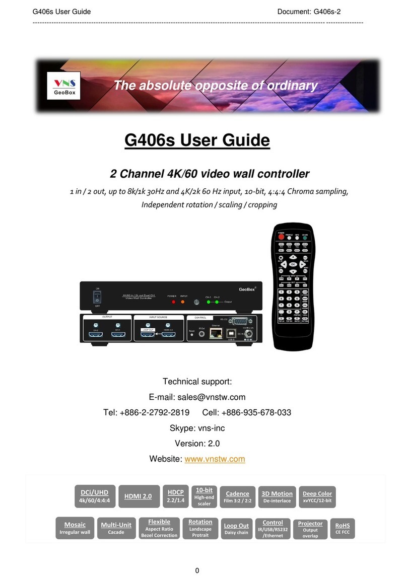
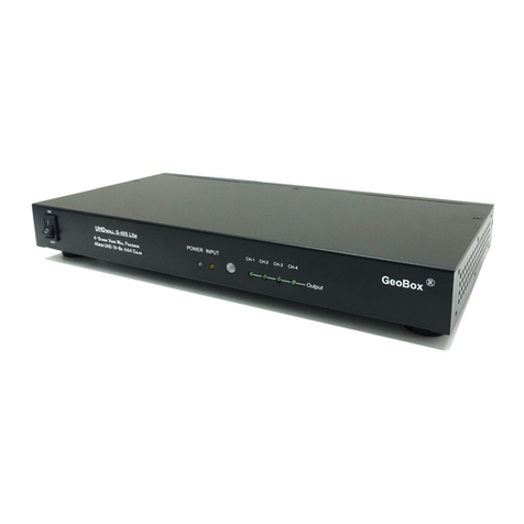
VNS G-413 User manual

G413 User Guide Document: G41302
-------------------------------------------------------------------------------------------------------------------------------------------
1
G-413 User Guide
Quad channel creative video wall controller
25 editable preset display modes
Custom modes with LCD at any angle and position
PIP/POP
Multi-unit cascade
Flexible aspect ratio and display region adjustment
Seamless looping playback with different display modes
RC-400
The absolute opposite of ordinary

G413 User Guide Document: G41302
-------------------------------------------------------------------------------------------------------------------------------------------
2
Table of Contents
1 Introduction……………………………………………………………..……………......…...…………. 5
2 Features.........…………………………………………………………..………….…….........…………. 6
3 Helpful tips for installation and operation…………………………………….…..…..................... 8
4 Outlook and main functions………………………………………..….......……………...………….. 9
5 Function in remote controller…………………………………………………………………………. 9
6 Basic concept for video wall configuration………………………………………………………… 10
7 Preset display modes……………………………………………..…………….…........…….............. 11
7.1 Introduction.…………………….……………………..……………........………………………. 11
7.2 LCD (TV) selection for Preset Modes ...…….……………………...……….……..........….. 11
7.3 Select Preset Display Modes through OSD……….……….....….………..……………….. 11
7.4 Preset display mode list…………………………………….……….….....……..……………. 13
8 Galign2 PC tool……...…………………………….….……......…..................................................... 18
8.1 Introduction….………………………………………………………..…......………………….... 18
8.2 Preparation for Galign2 operation…..……………………………………...…....…………… 18
8.3 Connection…………………………………………..…......................................................… 18
8.4 Prepare coordinate value off-line………………………………………..……...……………. 18
8.5 Galign2 PC tool operation…………………………………………………..…....................... 18
9 Preset Mode editing via Galign2 PC tool………………………………………….......................... 23
9.1 Select Preset Mode via remote controller or WebGui……………………….................... 23
9.2 How to read back Preset Mode setting value……………………..................................... 23
9.3 Reset Preset Mode setting……………………………………………………....…………….. 24
9.4 Real Time editing for Preset Mode……………………………………….....…….………….. 24
9.5 Image position adjustment in each LCD…………………………………………………..… 24
9.6 Aspect Ratio adjustment……………………………………………………………………….. 24
10 Preset Mode editing via remote controller…………………………………………………………. 25
10.1 Select Preset Mode via remote controller…………………………………………………… 25
10.2 Procedures for Preset Mode editing…………………………………………………………. 25
11 Preset Mode application case study………………………………………………………………… 27
11.1 Preset Mode: Mode 01………………………………………………………………………….. 27
11.2 Preset Mode 18 with two G413 cascade…………………………………………………….. 28
11.3 More example for Preset Mode cascade……………………………………………………. 30
12 Create custom display mode through OSD menu ……………………….………………………. 31
12.1 Select the location to store custom display mode—[Mode Index]…………………….. 31
12.2 Input coordinates for [Top LH] and [Top RH] corners in each TV……………………… 31
12.3 Image position [Shift] in H&V directions……………………………………………………. 32
12.4 Change aspect ratio, position & background color—[Ratio]……………………………. 32
12.5 Looping playback with different display modes…………………………………………… 36
12.5.1 Example for looping playback settings……………………………………………….. 37
12.5.2 Procedures to create looping playback modes……………………………………… 38
13 Detailed Procedures to create custom display mode…………………………………………….. 39
13.1 Introduction………………………………………………………………………………………. 39
13.2 Select Preset mode from OSD………………………………………………………………….. 39
13.3 Collect coordinates from design drawing……………………………………………………. 39
13.4 Collect coordinates from video wall picture…………………………………………………. 41
13.5 How to input coordinates for each LCD………………………………………………………. 44

G413 User Guide Document: G41302
-------------------------------------------------------------------------------------------------------------------------------------------
3
13.5.1 Upload coordinates via remote controller……………………………………………... 44
13.5.2 Upload coordinates via Galign2 PC tool……………………………………………….. 45
14 Important technical issues and trouble shooting
14.1 Prevent LCD from burn-in mark………………………………………………………………… 46
14.2 How to increase portrait display mode resolution………………………………………….. 47
14.3 How to determine signal resolution for entire video wall …………………………………. 48
14.4 How to show entire operation menu in irregular video wall………………………………. 48
15 OSD menu and functions……………………………………………………………………………….. 49
15.1 [Picture] color adjustment………………………………………………………………………. 49
15.2 [Image Setup] for VGA input……………………………………………………………………. 50
15.3 [Image Properties]………………………………………………………………………………… 50
15.3.1 [Scaling] (aspect ratio selection)……………………………………………………….. 51
15.3.2 [Output] resolution setting……………………………………………………………….. 51
15.3.3 Image [Orientation]………………………………………………………………………… 51
15.3.4 PIP/POP setting…………………………………………………………………………….. 52
15.4 [Video Wall] setting………………………………………………………………………………. 54
-- [Mode Index]—please check chapter 12…………………………………………………….. 31
-- [Mode Type]—please check chapter 10…………………………………………………….. 25
15.4.1 [Zoom]—split the image for cascade application……………………………………. 55
15.4.2 [Pan]—assign image for each G413 in cascade application……………………….. 55
15.4.3 [Overlap]—adjust image location and cropping area……………………………….. 56
15.4.4 [Position]—image position adjustment in entire G413……………………………… 57
15.5 [Options]—OSD miscellaneous functions…………………………………………………… 57
15.5.1 [Information]: System Information…………………………………........…….............. 57
15.5.2 [Language]: OSD language……………………………………………..…..................... 57
15.5.3 System [Reset]……………………………………………………………..….................... 58
15.5.4 [Accessibility]………………………….......……………………………………................ 58
15.5.4.1 [Menu Time Out]—OSD time ………….......………………………….…........... 58
15.5.4.2 [Logo Time out]—splash screen time………......…………………..…........... 59
15.5.4.3 [Standby Time]—auto shutdown time……………......……………..…........... 59
15.5.4.4 [Black screen]—background color when no signal input........................... 59
15.5.5 [Setting]……………………………………………………………………......…................ 60
15.5.5.1 Audio [Mute]…………………………………………………………......…........... 60
15.5.5.2 [DVI Output]………………………………………………………………………… 60
15.5.5.3 [Box ID]—for system control.......................................................................... 60
15.5.5.4 [Frame Sync]—frame lock and free-run synchronization mode………….. 61
15.5.5.5 [Profile]—save/load user settings......…………………………….………........ 61
15.5.5.6 [Network]………………………………….....……………………………….......... 62
15.5.5.6.1 [RS232] setting………………………….....……………………………. 62
15.5.5.6.2 [Ethernet] settings....……………..…………...................................... 62
15.5.5.7 [EDID] setting............................................................................……….......... 64
16 Trouble shooting…………………………………………………………………………………………. 65
17 Technical support………………………………………………………………………………………… 67
18 Safety precaution and maintenance………………………………………………………………….. 67
19 Specification………………………………………………………………………………………………. 68
20 Revision history………………………………………………………………………………………….. 71

G413 User Guide Document: G41302
-------------------------------------------------------------------------------------------------------------------------------------------
4
Disclaimer/Copyright Statement
Copyright 2019, VNS Inc. All Right Reserved
This information contained in this document is protected by copyright. All rights are reserved by VNS Inc.
VNS Inc. reserves the right to modify this document without any obligation to notify any person or entity of such revision. Copying,
duplicating, selling, or otherwise distributing any part of this document without signing a non-disclosure agreement with an authorized
representative of VNS Inc. is prohibited. VNS Inc. makes no warranty for the use of its products and bears no responsibility for any error
of omission that may appear in this document.
Product names mentioned herein are used for identification purposes only and may be trademarks of their respective companies.
Limited Warranty and RMA statement
This device is designed and tested to the highest standards and backed by two years’ parts and labor warranty. Warranties are effective
upon the first delivery date to the end customer and are non-transferable. Warranty related repairs include parts and labor, but do not
include repair of faults resulting from user negligence, special modifications, abuse (mechanical damage), shipping damage, and/or
other unusual damages. The customer shall pay shipping charges when the unit is returned for repair. Manufacturer will pay shipping
charges for return shipments to customers.
Manufacturer does not assume responsibility for consequential damages, expenses or loss of revenue, inconvenience or interruption in
operation experienced by the customer. Warranty service shall not automatically extend the warranty period.
User can pay extension fee to extend the warranty period. Please contact us for more details. In the event that a product needs to be
returned for repair, inform manufacturer and ask for a Return Material Authorization number.
FCC/CE statement
Note: This equipment has been tested and found to comply with the limits for a Class A digital device, pursuant to Part 15 of FCC Rules.
These limits are designed to provide reasonable protection against harmful interference in a residential installation. This equipment
generates, uses and can radiate radio frequency energy and, if not installed and used in accordance with the instruction, may cause
harmful interference to radio communications. However, there is no guarantee that interference will not occur in a particular installation.
If this equipment does cause harmful interference to radio or television reception, which can be determined by turning the equipment off
and on, the user is encouraged to try to correct the interference by one or more of the following measures:
Reorient or relocate the receiving antenna.
Increase the separation between the equipment and receiver.
Connect the equipment into an outlet on a circuit different from that to which the receiver is connected.
Consult the dealer or an experienced radio/TV technician for help.
Notice:
(1) An Unshielded-type power cord is required in order to meet FCC emission limits and also to prevent interference to the nearby radio
and television reception. It is essential that only the supplied power cord by used.
(2) Use only shielded cables to connect I/O devices to this equipment.
(3) Changes or modifications not expressly approved by the party responsible for compliance could void the user’s authority to operate
the equipment.

G413 User Guide Document: G41302
-------------------------------------------------------------------------------------------------------------------------------------------
5
1 Introduction
VNS creative video wall controller G413 is world unique and the first pure hardware solution that
can create all kinds of display modes through IR remote controller or simple PC tool. 25 Preset Modes can
be selected through OSD. These Preset Mode can be further edited to meet user’s different requirements.
Conventional low-cost monitor with different dimension, resolution and bezel size can be used as display
devices. The LCD can be installed at any angle and position. User can install LCD first, then crop the
required image for each LCD by remote controller or PC tool.
G413 is 4 screen video wall controller with PIP/POP function and supports up to 8k/1k 30Hz and
4k/2k 60hz input signal. HDMI 2.0 loop out port is available for daisy chain connection. It can be cascaded
to create large scale video wall.
Dynamic aspect ratio and position adjustment for entire video wall are special features of G413.
User has flexibility in seamless showing different cropping area or aspect ratio on the video wall with
different time interval. This function can be used to highlight specific image region or to show special effect
on the video wall dynamically from the same content. It also provides programmable background color in
video wall blanking area if the content is not full screen.
System setup and control can be executed through IR remote controller, RS232, USB or Ethernet.
Dual power supply systems are designed in G413. User can use AC 100-240V or DC12V. When AC is
applied, there will be one DC12V 1A output as the power supply for signal extender.
G413 is designed with highest industrial standard for 7/24 working environment. It provides a
simple, flexible and reliable solution for creative video wall.

G413 User Guide Document: G41302
-------------------------------------------------------------------------------------------------------------------------------------------
6
2 Features:
1) Flexible video source connection
- 2x HDMI and 1x DP: support up to 8k/1k @30 Hz or 4k/2k @60Hz.
- 1x VGA: support up to WUXGA resolution.
2) Quad channel outputs
4x FHD HDMI outputs for connecting with 4x LCD or conventional TV / monitor.
3) System cascade
One HDMI 2.0 loop out port for multiple unit cascade for large scale video wall. No HDMI splitter is
required.
4) Pre-defined display modes
25 pre-defined creative display modes that can be selected through OSD. Preset modes can be
further modified to meet user’s requirements.
5) Create any irregular video wall by user
- User can create any display mode for regular, portrait and irregular video wall using LCDs with
different dimension, resolution and bezel. Use can crop the required image for each LCD
through inputting the coordinates of Top Left and Top Right corners in each monitor.
- Galign2 PC tool and remote controller are available to upload coordinates into G413.
- Windows “Paint” software can be used to capture the coordinates in each monitor.
6) Flexible aspect ratio control
Flexible aspect ratio control across entire video wall through OSD menu is integrated. User can
decide how to display content on the video wall if the content can’t match video wall aspect ratio.
The adjustment range is from 25% to 200% independently in horizontal and vertical directions.
7) Anyplace cropping
User can crop any image location to be displayed in monitor.
8) Flexible position adjustment
The combination of flexible aspect ratio control and position adjustment (25% to 200%) will allow
user to determine the best image region for the display on the video wall.
9) Auto looping playback
User can setup up to 10 display modes from the same display content and looping playback with
selectable time interval (1 second to 600 seconds). This function can be used to highlight specific
image region to show special effect on the video wall dynamically from the same content.
10) Any display devices
Conventional TV/monitor can be used at top/bottom, LH/RH flip position to balance TV bezel
difference between top and bottom edges.

G413 User Guide Document: G41302
-------------------------------------------------------------------------------------------------------------------------------------------
7
11) Programmable EDID: preset 13 EDID timing + programmable EDID setting to optimize input
resolution. Programmable EDID has below resolution range: H: 1024-3840, V: 720-2400
12) LCD burn-in mark protection: Auto image position shift to prevent LCD from burn-in mark.
13) PIP function: Picture in Picture from two selected signal sources with flexible position and image
size (320*180 up to 1920*1200). PIP image can be further adjusted by Overlap function to get
various size and shape.
14) Main and PIP image can be swapped to cover full screen across entire video wall.
15) POP function: Image Side by Side display with full screen or maintain original aspect ratio. Two
POP contents can be displayed on LCDs at RH/LH or up/down positions with monitor at landscape
direction.
16) System setup: User can setup the system through IR remote controller, USB or Ethernet. User can
connect G413 to WiFi router and execute system setup and control via WiFi through any device
connected with WiFi router. WebGui and Galign2 PC tool is available for Ethernet operation.
17) System control: user can control G413 through IR remote controller, USB, RS232 and Ethernet.
18) Auto power on/off control: When no input signal is detected, GeoBox can auto-turn off output
signal. Once input signal is detected, it will auto-turn on GeoBox and send out signal again. It is
convenient for system power on/off control.
19) Selectable background color: When adjusting aspect ratio, user may see some blank background
in the video wall. User can select background color by OSD.
20) Custom settings: Up to 10 different display modes settings in the same signal source can be
stored. 5 display Profiles with different input source and PIP/POP setting can be stored. User can
recall at any time through remote controller, RS232, USB or Ethernet.

G413 User Guide Document: G41302
-------------------------------------------------------------------------------------------------------------------------------------------
8
3 Helpful tips for installation and operation
1) User can set Box ID for independent control among multiple GeoBox by remote controller.
- 851: control GeoBox ID No. 1
- 853: control GeoBox ID No. 3
- 850: simultaneous control for all GeoBox
- User will see flashing LED on front panel after press 85x number keys. It means the GeoBox
with flash LED is locked and will not be controlled by remote controller.
2) To use Galign2 PC tool through USB or Ethernet for the setting is recommended and use remote
controller for image position fine-tune.
3) GeoBox test pattern is important for video wall image position adjustment. It can be downloaded
from website at www.vnstw.com.
4) There are 25 preset display modes that can be selected through OSD menu. User can select
preset display modes and modify as need. It will save the time for the setup.
5) If user wants to create his own creative video wall which is totally different from preset mode, the
quickest way is to install the LCD first, take a photo of the video wall, crop and get coordinate
through Windows Paint in top left and top right corners in each LCD, then input the coordinates
into G413 through Galign2 PC tool to get the result.
6) User can use below hotkeys in remote controller for image fine-tune:
- [Shift]: to shift image position in H&V without changing image size and direction.
- [Top RH] / [Top LH]: to change image size, position and display angle
- [Ratio]: to enlarge or shrink the image for full screen display or aspect ratio change
- [Position]: after [Ratio] adjustment, user can shift entire video wall image position.
7) OSD Lock / Unlock: When continuously press [MENU] key in IR Remote Controller for 5 seconds,
the OSD function will be locked (LED on front panel will be flashing). To press MENU key for 5
seconds again, it will unlock OSD.
8) Poor signal cable connection or long cable may cause noise or discontinue on the display.
Replace a new cable may solve the problem. Normal HDMI connection with good cable can be up
to 15m. 4k/60 input signal will be more sensitive to cable quality.
9) User may not see complete image for signal source setup. User can use remote controller to select
one display Mode # which is not stored any setting to display full image. After finish signal source
setup, then return to the working Mode for further operation.
10) If the video wall is more than 4 LCD, please apply 4k content together with Preset Mode to get high
video wall resolution. Please see more details in Chapter 11.

G413 User Guide Document: G41302
-------------------------------------------------------------------------------------------------------------------------------------------
9
4 Outlook and main functions
5 Functions in Remote controller
Output port selection (TV1-TV4)
Store location for Display modes
Video wall Main Menu [VW]
Entire video wall position adjustment [P]
To adjust image position at H&V without changing image size [Shift]
Entire video wall Aspect Ratio adjustment [R]
Top Right coordinate menu [TR]
Top Left coordinate menu [TL]
Procedures for determine each LCD image position
1) Select display Mode #—Mode 1~Mode 4 (please select Mode 5 to Mode
10 through OSD)
2) Select output port—TV1~TV4
3) Click Top Left [TL] and input coordinates
4) Click Top Right [TR] and input coordinates
5) Click [Shift] and adjust image position if necessary
6) Adjust aspect ratio if necessary: [Ratio]
7) Adjust image position if necessary: [Position] (after aspect ratio change)
8) No special input sequence is required among TV1~TV4.
Output Ports
TV1/TV2
Output Ports
TV3/TV4
Input Ports Control ports
USB, IR, IP
Input Status Input Status
Loop out

G413 User Guide Document: G41302
-------------------------------------------------------------------------------------------------------------------------------------------
10
6 Basic concept for video wall configuration
11) [Top RH] & [Top LH] X/Y coordinates determine the image position
- Image allocation for each LCD is based on [Top RH] & [Top LH] corner X&Y coordinate value
in 1920*1080 coordinate system. The coordinate system must keep 16:9 aspect ratio.
- Original point (0,0) is located at Top Left corner. (1920, 1080) is located at Bottom Right
corner.
- No matter the LCD is located at any location, once it is 16:9 aspect ratio, user can assign the
image location to each LCD through [Top RH] & [Top LH] X&Y coordinates.
- Through [Top RH] & [Top LH] coordinates change, user can adjust the image size, rotation
angle and position in each output.
- User can setup creative video wall through design drawing and calculate the distance to
convert into X&Y coordinates or take photo of the video wall, then convert it into X&Y
coordinates through Window [Paint] software.
- After collect [Top RH] & [Top LH] X&Y coordinates, user can upload X&Y values by remote
controller or Galign2 PC Tool. Galign2 PC tool is recommended for easier and quicker setup.
12) [Shift] function is to adjust X or Y values at [Top RH] & [Top LH] at the same time resulting image
shifting in H&V direction without change image size. It applies to each output for position fine-tune.
13) [Ratio] & [Position] functions allow user to change complete video wall image aspect ratio and
image position.

G413 User Guide Document: G41302
-------------------------------------------------------------------------------------------------------------------------------------------
11
7 Preset Display Modes
7.1 Introduction
LCD panel used in Preset Mode must have the same size and 16:9 aspect ratio.
Preset mode doesn’t take LCD panel bezel size into consideration. It is good for slim bezel under
3.5mm active to active bezel size. If the bezel is larger, user may need to do further bezel
correction through position fine-tune in each LCD.
If the preset mode with LCD at 0/90/180/270 degrees, it will be less sensitive to bezel size. User
will still see acceptable video quality even the bezel is up to 5-10mm width.
The preset modes will fit complete source image with full screen across entire video wall. It will
not consider the aspect ratio of the signal source.
User can also use [Overlap] function under [Video Wall] menu to adjust the cropping area of the
signal source for entire video wall.
User can use [Ratio] & [Position] OSD menu to adjust final aspect ratio and position in the video
wall based on the image that is cropped through [Overlap] function.
Customized Mode can be created with all kind of LCD without size and bezel limitations.
7.2 LCD (TV) selection for Preset Mode
Type of LCD: low cost 16:9 LCD or TV can be used. No need to have matrix control feature.
All the LCD panels used in the same video wall must have the same size and 16:9 aspect ratio.
Some Display Modes support TV at top down flip position to balance the bezel difference.
Output resolution: the default output resolution is 1920x1080 @60Hz in each output channel. The
LCD must be able to support FHD input timing.
7.3 Select Preset Display Modes through OSD

G413 User Guide Document: G41302
-------------------------------------------------------------------------------------------------------------------------------------------
12
User can use remote controller to select preset display modes.
[Video Wall] [Mode Type] select display mode
1st mode is to output 4 signals same as signal source. It is similar to 1x4 HDMI splitter.
User can switch the display angle in each display mode by 90/180/270 degrees. It will create
different display mode.
……………………………………………………………………………………………………

G413 User Guide Document: G41302
-------------------------------------------------------------------------------------------------------------------------------------------
13
7.4 Preset display mode list
User can select Preset Mode as base
to create customized display modes.
Image aspect ratio can be adjusted
through [Ratio] & Video Wall [Overlap]
function.
Below Preset Modes don’t consider
Bezel size. User can use [Shift], [Ratio]
and/or [Top LH] / [Top RH] coordinate
adjustment function in remote controller
or PC tool to get accurate bezel
correction and image location.
Mode 0 - Duplicate Mode
When system is reset, it will show 4 duplicated
windows same as signal source in all outputs.
Mode 1 – 2x2 (Ratio 16:9)
Mode 2 – 2x2 with top two TV upside down
(Ratio 16:9)
Mode 3– 4x1 (Ratio 2.25)
Mode 3A – 1x4
Apply 90〫 signal source or
rotate image at 90〫 to get
normal viewing angle from
Mode #3.

G413 User Guide Document: G41302
-------------------------------------------------------------------------------------------------------------------------------------------
14
Mode 4 – 3x1 (Ratio 1.69)
(#4 output will show full screen image)
Mode 4A – 1x3
Mode 5– 2x2 with TV2 & TV4 shift down 1/2 panel
height (Ratio 1.42)
Mode 6– 2x2 with TV2 & TV4 shift down 1/2 panel
height (Ratio 1.42)
Mode 7 – 2x2 with clockwise 15〫rotation (Ratio
1.7)
Mode 8 –2x2 with clockwise 15〫rotation and
TV1 & TV2 at upside down position (Ratio 1.7)
Apply 90〫 signal source or
rotate image at 90〫 to get
normal viewing angle from
Mode #4.

G413 User Guide Document: G41302
-------------------------------------------------------------------------------------------------------------------------------------------
15
Mode 9– 2x2 with TV3 & TV4 Right shift 1/2 panel
width (Ratio 2.22)
Mode 10– 2x2 with TV3 & TV4 Right shift 1/2
panel width (Ratio 2.22)
Mode 11 –(Ratio 1.89)
Mode 12 – (Ratio 5.33) for 3x3 application
Mode 12A
Mode 13 –TV2 & TV4 Down shift with 1/4 panel
height (Ratio 1.8)
Mode 14 – TV4 Down shift 1/4 panel height (Ratio
1.8)
Apply 90〫 signal source or
rotate image at 90〫 to get
normal viewing angle from
Mode #12.

G413 User Guide Document: G41302
-------------------------------------------------------------------------------------------------------------------------------------------
16
Mode 15 – 75〫counterclockwise rotation (Ratio
1.77) (#4 output will show full screen image)
Mode 16 – (Ratio 1.16)
Mode 17 – 45〫counterclockwise (Ratio 1.0)
Panel location at half position
Mode 18 – 45〫clockwise rotation (Ratio 1.0)
Mode 19 – 45〫clockwise rotation (Ratio 1.1)
Panel top and bottom at the same height.
Mode 20 – 45〫clockwise rotation (Ratio 1.33)

G413 User Guide Document: G41302
-------------------------------------------------------------------------------------------------------------------------------------------
17
Mode 21 – (Ratio 1.0)
Mode 22 (Ratio 1.0)
Mode 23 (Ratio 1.0)
Mode 24 – 45 degrees rotation (Ratio 1.0)

G413 User Guide Document: G41302
-------------------------------------------------------------------------------------------------------------------------------------------
18
8 Galign2 PC tool
8.1 Introduction
Galign2 is specific PC tool for G413. User can input coordinates for [Top RH] & [Top LH] corners
of the image in each LCD to get creative video wall. System setting, control and code update can
also be executed through Galign2.
If user selects Preset display mode from OSD, user can read back the setting parameters and
execute further editing to match what he needs.
8.2 Preparation for Galign2 operation
PC with Galign2 PC tool: please download from website at:
http://www.vnstw.com/otherfile/8/file316-1-20190820221815-65.zip
USB Type B cable or Ethernet cable together with switcher/Hub/Router.
Apply source signal to G413 with GeoBox Video Wall test pattern. Please download pattern from:
http://www.vnstw.com/otherfile/14/file314-1-20190820122537-99.png
The test pattern has number scale on it and user can estimate from the test pattern the adjusting
pixels to move the image to correct position.
8.3 Connection
For system setup, we propose to use USB through USB Type B connection.
If the box is far away from installation site, Ethernet connection is recommended. G413 default IP
address is 192.168.0.100. User can change it through OSD, Web Gui or Galign2 PC tool.
Direct connection through UTP cable: user needs to set PC/NB with the same IP segment,
such as 192.168.0.10x.
WiFi router: user can connect G413 to WiFi router through LAN port and select DHCP or
static IP for the connection in OSD. Once PC/NB connects with this WiFi router, user can find
G403 and execute Galign2 operation.
When multiple units of G413 are used, user can set different IP address in each G413 and
control multiple units at the same time through different IP address.
8.4 Prepare coordinate value off-line
User can operate Galign2 without connecting with GeoBox. If the coordinates value for each LCD
are available, user can input the value into Galign2 and save it in PC. After connecting with
G413, user can load it from PC and upload the coordinate values into G413 by [Write] command
and see the final result immediately.
8.5 Galign2 PC Tool operation

G413 User Guide Document: G41302
-------------------------------------------------------------------------------------------------------------------------------------------
19
TV1-TV4 represents G413 output ports from CH-1 to CH-4.
For Preset Mode, user needs to follow the sequence, location and direction in Preset Mode menu
to install the video wall.
If no PC for Galign2 PC tool operation, user can still use remote controller or WebGui to execute
coordinate key-in, position fine-tune, aspect ratio and position adjustment...etc.
Below item # corresponds with the RED # in Galign2 operation window.
(1) [Connect]:
- After select type of connection, click [Connect] to connect Galign2 with G413. Default connection type
is [USB].
- After open [Galign2], all the parameters will be reset to default value. User can load previous setting
by [Load Setting] (15) from PC or [Read] (3) function from video wall or Preset Mode.
(2) After connection, user will see model # and output resolution. Default output resolution is 1080P/60Hz.
(3) [Read]:
- Functions: a. Read back parameters from video wall setting. b. Read back parameters from Preset
Mode which is selected by remote controller. C. Read back parameters from display Mode (11).
- After user select Preset Mode from OSD through remote controller, when user click [Read], Galign2
will read back the parameters of Preset Mode and save to Mode #1 (default Mode # is 1). If user
selects other Mode # and execute [Read] command, it may not read back Preset Mode parameters.
2
3
4
4
8
7
6
Connect
12
13
14
15
9
10
11
16
5
17
18
19
4
4
4
4
4
4
1

G413 User Guide Document: G41302
-------------------------------------------------------------------------------------------------------------------------------------------
20
- After Read back parameters, user can select another Mode # and use [Write] (5) command to save to
other Mode #. User can do further editing for Preset Mode and create customized display mode.
- If user saves the setting into display Mode (11), user can select the display Mode and click [Read] to
read back the setting. The video wall will stay the same until [Write] command is executed.
(4) Locations for Key-in or editing the coordinates of Top Left corner and Top Right corner for TV1-TV4. The
coordinates can be captured from Preset Mode, video wall picture or project plan files. If user checks
[Diagram] (7), user will see the adjusting result in the Diagram but not in the Video wall before executes
[Write] (5) command. User can also CHECK [Real Time] (6) to see the result in real time in video wall.
(5) [Write]
- After finish all settings in Galign2, the image is still controlled by PC. User needs to use [Write]
command to upload all parameters into G413.
- User needs to disable [Real Time] function before execute [Write] command.
- User can save up to 10 different display Modes. Please select [Mode #], then click [Write] to save
Galign2 parameters. The settings can be saved into any display Mode # and can be duplicated.
- It only saves the image settings showed in Galign2 but not includes input ports, color, PIP setting,
EDID…which will be saved in Profile Index.
- If user wants to show specific Mode settings, please select Mode #, click [Read] to read the
parameters, then click [Write] button to upload the settings to video wall and see the final result. User
can use remote controller and click Mode # (Mode #1~#4) to show the setting in each Mode # directly.
(6) [Real Time]:
- When user executes editing Preset Mode or creates new custom display mode, please check [Real
Time] so that user can see the image change while changing parameters.
- [Real Time] shall be disabled when user wants to key-in coordinate data or [Write] the result to
GeoBox.
(7) [Diagram]:
- If user check [Diagram], there will be a diagram showed up near Galign2 window.
- This diagram will update real time while user changes the coordinate values in coordinates. The
[Warp Ratio] and [Warp Position] changes will not be showed in the diagram.
- Below left diagram is Preset Mode selected by OSD and the RH diagram is in Galign2. Please note
that the color in each LCD is corresponding the output channel (TV1-TV4) in Galign2 window.
This manual suits for next models
1
Table of contents
Other VNS Controllers manuals
Popular Controllers manuals by other brands
Broan
Broan NuTone Overture BIAQWC100P manual

Slam Specialties
Slam Specialties MC.2 installation instructions
Technische Alternative
Technische Alternative UVR67 quick guide
Titan Controls
Titan Controls Helios 14 instruction manual

Speaka Professional
Speaka Professional 2256178 operating instructions
Bacharach
Bacharach MVR-SC quick start guide
Emerson
Emerson Dixell XR44CX Installing and operating instructions
Motrona
Motrona MC700 manual
Uponor
Uponor Smatrix Base PULSE quick guide
Milesight
Milesight UC51 Series user guide
Loctite
Loctite EQ CL42 operating manual
Victaulic
Victaulic FireLock NXT 769 Series Installation, Maintenance, and Testing Manual

