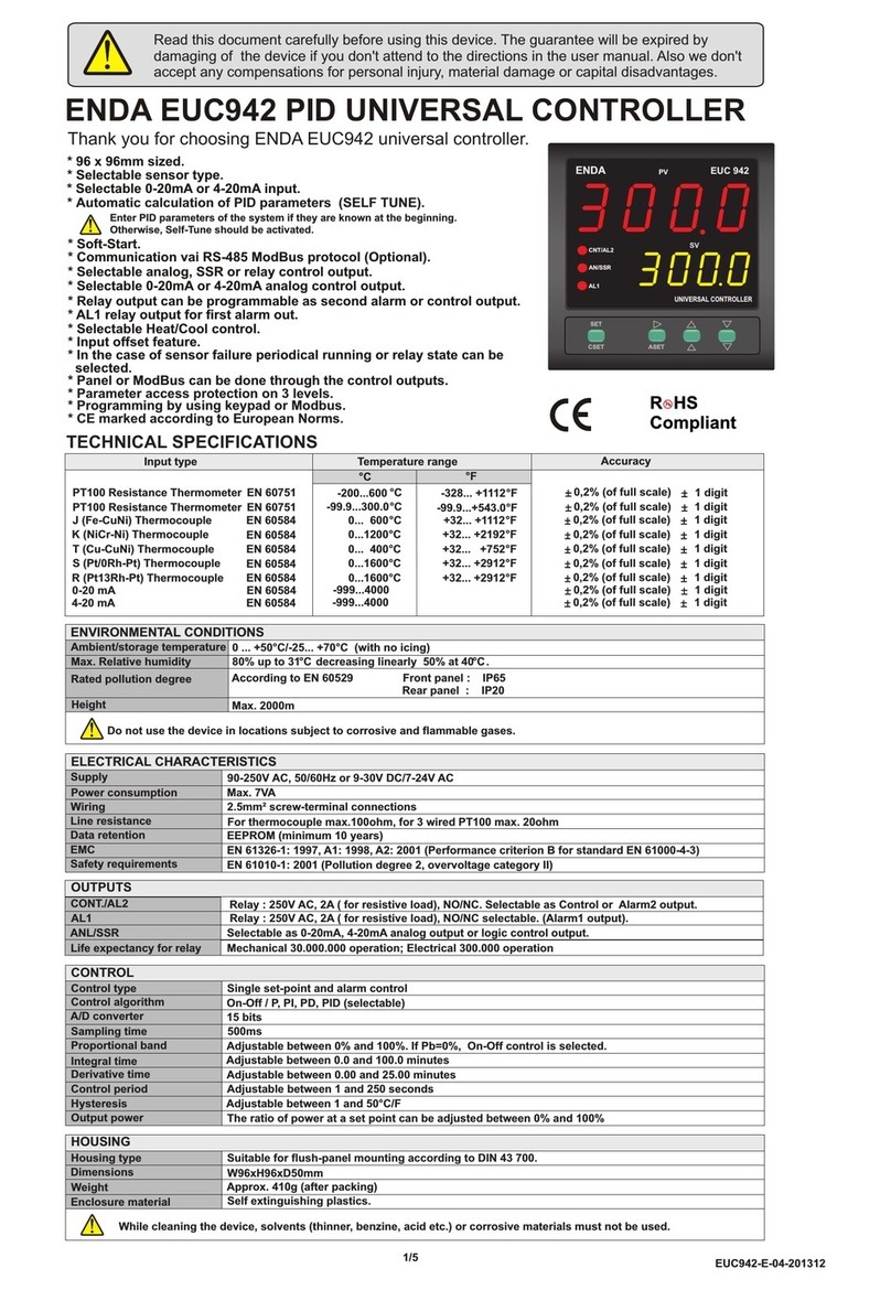
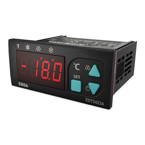
ENDA EDT3011 Series User manual

ENDA EDT3011 COOLING / DEFROST CONTROLLER
1 / 2
77 x 35mm sized
Single NTC prob input
Additional offset feature for input
Defrosting duration and interval time settings
Delay time and minimum operating time settings for
compressor protection
Compressor or door alarm control via digital input
Upper, lower and delay time settings for alarm
In case of probe failure, output status can be set to ON,
OFF or periodic
Upper and Lower setpoint value limits can be adjusted
Temperature unit can be selected as °C or °F
CE marked according to European Norms
Panel Cut-out
71,5mm
29mm
CONNECTION DIAGRAM
ELECTRICAL CHARACTERISTICS
230V AC +10% -20%, 50/60Hz or 12/24V AC/DC ±10% or 9-30V DC / 7-24V AC SMPS
Max. 3VA
Power connection : 2.5mm² screw-terminal, Signal connection : 1,5mm² screw-terminal connections
EN 61326-1: 2013 (Performance criteria B has been satisfied for EN 61000-4-3 standard)
EEPROM (Min. 10 years)
±1% - 1sec.
Max. 100ohm
EN 61010-1: 2010 (Pollution degree 2, overvoltage category II ).
Suitable for flush-panel mounting according to DIN 43 700.
W77xH35xD61mm
Approx. 215g (after packing)
Self extinguishing plastics
Single set-point and alarm control
12-bit accuracy, 100ms sampling time
Adjustable between 0.1 and 15.0 °C/F
Max.2000m
KEEP AWAY device from exposed to corrosive, volatile and flammable gases or
liquids and DO NOT USE the device in similar hazardous locations.
80% Relative humidity for temperatures up to 31°C, decreasing linearly to 50% at 40°C.
0 ... +50°C/-25 ... +70°C (with no icing)
According to EN 60529 ; Front Panel : IP65, Rear Panel : IP20
Avoid any liquid contact when the device is switched on.
DO NOT clean the device with solvent (thinner, gasoline, acid etc.) and / or abrasive cleaning agents.
Scale Range Accuracy
EN 60751
-60.0...150.0 °C -76.0...302.0°F
± 1% (Full scale) ± 1 digit
Supply
Power Consumption
Wiring
Line Resistance
Data Protection
Time Accuracy
EMC
Safety Requirements
HOUSING
Housing Type
Dimensions
Weight
Enclosure Material
CONTROL
Control type
Kontrol yöntemi
A/D converter
Hysteresis
ENVIRONMENTAL CONDITIONS
INPUT
Height
Ambient / Storage Temperature
Relative Humidity
Protection Class
Input Type
NTC Resistive Sensor
3.5 digit, 7-segment 19mm red LED
Scale
For 8A : NO and NC 250V AC, 8A (resistive load), Control output.
For 20A : NO 250V AC, 20A (resistive load), Control output.
For 8A : Mechanical 30.000.000; Electrical 300.000 operation. 250V AC, 8A (resistive load).
For 20A : Mechanical 30.000.000; Electrical 100.000 operation. 250V AC, 20A (resistive load).
OUTPUT
Life expectancy for relay
C1 Output
1
3
3
4
Covers
For mounting device ;
Push the device in direction 1
Order Code : EDT3011 - - -
1 2 3
1- Supply Voltage
230......230V AC
024........24V AC/DC
012........12V AC/DC
SM........9-30VDC/7-24VAC
2- Output Selection
08.....8A Relay output
20.....20A Relay output
3- ModBus
Blank.....N/A
RS.........ModBus
(Specify at Order)
Read this document carefully before using this device. The guarantee will be expired by device
damages if you don't attend to the directions in the user manual. Also we don't accept any
compensations for personal injury, material damage or capital disadvantages.
Thank you for choosing ENDA EDT3011 series cooling / defrost controller devices.
ENDA EDT3011 is intended for installation in control panels. Make sure that the device is used
only for intended purpose. The electrical connections must be carried out by a qualified staff
and must be according to the relevant locally applicable regulations. During an installation, all of the cables
that are connected to the device must be free of electrical power. The device must be protected against
inadmissible humidity, vibrations, severe soiling and make sure that the operation temperature is not
exceeded. The cables should not be close to the power cables or components.
SUPPLY:
NOTE:
184-253V AC
50/60Hz 4VA
Line
Neutral
230V AC
Supply
Switch
Note:
Cable size: 1,5mm²
Fuse
F 100 mA
250V AC
Fuse should
be connected
1) Mains supply cords shall meet the requirements of
IEC 60227 or IEC 60245.
2) In accordance with the safety regulations, the power
supply switch shall bring the identification of the
relevant instrument and it should be easily
accessible by the operator.
11
12
Holding screw
0.4-0.5Nm
Equipment is protected throughout
by DOUBLE INSULATION.
DIMENSIONS
Note :
1) Panel thickness should
be maximum 7mm.
2) If there is no 60mm free
space at the back side of
the device,it would be
difficult to remove it from
the panel.
For removing device from panel :
- Push the flush-mounting clamps in
direction as shown in the figure.
Then, pull out the clamp in direction
SİSEL MÜHENDİSLİK ELEKTRONİK SAN. VE TİC. A.Ş.
Şerifali Mah. Y.Dudullu 34775
ÜMRANİYE/İSTANBUL-TURKEY
Tel : +90 216 499 46 64 Pbx. Fax : +90 216 365 74 01
url : www.enda.com.tr
Barbaros Cad. No:18
8 680 407 7224 40
C1
1 2 3 4 5 6 7 8 9 10
ENDA INDUSTRIAL ELECTRONICS
SN: XXXXXXXXX
EDT3011-230-08
DIGITAL THERMOSTAT
230V AC +10% -20%
50/60Hz 5VA
11 12
250V AC 8A
RESISTIVE LOAD
NTC
DOOR
SW.
MADE IN TURKEY
8 680 407 7224 57
C1
1 2 3 4 5 6 7 8 9 10
ENDA INDUSTRIAL ELECTRONICS
SN: XXXXXXXXX
EDT3011-230-20
DIGITAL THERMOSTAT
230V AC +10% -20%
50/60Hz 5VA
11 12
250V AC 20A
RESISTIVE LOAD
NTC
DOOR
SW.
MADE IN TURKEY
C1
1 2 3 4 5 6 7 8 9 10
ENDA INDUSTRIAL ELECTRONICS
SN: XXXXXXXXX
EDT3011-230-08-RS
DIGITAL THERMOSTAT
230V AC +10% -20%
50/60Hz 5VA
11 12
250V AC 8A
RESISTIVE LOAD
NTC
DOOR
SW.
MADE IN TURKEY
+-
AB
RS485
8 68040 7 72 2464
1
3
2
3
2
2
2
1
EDT3011-EN-02-191202
ENDA
TM
EDT3011-EN-02-191202

In order to access security
menu 311 should be entered
r0 C0
o1
r1 C2
P1
r2 C3
C5
P2
i1
i5
P5
C4
d0.
d3
d4
d8
-Cn -rE -CP -dE -AL -SC
S.Cd
Cn.s
rE.s
CP.S
dE.S
Al.S
SP.S
GENERAL SETTINGS TEMPERATURE SETTINGS COMPRESSOR SETTINGS DEFROST SETTINGS ALARM SETTINGS SECURITY SETTINGS
Programming Mode
Default
Value
Default
Value
Default
Value
Default
Value
Default
Value
Default
Value
2.0 1
P.YE
P.YE
P.YE
P.YE
P.YE
P.YE
0
0.0
-60.0
3
0.0
150.0 0
10
°C
n.c
3
t.d
10
8
30
d.no
0
Programming Diagram
If this key is pressed
for 2 seconds, SP
message appears on
display and access to
temperature settings.
Temperature value
4.0
SP
Runnig Mode
-18.0
C1 Set Value
-18.1 -18.2 -18.1
Default Value
0.0 If any key is not pressed for 4 seconds, "Running Mode" is entered.
d5
0
d6
1
Operating Temperature
Hysteresis.
It can be adjusted
between 0.1 and 15.0 .
Compressor Power-up
Delay Time
Can be adjusted
between 0 and 199
minutes.
Defrosting Interval.
It can be adjusted between 0
and 199 hours. If 0 is selected,
defrost is never performed.
See d8 parameter.
Defrost Running Time
It can be adjusted between 0
and 199 hours. If 0 is selected,
defrost is never performed.
Defrosting interval Type
Selection.
0 = Defrosting timer ( d0 )
counts during the device is
running.
1 = Defrosting timer ( d0 )
counts during the compressor is
running.
Indicator Value Selection
During Defrost.
0 = Cabin temperature is
displayed.
1 = Displayed if the cabin
temperature is below SP + r0 ,
otherwise SP + r0 is displayed.
When the defrost ends, the
display value does not change
until the cabin temperature falls
below SP + r0 .
P r o b e C a l i b r a t i o n
Can be adjusted between
-25.0 and 25.0
Minimum Temperature
Can be adjusted
between -60.0 and r2
Required Minimum Stop
Duration for Compressor
Can be adjusted between
0 and 199.
Maximum Temperature
Can be adjusted
between r1 and150.0 .
D e c i m a l N o t a t i o n
0 = Without decimal
0.0 = With decimal
Temperature Unit
°C = Celsius
°F = Fahrenheit
Digital Input Relay State
n.o = Will be activated when
switch position is closed.
n.c = Will be activated when
switch position is opened.
Digital Input Behavior
0 = No act.
1 = External alarm is active.
At the end of i7 time, iA
flashes on the screen until the
external alarm is OFF.
2 = External alarm is active.
At the end of the i7 time,
the compressor is stopped
until the external alarm is
turned off and iA flashes
on the display.
3 = Door is open.
Compressor is stopped until
the door closes and id
flashes on the screen when
i7 time is up.
Indicator Selection During
"Running Mode”
t.d = Indicates cabin
temperature.
SP.d = Indicates SP value Compressor Stop Time
In Case of Probe Failure.
Can be adjusted between
0 and 199.
-60.0
150.0
abs
AbS
120
30
15
15
A1
A4
A2
A5
A6
i7
pfa psC iA
___ aH id
___ al
A7
A8
Low Temperature
Alarm Set Value.
Can be adjusted between
-60.0 and 150.0°C.
Hysteresis value is
2°C / 4°F.
Hight Temperature
Alarm Set Value.
Can be adjusted between
-60.0 and 150.0°C.
Hysteresis value is
2°C / 4°F.
Low Temperature
Alarm Type Selection.
No = No alarm
rEL = Dependent on SP
value.
AbS = Independent alarm.
Hight Temperature Alarm
Type Selection.
No = No alarm
rEL = Dependent on SP
value.
AbS = Independent alarm.
Digital Input Delay Time
Can be adjusted between
0and 120 minutes.
Temperature Alarm
Delay Time.
Can be Adjusted
between 0 and 240
minutes.
High Temperature Alarm
Delay Time After Defrost.
Can be adjusted between 0
and 240 minutes.
CAUTION !
During defrost process, alarms will
not be activated.
If the door is open, the high
temperature alarm will not be active.
-Cn Menu Security Level
Non = Menu invisible.
P.YE = Can be modified.
P.np = Read only.
ERROR MESSAGES
Sensor Broken
(Cannot Communicate
with the Sensor ) NTC Sensor Short Circuit External Alarm
High Temperature Alarm Door Open
Measured Temperature
Above the Scale
Move ENDAKEY-RF towards the top left of the
device in direction 1 .
If this key is pressed
for 4 seconds,
“Programming Mode”
is entered.
First time pressed any of the
keys, temperature set value
appears by flashing.
And, temperatures set value can be adjusted by using keys.
Accessing to "Running Mode" from "Programming Mode" :
if no key is pressed within 30 seconds during “Programming Mode”,
data is stored automatically and "Running Mode" is entered.
Alternatively, by pressing key for 4 seconds, data is stored and
"Running Mode" is entered.
If this button is pressed for 2 seconds, device turned ON or OFF.
If this key is pressed for 1 second while the alarm buzzer is active,
buzzer is turned OFF. If this key is pressed for 4 seconds, the manual
defrost mode is entered or exited.
Required Minimum
Running Duration for
Compressor
Can be adjusted between
0 and 199.
Compressor Running
Time In Case of Probe
Failure.
Can be adjusted between
0 and 199.
Defrost Time Performed at
Power-up
d.no = Defrost not performed at
power-up
d.yE = Defrost performed at
power-up
Defrost Power-up Start Delay
Time
Can be adjusted between 0 and
199 minutes. Will be valid if ;
d4 = d.yE
While in a parameter menu, if
key is pressed for 2 seconds
“Programming Mode" is entered.
High Temperature Alarm
Delay Time After Power-up.
Can be adjusted between
0 and 240 minutes.
SETTING UP THE PARAMETERS
If key is pressed, the current value of the parameter appears by
flashing on the display.
After the setting up the parameters, if set key is pressed again,
adjusted parameter name appears on display.
By using “UP” or “DOWN” navigation keys, selected
parameter can be adjusted to the desired value.
During a parameter adjustment, If one of the or navigation key is
pressed continuously for 0.6 seconds, adjusted value to be changed increases or
decreases rapidly.
If it continues to press for longer than 0.6 seconds, hundered digits will increases or
decreases rapidly. If the key released and wait for a second, then process returns
to the units digit.
r2 50.0 49.9 50.0
Whilst in S.Cd = 0
parameter, by pressing and
held down key and
by pressed key for 3
seconds, dEF parameter is
displayed and the device
returns to default settings.
-rE Menu Security Level
Non = Menu invisible.
P.YE = Can be modified.
P.np = Read only.
-CP Menu Security Level
Non = Menu invisible.
P.YE = Can be modified.
P.np = Read only.
-dE Menu Security Level
Non = Menu invisible.
P.YE = Can be modified.
P.np = Read only.
-AL Menu Security Level
Non = Menu invisible.
P.YE = Can be modified.
P.np = Read only.
SP Menu Security Level
P.YE = Can be modified.
P.np = Read only.
If the pressed for 4 seconds, device switch to "Programming Mode". If you keep pressing the key for 6
seconds, then the message H.rd appears on display and device is moved to the reading position from the
ENDAKEY. In this case the device waits for the parameters to be read from ENDAKEY. In this case,
ENDAKEY should touching the upper left the corner of device and pressing the button on the ENDAKEY.
Parameters reading is performed with ENDAKEY the PyE is shown before return to the operating mode. If
reading is not performed, the device waits for 1 minute and returns to the "Running Mode".
Programing From the Device to ENDAKEY-RF
Programing With ENDAKEY-RF
If the button on the ENDAKEY is pressed and ENDAKEY will transfer the parameters to the device then
the PyE message is shown. And the device switches to the "Running Mode".
Measured Temperature
Below the Scale High Temperature Alarm
2 / 2
1
1
EDT3011-EN-02-191202
ENDA
TM

R / W
R / W
R / W
R / W
R / W
R / W
R / W
R / W
R / W
R / W
R / W
R / W
R / W
R / W
R / W
R / W
R / W
R / W
R / W
R / W
R / W
R / W
R / W
R / W
R / W
R / W
R / W
R / W
R / W
R / W
R / W
R / W
R / W
R / W
R / W
R / W
Word
Word
Word
Word
Word
Word
Word
Word
Word
Word
Word
Word
Word
Word
Word
Word
Word
Word
Word
Word
Word
Word
Word
Word
Word
Word
Word
Word
Word
Word
Word
Word
Word
Word
Word
0000d (0000h)
0001d (0001h)
0
0
1
3
30
0
0
0
1
20
-50.0
150.0
0
3
0
10
10
8
30
0
0
10.0
10.0
1
1
120
15
15
1
1
1
1
0
1
3
1
1
0003d (0003h)
0004d (0004h)
0036d (0024h)
0006d (0006h)
0007d (0007h)
0002d (0002h)
0005d (0005h)
0008d (0008h)
0010d (000Ah)
0011d (000Bh)
0012d (000Ch)
0013d (000Dh)
0014d (000Eh)
0015d (000Fh)
0016d (0010h)
0017d (0011h)
0018d (0012h)
0019d (0013h)
0020d (0014h)
0021d (0015h)
0024d (0018h)
0026d (001Ah)
0025d (0019h)
0027d (001Bh)
0028d (001Ch)
0029d (001Dh)
0030d (001Eh)
0032d (0020h)
0033d (0021h)
0034d (0022h)
0035d (0023h)
0023d (0017h)
0022d (0016h)
0009d (0009h)
H0
H1
H2
H3
H4
H36
H6
H7
H5
H8
H10
H11
H12
H13
H14
H15
H16
H17
H18
H19
H20
H21
H24
H26
H25
H27
H28
H29
H30
H32
H33
H34
H35
H23
H22
H9
H31
Configuration Parameters
Security Parameters
Alarm Parameters
Defrost Parameters Compressor
Parameters
Main Regulator
Parameters
SP : Temperature setpoint value.
O1 : Offset value for temperature sensor ( Can be set between -25.0 and 25.0 ).
-Cn (Configuration) menu security level. Can be set between 0 and 2.
0 = Menu Invisible, 1 = Menu parameters can be modified, 2 = Menu parameters are read only.
SP (H0) parameter security level. Can be set between 1 and 2.
1 = Menu parameters can be modified, 2 = Menu parameters are read only.
P1 : Decimal point (place) selection ( 0 = No Decimal point added , 1 = Enable ).
I1 : Relay state selection for digital input. ( 0 = N.O. , 1 = N.C. )
Ad : ModBus address
R0 : Temperature setpoint hysteresis (Can be set between 0.1 and 15.0 °C or °F).
R1 : Minimum setpoint value (Can be set between -50.0°C and R2 (H12) parameter value).
R2 : Maximum setpoint value (Can be set between R1 (H11) parameter value and 150.0°C).
C0 : Compressor delay time duration on power-up (Can be set between 0 and 199 minutes).
C2 : Minimum stop time duration for compressor (Can be set between 0 and 199 minutes).
C3 : Minimum operating time duration for compressor (Can be set between 0 and 199 seconds).
C4 : Stop time duration for the compressor on probe failure (Can be set between 0 and 199 minutes).
C5 : Operating time duration for the compressor on probe failure (Can be set between 0 and 199 minutes).
D0 : Interval time duration for the defrosting process (Can be set between 0 and 99 hours. 0 = No Defrosting).
D3 : Defrosting time duration (Can be set between 1 and 99 minutes).
D4 : Defrosting process behaviour on power-up ( 0 = No Defrosing, 1 = Yes )
D5 : Defrosting delay time duration on power-up
(If D4 is set to 1, feature will be enabled. Can be set between 0 and 199 minutes).
A1 : Lower temperature alarm setpoint value (Can be set between -50.0 and 150.0°C ).
A4 : Upper temperature alarm setpoint value (Can be set between -50.0 and 150.0°C).
A2 : Lower temperature alarm type selection (0 = No Alarm, 1 = Relative Alarm (SP -A1) , 2 = Independent Alarm).
A5 : Upper temperature alarm type selection (0 = No Alarm, 1 = Relative Alarm (SP +A4) , 2 = Independent Alarm).
A6 : Alarm start delay time duration on power-up (Can be set between 0 and 199 minutes).
A7 : Temperature alarm delay time duration (Can be set between 0 and 199 minutes).
A8 : Alarm delay time duration after the defrosting process (Can be set between 0 and 199 minutes).
-rE ( Regulator ) menu security parameter (can be set like H31 parameter).
-CP ( Compressor ) menu security parameter (can be set like H31 parameter).
-dE ( Defrost ) menu security parameter (can be set like H31 parameter).
-AL ( Alarm ) menu security parameter (can be set like H31 parameter).
D6 : Temperature displaying selection during defrosting (0 = Yes, 1 = Will be displayed if the temperature value
below setpoint value, if not, temperature setpoint value (SP) will be displayed).
D8 : Defrost interval time procedure
(If set to 0, D0 counts the time with the power-up. If set to 1, D0 counts the time when the compressor starts).
I5 : Action selection for digital input.
0 = No action,
1 = External alarm active. (When the I7 time is over, IA message flashes until the input
activation is removed.)
2 = External alarm active. (When the I7 time is over, IA message flashes until the input
activation is removed and the compressor will shut OFF.)
3 = Door open. (Compressor output is OFF until the door is closed. And Id message flashes until
at the end of the I7 duration.)
I7 : Digital input delay time duration (Can be set between 0 and 120minutes).
Digital input activation will be delayed according to the set time duration.
P2 : °C / °F unit selection ( 0 = °C, 1 = °F ).
P5 : Display parameter selection in Running Mode.
( 0 = Current temperature of the cabinet , 1 = SP temperature value ).
br : Modbus baud rate :
0 = Disable, 1 = 2400 bps, 2 = 4800 bps, 3 = 9600 bps,
4 = 19200 bps, 5 = 38400 bps, 6 = 57600 bps
Word
0031d (001Fh)
Function control parameter. When the following codes are written to this parameter,
corresponding operation is performed :
( 23040d 5A00h ) = No action.
( 23041d 5A01h ) = Returns to default (All parameters are returned to the default value).
( 23042d 5A02h ) = Manual defrost starts or stops.
( 23043d 5A03h ) = The device is turned ON or OFF.
( 23044d 5A04h ) = The buzzer is switched off.
( 23045d 5A05h ) = Device restarts.
R / W
Word 0
0800d (0320h)
H800
1.2 Function Parameter Memory Map
SİSEL MÜHENDİSLİK ELEKTRONİK SAN. VE TİC. A.Ş.
Şerifali Mah. Y.Dudullu 34775
ÜMRANİYE/İSTANBUL-TURKEY
Tel : +90 216 499 46 64 Pbx. Fax : +90 216 365 74 01
url : www.enda.com.tr
Barbaros Cad. No:18
1/2
EDT3011-EN-02-191202
ENDA
TM
Holding Register
Adress
Decimal (Hex)
Parameter
Number
Data
Type
Default
Value
Data Content
Read / Write
Permission
ENDA EDT3011 COOLING / DEFROST CONTROLLER
MODBUS PROTOCOL ADDRESS MAP
1.1 Holding Registers

1.3 Input Registers
Word
0000d (0000h)
I0
0012d (000Ch)
0015d (000Fh)
1.4 Discrete Inputs
Compressor output indicator (0 = OFF ,1 = ON).
Compressor active/inactive indicator (0 = Inactive , 1 = Active (Standing by for compressor output).
Low temperature alarm active/inactive indicator ( 0 = Inactive, 1 = Active (Standing by for Alarm output).
ON/OFF status indicator (0 = OFF, 1 = ON).
Digital input status indicator (0 = Input inactive, 1 = Input active).
Reserved
D0
D1
D2
D3
D4
D5
D6
D7
D8
D9-D15
Bit
Bit
Bit
Bit
Bit
Bit
Bit
Bit
Bit
Bit
(0000)h
(0001)h
(0002)h
(0003)h
0004d (0004h)
0005d (0005h)
0006d (0006h)
0007d (0007h)
0008d (0008h)
14
Word
Word
1
Word
2
Word
3
Word
4
Word
5
Word
6
Word
7
Word
8
Word
9
Word
10
Word
11
Word
12
Word
13
Word
14
0920d (0398h)
E40-12e205
M4008Fb1.
...... .......
{01}
{02}
{03}
CRC DATA
LSB
MSB
(0A)h
(81)h
(02)h
(B0)h
(53)h
Komut mesajında görüldüğü gibi (4A1)h
= 1185 nolu Coilin bilgisi istenmiş ancak
1185 adresli herhangi bir coil olmadığı
için (02) nolu hata kodu (Geçersiz Veri
Adresi) gönderilmiştir.
MODBUS ERROR MESSAGES
Modbus protocol has two types error, communication error and operating error. Reason of the communication error is data corruption in transmission. Parity and CRC control should
be done to prevent communication error. Receiver side checks parity and CRC of the data. If they are wrong, the message will be ignored. If format of the data is true but function
doesn’t perform for any reason, operating error occurs. Slave realizes error and sends error message. Most significant bit of function is changed '1' to indicate error in error message
by slave. Error code is sent in data section. Master realizes error type via this message.
Device Address
Function Code
Beginning address
of coils.
Number of coils (N)
CRC DATA
MSB
LSB
MSB
LSB
LSB
MSB
(0A)h
(01)h
(04)h
(A1)h
(00)h
(01)h
(AC)h
(63)h
Device Address
Function Code
Error Code
R
Discrete Input
Address
Parameter
Number
Input Register
Adress
Decimal (Hex)
Data
Type Parameter Description
Read / Write
Permission
Measured temperature value (Decimal).
Parameter
Number
Data
Type Parameter Description
1.5 Memory Map for Software Revision Input Registers
Software
Revision
Software name and update is read in ASCII format and as 14 word.
Memory Formats
For example : EM4400-01 28 Feb 2015.
:
NOTE :
To view each word correctly by changing the byte sequences should be displayed as ASCII TEXT
SİSEL MÜHENDİSLİK ELEKTRONİK SAN. VE TİC. A.Ş.
Şerifali Mah. Y.Dudullu 34775
ÜMRANİYE/İSTANBUL-TURKEY
Tel : +90 216 499 46 64 Pbx. Fax : +90 216 365 74 01
url : www.enda.com.tr
Barbaros Cad. No:18
2/2
EDT3011-EN-02-191202
ENDA
TM
ENDA EDT3011 COOLING / DEFROST CONTROLLER
MODBUS PROTOCOL ADDRESS MAP
R
Read / Write
Permission
R
R
R
R
R
R
R
R
R
R
High temperature alarm active/inactive indicator ( 0 = Inactive, 1 = Active (Standing by for Alarm output).
Low temperature alarm output indicator ( 0 = OFF, 1 = ON).
High temperature alarm output indicator ( 0 = OFF, 1 = ON).
Defrost output indicator (0 = OFF ,1 = ON).
Error
Code Meaning
Name
ILLEGAL
FUNCTION
ILLEGAL DATA
ADDRESS
ILLEGAL DATA
VALUE
The function code received in the query is
not an allowable action for the slave. If a
Poll Program Complete command was
issued, this code indicates that no program
function preceded it.
The data address received in the query is
not an allowable address for the slave.
A value contained in the query data field is
not an allowable value for the slave.
ModBus Error Codes
* MODBUS CONNECTION DIAGRAM
120 Ohm
120 Ohm
Master Slave - 1 Up to 127 slave devices
can be controlled.
Slave - 2
Slave - 127
A
BA
B
A
BA
B
Termination should be accomplished by
attaching 120 Ohm resistors to the start
and at the end of the communication line. * Applies to devices with Modbus function.
Structure of response message
(Byte Format)
Structure of command message
(Byte Format)
Message Sample ;
This manual suits for next models
3
Other ENDA Controllers manuals
Popular Controllers manuals by other brands
Servomech
Servomech ATL 02 Installation, operation and maintenance manual
BLEMO
BLEMO ER41 manual
Seada
Seada G88 HDMI user guide
SMC Networks
SMC Networks MXQ6 Series Operation manual
DROPSA
DROPSA ADVANCED LUBRICATION CONTROLLER INSTRUCTION AND PRODUCT DATA SHEET

Eurotech
Eurotech Helios Platform Hardware reference manual

Infineon
Infineon ICE2HS01G Application note
Elation
Elation SDC12 user manual
Nemtek
Nemtek SOL-REG140 user manual
Yisutongma Network Technology
Yisutongma Network Technology ESM-9013 instruction manual
Digital Equipment
Digital Equipment DEC WANcontroller 618 Problem Solving
Centurion
Centurion TB-CN2R1 instruction manual
