HESHBON HW-105 User manual

HW-105
HESHBON Wheel Balancer
Installation/Operation & Maintenance Manual
Before use, read and understand this manual thoroughly. "Safety Cautions” are established to keep your
safe and prevent damages on properties, so you are wanted to read them carefully. The manual may be
changed without any prior notice for quality improvement.

Registration No.: 105090301A
Copyringht Heshbon Co.,Ltd. MIT Design Group 2009 All rights reserved.
Thanks you for purchasing this automobile
maintenance device of HESHBON.
To use this product safely and efficiently, it is
useful to read this manual carefully.
Better quality and service will be given to you.
Make sure to always keep this manual for future reference.
Refer to this manual for components, installation instructions, usage
and quality assurance.
For safety purpose, this product should be also given to end users.
The copyright on this manual is exclusively owned by
Heshbon Co.,Ltd
Therefore, it is strictly prohibited to illegally
reproduce this manual and use any part of this manual
without permission.

Introduction
Features
Parts' Names
Positions of Name Plate and Labels
Functions of Control Panel
Specification
1
1
3
5
7
8
Installation
Transportation and installation
11
11
Safety Cautions
Danger/Warning/Caution
9
9
Application
Modes according to wheel types
Dynamic Mode
ALU -S Special ALU function
Split function
Self-Calibration
13
13
14
17
20
23
Function Setting
Accessing Menus
MODE1 - AMOUNT OF CUT
MODE2 - CALCULATION UNIT
MODE3 - CALCULATION FOR DIAMETER(D)
MODE4 - RESET POSITION
MODE5 - UNIT (Weight)
MODE6 - UNIT(Distance)
MODE7 - CALIBRATION FOR LENGTH(L)
MODE8 - CALIBRATION FOR WIDTH(W)
25
25
27
28
29
30
31
32
33
34
Maintenance
Maintenance Instructions
Health Check & Expendables list
Troubleshooting guide
35
35
37
39
■This manual is prepared on March 2009.
Specifications in this manual are subject to change for quality improvement
without prior notice.
TABLE OF CONTENTS
IntroductionInstallation Safety
ApplicationFunction MaintenanceWarranty
1
Features
■ Cone Hanger
▶Cones used for holding tires can be easily
and conveniently hung on this hanger.
Besides them, other various tools can be
placed on them.
■ Work Table
▶6 weight pockets(weights) are available to
adjust the balance of wheel and arranged by
sizes.
Wheel guard
Length, diameter
and width auto-
matically entered
Work table
Cone Hanger
Monitor
Introduction Heshbon Wheel Balance features the followings.
■ Various modes to balance wheels
▶Various modes are supported so that tire
wheel can be facilitated conveniently and
easily. Especially, aluminum wheel function
is additionally supported to be applicable to
aluminum wheel recently used by plentiful
drivers.
Introduction

2
■ Weight separation for aluminum wheel
▶Unbalanced position on an aluminum
wheel’s outer plane is divided into two parts,
enabling lead weights to be applied behind two
wheel spokes.
■ Distance, diameter and width
automatically entered
▶Wheel's specifications, length,
diameter and width can be conveniently and
automatically measured using brake pedal,
automatic gauge arm width gauge.
(option)
■ Wheel guard as a
safeguard for operators
▶Wheel guard is prepared to ensure the
safety and convenience of operators during
working.
■Self-calibration function
▶Self-calibration is to be executed for precise
repairs in order to assure right measurements
by zero-setting.
① Width gauge
②Automatic gauge arm
③ brake pedal
①
②
③
Introduction Heshbon Wheel Balance features the followings.
Introduction
■ Laser pointer(Option)
▶Laser pointer indicates the exact weight
correction point with the laser beam so that
can apply the weight easily after measuring.

Introduction
3
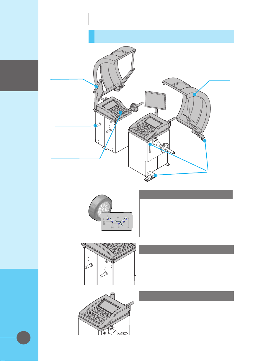
Parts' names
■Monitor
■Work Table
■Control Panel
■Adaptor and
Accessories
Support
■Main S/W
Introduction
Introduction
4
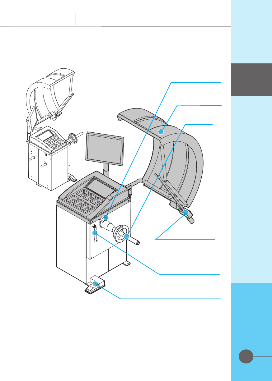
■Wheel Guard
(option)
■Laser Pointer
(option)
■Shaft
■Automatic Gauge Arm
■Automatic Width
Gauge(option)
■Electrical Input Switch
(break pedal-option)
Introduction
5
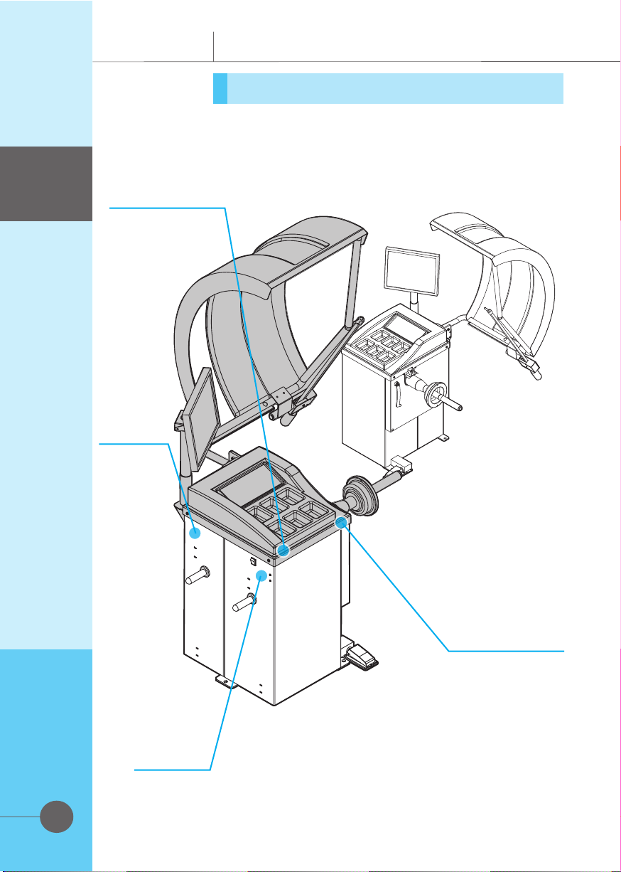
Positions of name plate and labels
Introduction
Introduction
■Product
Identification
plate
■Operator's
Manual Ref-
erence Mark
■Warning Sign
■Warning Sign(Cover)
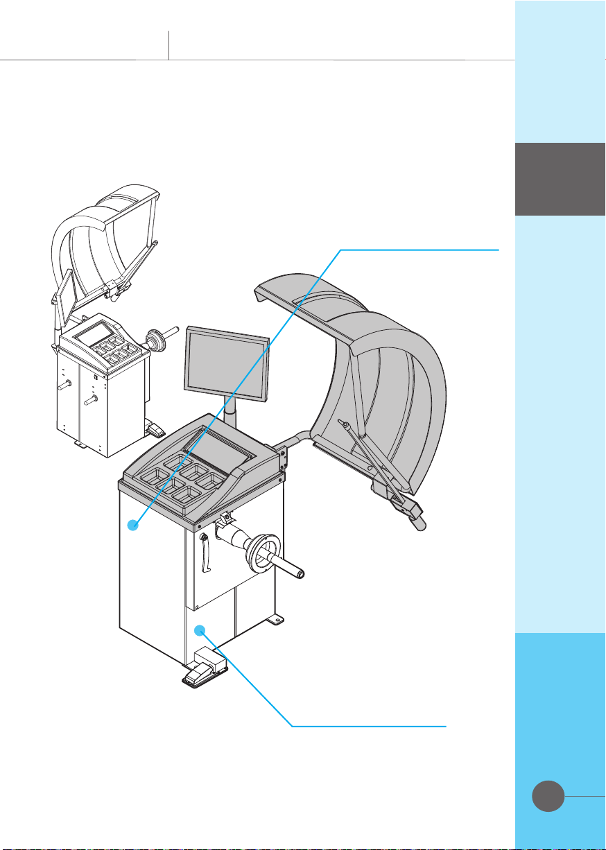
6
■Warning Sign(Feet)
■Heshbon Logo
Introduction
Introduction
■Warning Sign
7
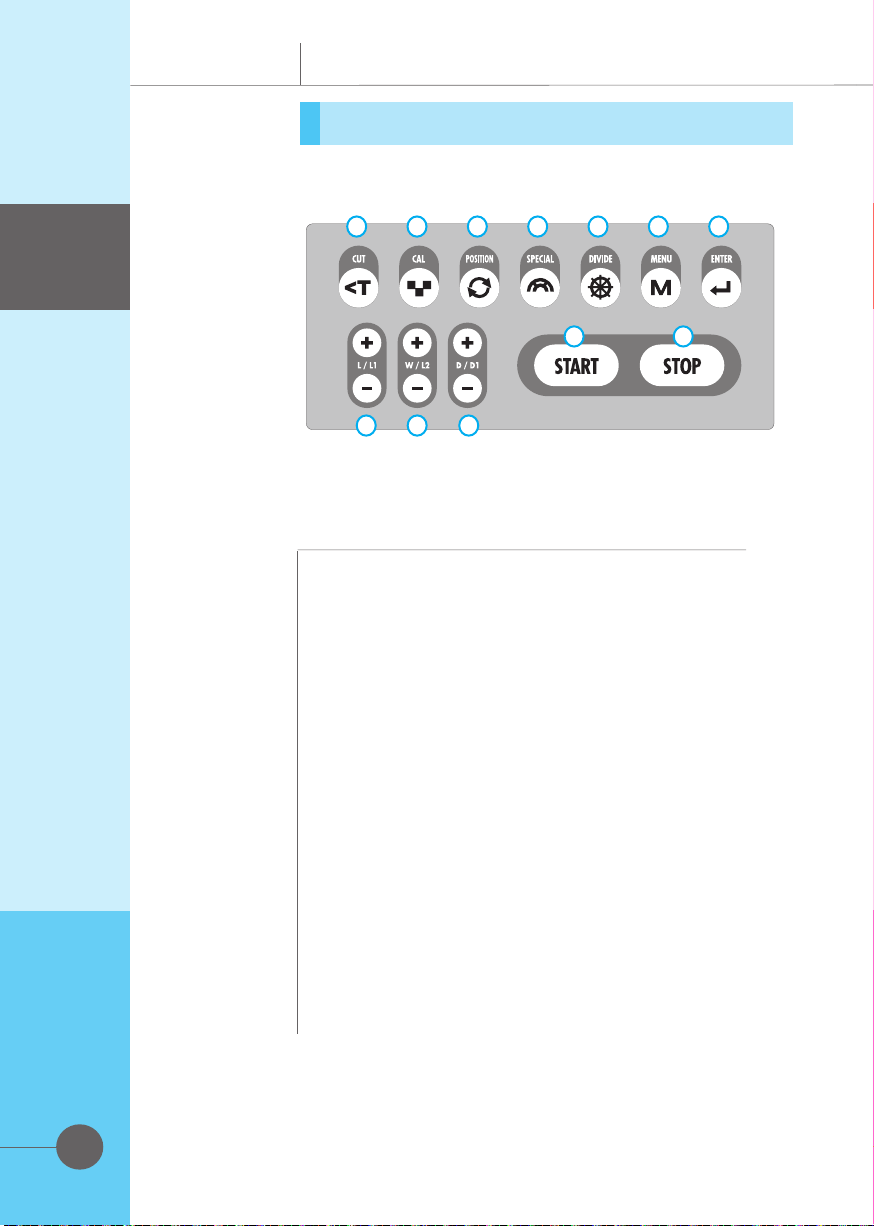
Functions of Control Panel
■ Functions
①Cut -
Button used to check the left weight amount
②Cal -
Press if to run Self-Calibration
③Position -
Automatically stop on an unbalanced position of
the wheel measured(optional)
④Special -
Measure a special aluminum wheel
⑤Divide -
Split function.
⑥Menu -
Press if to run Self-Calibration
⑦Enter -
Enter/exit button
⑧L -
Rim distance setting buttons
⑨W -
Rim width setting buttons
⑩D -
Rim diameter setting buttons
⑪Start -
Button used to start measuring
⑫Stop -
Emergency stop button
■ Name
Introduction
Introduction
1 2 3 4 5 7
810
9
6
11 12
①Cut ②Cal ③Position ④Special ⑤Divide ⑥Menu
⑦Enter ⑧L ⑨W ⑩D ⑪Start ⑫Stop
8
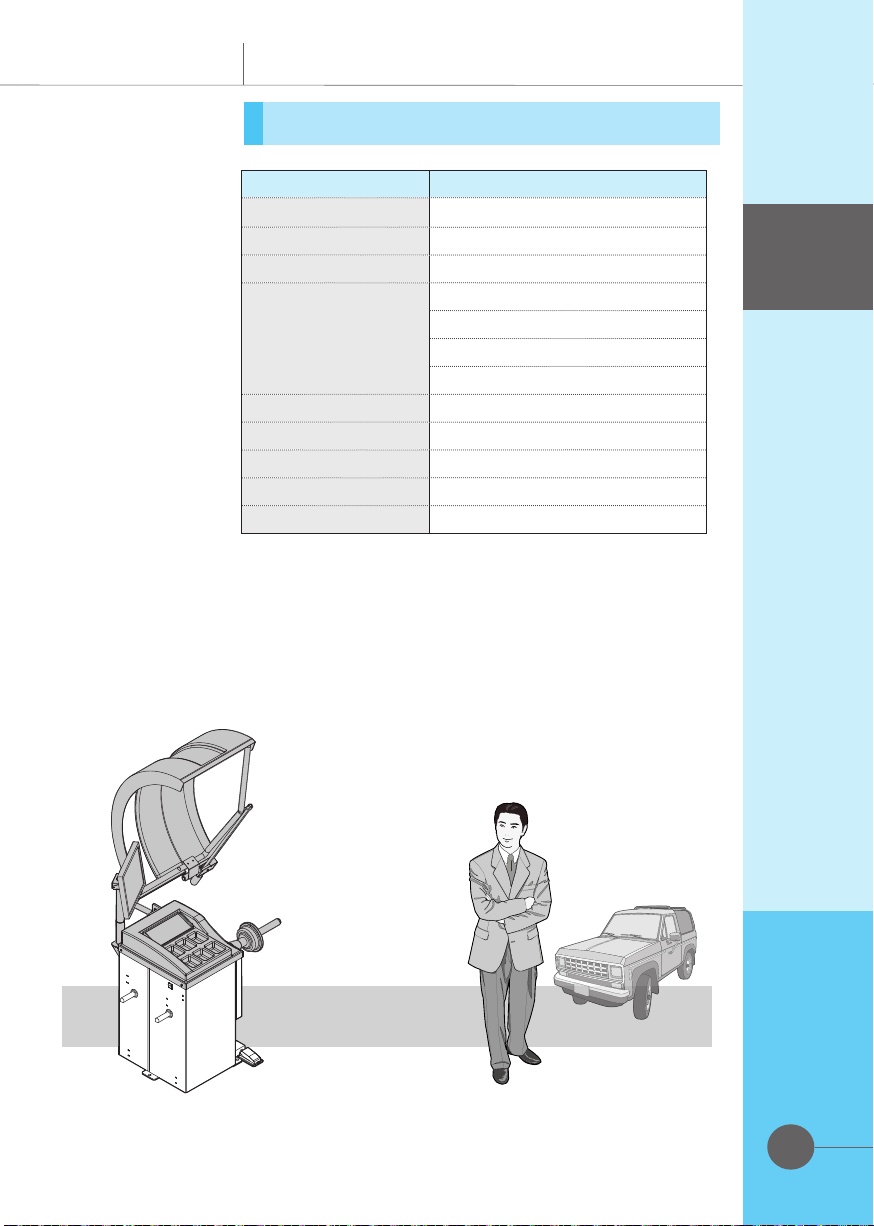
Specification
Model HW-105
Measuring method Both sides(In/Out) at the same time
Measuring unit 1g (both sides)
Measuring time 7 ~ 12sec
Measuring range
Distance 0~18cm
Rim Width 1.5"~20"
Rim diameter 10" ~24"
Weight 65kg
Balancing speed Approx 200rpm
Display LCD Monitor
Rated voltage AC220V(60Hz/50Hz)
Weight 90kg
Nut type One-touch type
Enjoy repairing
Your source of excellent equipment
Introduction
Introduction

Illustrations throughout
this manual
About illustrations
used in this manual
It will help you under-
stand this manual and
please read it carefully.
The rules are limited to
this manual.
9
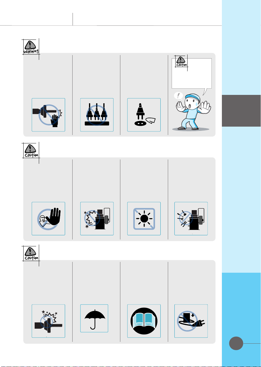
Danger/Warning/Caution
A user may be injured or even dead unless
the directions are kept.
Not keeping the directions may result in
serious injuries or damages on properties.
Not keeping the directions may result in
injuries or damages on properties.
Terms and descriptions to improve your
understanding
Tips for your efficient use
See the related pages
Do not attempt to
operate this product
unless you are skilled
to do it.
(Operating incorrect
buttons may cause
problems in this
product)
Work only on an
even place for
safety purpose.
Do not install this
product on a place
exposed to rain or
water.
(this product is
indoor use only)
Do not apply
excessive force
to unplug power
cord.
▶ It may case an
electric shock or
a fire.
Do not expose this
product directly to
rain and moisture.
▶It may cause an
injuries or even
death
Do not work with
this product close
to heating source.
▶It may cause an
injuries or even
death.
Do not touch
power cord with
wet hands.
▶ It may cause
injuries or even
death.
Do not use dam-
aged power plug
or loosened outlet.
▶ It may cause
injuries or even
death
Safety
Safety
Cautions
10
Be cautious that
fingers may be
hurt by the rotating
shaft.
▶ It may cause
serious injuries.
Do not insert
multiple plugs on
an outlet.
▶ It may cause an
electric shock or
a fire.
Make sure that
electric contacts/
pins should be
maintained clean.
▶ It may cause an
electric shock or
a fire.
Read this manual
carefully before
use.
Do not attempt to
push any incorrect
button while it is
working.
▶ It may cause un-
expected malfunc-
tion.
Do not apply any im-
pact on the balance
body frame[housing]
or expose it to dust.
▶It may cause unex-
pected malfunction.
Do not expose this
product to direct
sunrays.
▶ It may cause
unexpected mal-
function.
Do not modify the
control panel and
structure volun-
tarily.
▶ It may cause
unexpected mal-
function.
Do not apply any
impact on it nor
expose it to dust
or moisture.
Make sure to in-
stall it indoors only
and protect it from
rain or snow.
Read this manual
carefully before use.
▶ Serious accidents
may happen unless
the danger/warning
information is kept.
Do not bend the
power cord or
place any heavy
article on it, prob-
ably cutting it off.
Safety
Cautions
Safety
11
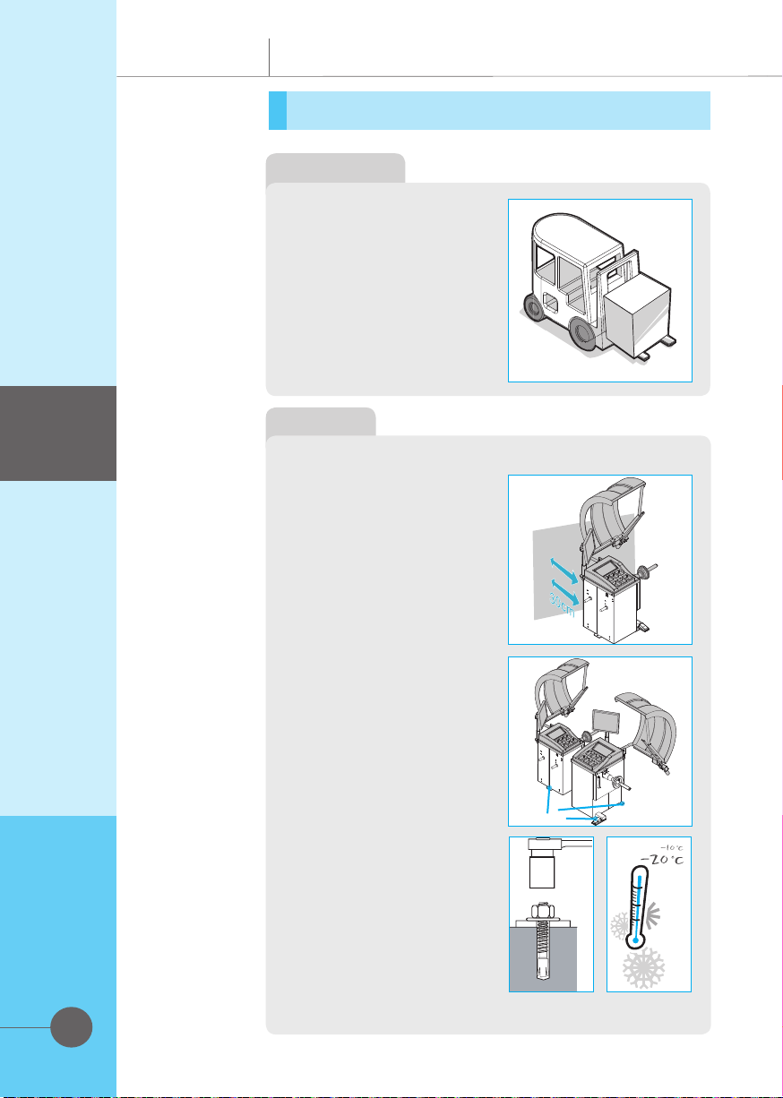
Transportation and installation
Anchor bolt
Installation
Installation
Transportation
▶Upon arrival at an installa-
tion place, move this package
to an installation location using
a forklift or truck.
▶Unpack and check the com-
ponents in the package. If any
missing component is found,
immediately contact your deal-
er or the company.
Installation
▶LOCATION
The wheel balancer must be
located on a solid floor in
concrete or similar material.
An underlying cavity could
cause imprecise imbalance
readings.
▶SAFE DISTANCE:
For the safe and ergonomic
use of the machine it is advis-
able to locate it a minimum of
300 mm from the surrounding
walls.
▶FIXING INSTRUCTIONS:
The machine base has 3 holes
for fixing to the floor with an-
chor bolt. This is essential to
ensure accurate and consist-
ent readings.
Check that the supply voltage
is the same as that indicated
on the machine identification
plate(220V±10%, 50/60㎐)
▶Connect the electrical power
plug to an outlet that con-
forms with European stand-
ards or the standards of the
country in which the machine
is used.
The plug must have a ground/
earth connection.

12
Transportation and installation
Installation
Installation
▶Check the effectiveness of the
ground/earth connection.
▶The machine must be connected to
the supply through a multi-pole cut-off
switch in conformity with European
standards and with contact opening
gap of at least 3 mm.
▶When connected and switched on,
mounted wheels must rotate in a
clockwise direction as seen from the
right-hand side of the machine. The
correct direction of rotation is indi-
cated with an arrow on the machine
body.
▶If the machine functions abnormally
immediately switch off the main
switch and check the troubleshooting
section of the Instructions
Manual.
Installation
This product is limited to in-
door use only. Therefore, do
not install it at a place ex-
posed to rain, snow or dust.
In case it should be inevitably
installed at an improper place,
it is necessary to manage
this product thoroughly at all
times for performance main-
tenance. To store this prod-
uct for a long time, turn it off
first and cover it with packing
material.

13
Modes according to Wheel Types
From the measurement screen, press button ALU to
select the type required. The 5-LED displays show the
position where to apply the weights. If a spin has al-
ready been performed, the processor automatically re-
calculates, for each change of mode, the amounts os
unbalance according to the new calculation.
Application
Application
Lead attach-
ment location
Wheel's cross
section
Balancing of steel or light alloy rims with
application of clip-on weights on the rim
edges.
■DYNAMIC
The static mode is necessary for
motorcycle wheels or when it is not
possible to place the counterweights on
both sides of the rim.
■STATIC
Balancing of light alloy rims with
application of adhesive weights on the
rim shoulders
■ALU1
Balancing of light alloy rims with hidden
application of the outer adhesive weights.
■ALU2
■ALU3
Combined application: clip-on weight
inside and hidden adhesive weight on
outside.
■ALU4
Combined application: adhesive weight
inside and clip-on weight outside.

14
1
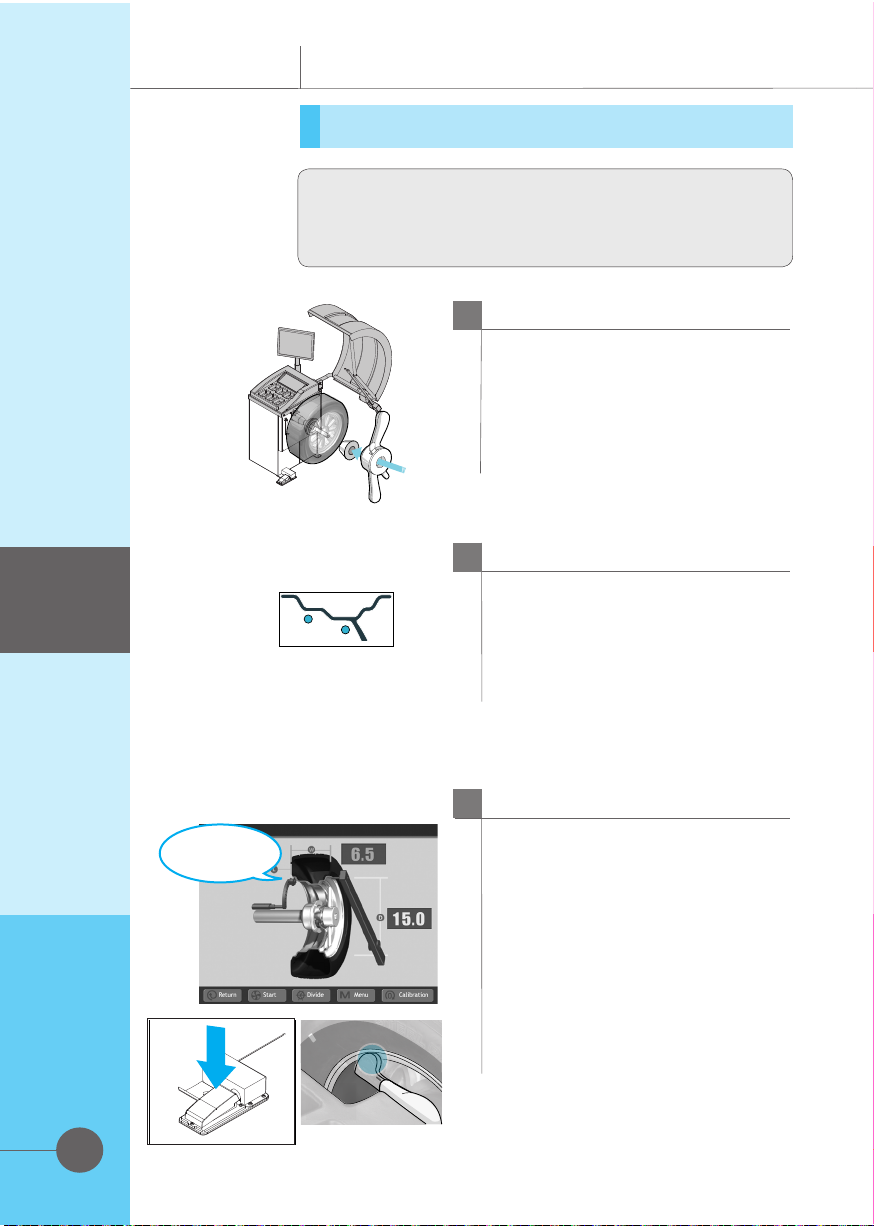
Switch on the machine with the main switch.
Power supply
2
Mount the wheel on the machine, centering it
on the relevant cone or adaptor and tighten
it carefully with the quick-nut.
Tire wheel placement
Application
Application
DYNAMIC
▶applicable to general wheels
Measuring
them at the
same time.
(option)
3
3.1 Automatic rim Distance (offset) and Diameter -
Move the automatic gauge arm to the inside edge of
the rim, touch the pointer to the rim edge, touch the
tip of the width arm to the outside rim edge where
weights will be placed as illustrated in left Figure.
Press the pedal. Then the beeper will sound when the
parameter values are calculated and entered auto-
matically. Return the arms to its home rest position
on the balancer. Do not allow the measurement arms
to “dangle”.
3.2 Manual Parameter Entry-In the event of auto-
matic gauge failure, ANY parameter value can be in-
put manually.
3.2.1 Manual Distance Entry - Move the distance
gauge arm to touch the inner edge of the wheel where
weights are to be placed and observe the reading on
the scale of the distance gauge. Press manual Wheel
Parameter button followed by pressing the + or -
button(L) until value is displayed in the left display
window.
3.2.2 Measure Rim Width Manually using rim width
calipers. Measure wheel where corrective clip-on
weight would be applied. Enter the measured width
by pressing the Parameter button followed by the +
or - button(W) until the desired value appears in the
right display.
3.2.3 Manual Rim Diameter Entry-Read the rim di-
ameter marked on the sidewall of the tire <picture A>.
Enter the measured rim diameter by pressing the Pa-
rameter button followed by the + or - button(D) until
the desired value appears in the right display.
NOTE: For a more precise balancing of performance
wheels, an “ALU-S” Mode is available for
precision determination of wheel parameters. This
feature allows exacting placement of corrective
weights as well. See Page for detailed instructions.
NOTE: The parameter arms must be in the Home
rest position when the balancer is powered up.
This establishes the arm starting position.
Enter rim parameters
<Picture A>

Tire rotation
Correct
balancing
position
Weight
attachment
15
DYNAMIC ▶CORRECTION OF THE UNBALANCE
5
Spin the wheel by lowering the wheel
guard or by pressing the Start but-
ton. When the balancing cycle is
completed the wheel will stop auto-
matically and the unbalance values
will appear on the monitor.
Closing Wheel guard
6
Read the unbalance value on the
outer display. Values are displayed in
grams but can be displayed in ounc-
es if required and are automatically
rounded to the nearest commercial
wheel weight.
Unbalance values
7
Raise the wheel guard and turn the
wheel until the displays of the outer
plane unbalance position arrow is il-
luminated red in the screen. A tone
will sound indicating top dead cent-
er. Apply the wheel weight at twelve
o’clock position. Use the foot op-
erated shaft lock to prevent shaft
rotation while placing weights.
Correcting OUTER values.
Before spinning the wheel make
sure proper eye protection is worn
by all personnel in the vicinity of
the balancer.
Application
Application

16
8
Correct the inner plane in the same
manner.
Correcting INNER values
9
Lower the wheel guard to spin the wheel
again and check that the readout is
“00” “00”(OK message will appear
in the screen). If a residual imbalance is
displayed:
A. Check the rim parameters, if entered
value is incorrect, correct as needed.
Imbalance values will be recomputed
after re-spinning wheel.
B. Check if the balancing mode selected
is the most appropriate. If not, choose
the right mode and re-spin.
C. The wheel weight could have been
placed at a wrong position. To check
this, position the wheel at the correction
position for the outer plane.
If the wheel weight previously attached
is in sector ‘L’ or ‘R’ <Picture B>,
move the wheel weight up about 1”
(2.54cm).
If the wheel weight is in sector ‘D’
cut a piece of the wheel weight of an
approximate value corresponding to
the value shown on the right display, or
replace the wheel weight with a lighter
one. If the wheel weight is in sector
‘U’ add a weight of value indicated by
the display or replace the wheel weight
with a heavier one. Repeat the same
operation for the inner plane.
NOTE: If this situation is repeated, your
machine may be out of calibration and a
calibration operation might be required
as instructed on page __ .
D. If an ALU function was selected
ensure that the wheel weights have been
placed in accordance to the program
chosen.
E. Check that the quick nut is tight and
that the wheel is not slipping against the
backing collar.
F. Check that the wheel and adaptors
are clean.
Verification of the results
Application
Application
If vibration is still present after balancing,
check the following possible sources of
vibration:
1. Stones caught in the tire tread.
2. Tire slippage on the wheel.
3. Incorrectly mounted wheel.
4. Imbalanced wheel covers.
5. Excessive radial or lateral runout in the
tire or wheel.
6. Damaged wheel bolt holes.
7. Worn universal joints.
8. Imbalanced brake rotors or drums.
9. Worn or damaged balancer ccessories.
<Picture B>
17
ALU -S Special ALU function
1
Switch on the machine with the
main power.
Follow the procedures below
2
Press the ALU button three times to
activate the Special ALU mode(ALU
2 mode), the display will read “ALU
L - 2” when activated.
Mode change - ALU2
This is a mode similar to ALU mode 2. The difference
is that the distance and width parameters are accurately
defined for a more exacting weight placement,
3
Extend the automatic gauge arm
and touch the position of the left
weight position, then press the
brake pedal.
The high tone will sound when
dimension is entered. Return the
gauge arm to the rest position.
The width arm is not used in this
procedure.
Measuring ALU L-1 values
Application
Application
ALU-S mode display
left weight
position
Table of contents
Popular Wheel Balancer manuals by other brands


Hofmann
Hofmann geodyna 7340 Operation manual

HENNESSY INDUSTRIES
HENNESSY INDUSTRIES Coats 885 Safety Instructions, Set Up Instructions, Operation Instructions, Maintenance Instructions

Hunter
Hunter GSP9712 Operation instructions

Weaver
Weaver W-957-40 Operation manual

Sun Microsystems
Sun Microsystems SWB 300 Operator's manual

ATH-Heinl
ATH-Heinl W62 operating instructions


