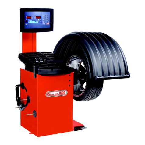
BRIGHT CB460 Series User manual

- 1 -
WHEEL BALANCER
MODEL
:
CB460

- 2 -
This instruction manual has been prepared especially for you.
The manner in which you care for and maintain your banlancer
will have a direct effect on its overall performance and longevity.
READ THIS ENTIRE MANUAL
BEFORE OPERATION BEGINS.
RECORD HERE THE FOLLOWING INFORMATION
WHICH IS LOCATED ON THE SERIAL NUMBER DATA PLATE
SERIAL No.:
MODEL No.:
MANUFACTURING DATE:
Warranty Item
The machine include the operation system, tooling and accessories will be under warranty for one
year.Afer the confirmation of eliminate improper damage and unreasonable use. During this time,
the manufacturer will repair or change the return parts or machine from the customers. The charge
will be paid by the manufacturer. But the manufacturer will not have the responsibility for the
normal wear and tear, improper use or transport, or lack of maintenance. The manufacturer will
not inform the customer when the products improved or production line rebuild, the difference rise
from this is not include in this warranty. All the change of this warranty item will be according to
the machine’s model and serial number, all the complain must be provide the machine’s model and
serial number.

- 3 -
INDEX
1. The brief description of wheel balancer
1) Working scope
2)Instructions for the stickers (include the warning sticker)
3)Appearance of wheel balancer
4)Performance and feature
5)TechnicalData
2. The use of wheel balancer
1) Precaution in transport the machine
2)Demand for install the electrical device
3)Air supply connection
4)Precaution in installation and operation
5)Call your attention to the followingproblems
6)The Brief Controlling Panel
3. The Brief Description Controlling Panel
4.Basic operation of balance detector and selection of functions
5.Self-calibration
6.Selectionoffunctions
4. Code in computer self-diagnosis
5. Wheel Shaft Counter positioning
6. Standard accessories of Tire Balance Detector
7. Code in Computer Self-diagnosis
8. Wheel Shaft Counter positioning
9. Standard accessories of Tire Balance Detector
10.Trouble shooting
11.Presettingthestored3itemsdata
12. Use for grease
12.1 Grease the balancer
12.2 Safety data list for use of grease for balancer
13.TheDrawingOfPowerBoard

- 4 -
14.TheDrawingOfComputerBoard
15.Electrical diagram
16.Spare part list
1. THE BRIEF OF WHEEL BALANCER
1)Working scope
This microcomputer control, digital display, high-performance
balancer can balance car tyre, small passenger car tyre and light
truck tyre, also it designed for balancing super truck and
passenger car tyre, that up to 105kg. also it can balance special
shape tyre for aluminum alloy tyre.
2)Instructions for the stickers (include the warning sticker)
Ⅰ、Nameplate
The nameplate place on the back of the machine, on the upright side of the machine body,
the meaning for every part is as below:
A、CB460
model
B、Serial number
The first three figure is the model, the fourth to seventh figure is for manufacture date,
and the last four figure is for serial number for the machine
Ⅱ、Lightning mark
This sticker place on the back of the machine, show where to put in the
Power wire and call the attention for the safety for the user.
Ⅲ、Warning for the rotating part of the machine
this sticker place near the balancing shaft, to remind the user that this part
is the rotate part, belong to the dangerous part, not touch it by hand, the
arrow also show the direction for the rotating.
Ⅳ、Ground mark
this sticker place on the left side of the back of the machine, to show where
to connect the ground wire.

- 5 -
Ⅵ、、The original data
this mark is under the nameplate on the back of the machine body,
or on the front or left side for the inside machine body. (some
machine only put them inside the body). These three data is input
before the delivery after the calibration (save in the CMOS chip ),
that is for the reference for the user later.
3)Appearance of wheel balancer
4) Performance and feather
*The machine adapt the center computer system of import parts, high intelligence, high
duration.
*Main shaft use importing bearing, low noise, high precision.
*Advanced computer driving system.
*Automatic calibration function of static and dynamic.
*Three ALU program.
*Self calibration and Self-diagnosis
5)Technical Data
NO Item Technical data Note
1 Kind for rim Alu, steel and alloy rim

- 6 -
2 Balancing class
car、light truck、Super truck and passenger
tyre
3 Balancing mode Dynamic, static, and three ALU
4 Driven style Driven by electrical
5 Power supply demand 230V 50Hz
6 Style for put the weight Standard
Suit for different
style
7
Measure for inside and
outside
Standard Suit for every model
8
The machine start when
low down the cover
Semi-automatic
low down the
cover,and press
the START button
9 Quick handle nut Standard
10 Caliper/weight/handle Standard
11
Change for millimeter and
inch
Standard
12
Change for gram and
ounce
Standard
13 Calibration Standard
14
Self- diagnose /show
Err-
Standard
15 Wheel lifter Used for truck tyre
Car balancer not
use this
16 Brake Automatic/Manual
17 Brake Automatic/Manual Brake
18 Display cover Packed separately
19 Display panel LBD
20 Distance setting Manual
21 Cone 5
22 Balancing time 7s(16″standard rim)
Relative to wheel
weight
23 Max. balancing speed 230r/min
Relative to wheel
weight
24 Balancing precision ≤3g
25 Max.wheel width 20″

- 7 -
26 Max.wheel diameter 47″
27 Max.rim diameter 10″~24″
28 Max.rim width 1.5″~20″
29 Max.wheel weight 150kg
30 Dimension(after packing)1320X950X1180(LXWXH)
31 Machine weight 274kg Include wheel lifter
32 Temperature 0~40℃
33 Hmidity ≤75%
34 Noise ≤70dB
35 Resistance ≥20MΩ
36 Power About 800W
2. The use of wheel balancer
1) Precaution in transport the machine
A、Be careful when transport and unpack the machine, to avoid the damage of the machine.
B、Check if the machine is damage or not during the transport, and make the record for the
problem, then show them to the carrier, and make the record on the document.
C、Check the structure for the machine, to see if the data on the machine’s nameplate and
motor’s nameplate is the same as demand, if have doubt,
Reflect it quick, so that can make the resolution for this in time.
D、All the work about electricity and adjustment must be operated by the authorized person.
2)Demand for install the electrical device
A、 Demand for the electrical wire. Before the install, make sure the power supply is the
same as the machine demand,the wire of the machine can not connect with the
power supply directly, a breaker should be used, to avoid the damage of the machine
when the power is not stable, normally, a 15A breaker (with overload protect and less
load cut off) is recommended, if a bigger breaker is used, the fuse should be installed,
the lead wire area
can not less than 1.5mm2
(earth wire can 1.0mm2),oil-against cable can be used, (built on
stilts or insert into hose),or monolayer insulate wire can be used through wire groove or

- 8 -
pipeline. If the working site is not good, much equipment, vehicle and people go through,
the wire should be built on stilts or cover up.
B、Demand for the power supply. The voltage should be stable, the wire should have overload
ability,fluctuate of the voltage should not exceed the rated voltage 10%,fluctuate of the
frequency should not exceed 1Hz,or the regulator should be mounted, to keep the voltage
and frequency stable.
C、Demand for the socket. The car balancer is equipped with the wire and plug before delivery,
the operator can only choose the socket according to the plug, but the socket must apply for
the following demand:
the rated capacity should more than 500VAⅠ,rated current more than 15A;
the socket must have reliable earth wire, the socket with only two clamp can not beⅡ
used,or it will affect the precision of the balancer and ability of anti-jamming.
Ⅲit better with the switch,if there is something wrong with the wire, can cut off the
electricity or it will damage the machine
ⅣThe plug should connect well with the socket.
ⅤIt is better use the special socket, do not use many equipment on the same socket.
3)Air connection
A、Wheel lifter technical data:
Working range:0.1~0.8MPa(0.5~0.8Mpa in normal working )
Precision:0.01MPa
Air supply:this machine is not equipped air supply, the customer need to equip the air
supply themselves, it should be control within0.6~0.9Mpa, then adjust to below 0.8Mpa
by the valve on the lifter, the air supply should have filter, the precision should 5μm ;
medium flux >0.15m3/min, temperate 5~60 . The lifter equipped with quick union, Φ8℃

- 9 -
(inside) hose should be used to connect with the air supply, then tighten it by caliper.
Working condition: according to the demand for the balancer
Net weight:50Kg
Dimension:1129×1190×728mm (LXWXH)
B、Unit conversion
1Mpa=l0Bar
1Bar=14.5Psi
1Bar≈1Kg/cm2
B、Pneumatic
diagram(right)
4)Precaution in
installation and operation
*Don't place the detector in an extreme hot or cold condition, and avoid setting the
machine close to the heating radiator, tap, air humidifier and stoves.
*Don't place the detector near the window under the direct sunshine .In case of inevitable,
the window curtain, shield and hood should be used to shade the detector.
*No contact of the machine is allowed with dust, ammonium, alcohol, diluents and
pulverized adhesive, etc.
*The detector should be installed on a leveled ground.
*Never place it close to the air compressor or any substance that may generate vibration.
*During the operation don't close to the detector unless the operator.
*The dynamic balance detector should use separated power(230V) socket. Don’t connect
any other wire in this socket. Attention must be paid to the reliable grounding, if there is
no grounding connection in the socket, it must be added before connect with the power

- 10 -
source.
*The wire line of dynamic balance detector should be prevented from stepping on.
*Contact with the special service man for maintenance before you have to move the
dynamic balance detector.
** At least 80cm should be left at the back of the machine, 50 cm on the left side of the
machine should be left, to ensure the aeration ,disperse and the normal work, 200 cm on
the right side of the machine should be left, to facility the mount and demount the tyre or
mounting the lifting device.
*The lifting device should be used when the tyre is more than 15kg, not use hand to lift
tyre directly, to avoid the injury of the operator.
* Fix the machine on the ground by bolt before operate the machine, (fix three points),or
the result may not correct due to the shake of the machine, especially when the tyre
more than 35kgs.
*The machine equipped with the protection cover and the switch, the motor automatically
start when the cover low down, and will stop when lift up the cover, in order to ensure
your safety, do not demount the cover.
*The operator should wear the clothes –fitting, tighten the button, wear the thin gloves,
the thick gloves will affect the operation, do not wear sandal, it is better to wear insulated
shoes.
* Around the balancer, there should be no other electrical equipment, or the machine
≥50cm
≥80cm
≥200cm

- 11 -
with big power, to avoid the electromagnetism interrupt the testing precision.
*If the ray not good for the working site, the lighting device should be prepared, it is better
to use daylight lamp or incandescence clamp, brightness should fit for the working.
5)Call your attention to the following problems
*Never dismount or refit the dynamic balance detector by yourself.
*The part of rotational shaft should be prevented from any strike.
*The dynamic balance detector can be restarted only 5 seconds later after shut down.
*On the top of dynamic balance detector never put many heavy substances.
*Please refer the content of self-calibration in case of abnormal operation .Cut off the
power supply and pull out the plug immediately, if the noise, smoke or any other
accidents take place suddenly, then inform the relevant service man.
*In front of the power socket of the dynamic balance detector, space must be left so that
you can rapidly pull out the plug.
*The dynamic balance detector can’t be used beyond the scope of its functions stipulated
in the manual.
3.The Brief Description Controlling Panel
A、Panel instruction
a.b.Value display indicator.

- 12 -
c.d.Positioning lamp for unbalance point.
When the indicator lighting, the machine in the
position work for big tyre.
When the indicator lighting, the machine in the
position work for small tyre.
。
g. Balancing block mode
indicatinglamp.
B、Instruction for the button
h. Width setting button. Press down or
to adjust the set width value on indicator

- 13 -
i.Distance setting button. Press down or
to adjust the set distance value on indicator
j.Diasettingbutton.Pressdown or
to adjust the set Dia value on indicator
p.High precision balance button. Indicator display’’00’’when
unbalance<5g, press down this button to show the left unbalance
value.
o.Button for static balance and selecting the position & mode of ALU
balancing block.
m.Button for automatically test the inputting value.
k. Button for emergency shut down.
l.Starting button.
n. Conversionbuttonforbigorsmalltyre
4.Basic operation of balance detector and selection of functions
4.1 Basic operation of balance detector
4.1.1 Turn on the power switch on the left side of the detector, indicator
a displays "001", and then the indicators a,b change to"-A-","8.0"

- 14 -
4.1.2 Lifting the tyre
The lifter should be used to lift the tyre, when the tyre more than 15kg. Roll the tyre to the lifter (the
tyre edge should be 10 cm from the shaft edge, avoid the damage to the shaft during the operation).
Hold the tyre one hand, the other hand adjust the valve, ( turn clockwise the lifter is lifting, turn anti-
clockwise the lifter is down,) check the center position of the tyre, when the tyre center match to the
shaft, stop the valve in the center position, push the handle to make the tyre in the shaft, not damage
the shaft.
Note: after testing, demount the tyre, low the lifter to the lowest point, stop the valve in the
center position
4.1.3 Mounting of tyre
Select the positioning cone that fits the central hole of the rim, to install it at the
center of rotational shaft, then tighten and lock it with the handle nut.
(The maximum weight of wheel should not more than150kg.)
4.1.4 Input the value “A”
Pull the distance gauge A to the position, where the balance block is to be set. Press
the or button near “a” and input the reading on the gauge into indicator b,
meanwhilethe indicator a should display the value as “A”.
4.1.5 Input the value” L”
Use the width gauge that taken from the accessories to measure the width between
two sides of the rim, press or button near “L” to input the reading on the
gauge into the indicator b, mean while the indicator a should display the value as “L”.
4.1.6 Input the value “D”
After the value of Dia. confirmed, press or button near “d” to input the value
into the indicator b, meanwhile the indicator a should display the value as “D”.
4.1.7 Pull down the protection cover,press the button to start the operation; several
seconds later, the detector will automatically stop.
4.1.8 After stopping.,the value of unbalance for internal and external displayed by indicators a and
b .Rotate the wheel by hand, the positioning lamps c,d will constantly flash , c indicate the internal

- 15 -
unbalance value, d indicate the external unbalance value.
4.1.8 Run wheel till all lamps in a set of c or d start to light, it means that the
position of rim’s highest point is the unbalance point. Among which the d
represents the value of internal side of rim and the c represents the value of
external side of rim
4.1.9.At the unbalance point of the rim, mount a balance block corresponding
to the measured value, the indicator a represents internal side of the rim,
while the indicator b represents the external side of the rim.
4.1.10 Repeat the procedure 6-10 till the indicators a and b show “00”.
4.1.11 Dismount the tire from the rotational shaft, the balance detection is
now finished.
4.2 Several unit conversion
(1) “inch” and “mm” conversion
“inch” and “mm” conversion in the rim “L” . In “L” display, the unit of display is “inch”, if you want to use
“mm”, you can converse them. Converse method: first press “STOP” button for long time ,at same
time press “+” button or “-” button near “L” you can get it.
“inch” and “mm” conversion for rim width after conversion, the display unit is “mm”
(2) “inch” and “mm” conversion for rim diameter.
The display unit is “inch” in normal condition. When use “mm”, you can converse from “inch” to “mm”.
The conversion method: first press “STOP” button for long time ,at same time press“+” button or “-”
button near “d”, you can use “mm” unit.
Turn off the machine, and “START” the machine again, The unit for rim width diameter is inch.
(3) “gram” and “ounce” conversion
The display unbalancing value’s unit is gram, when use “ounce”, you can converse from “gram” to
“ounce”.
The conversion method: first press “STOP” button for long time,at same time press“+” button and “-”
button near “a”, you can use “ounce” unit. Turn off the machine, the machine will remember the unit, if
you want recover the “gram” you can repeat the about operation.
5.Self-calibration
When there is doubt in the precision of the measured value this function can be used. Don’t shut down
the detector during the operation, because it may cause the inputting of the wrong value. (Don’t
arbitrarily use this function)
Procedures in operation:
1)Mount the balanced tyre.
+

- 16 -
2)Press down the “CAL “ button, don’t loosen, then press the
button. The indicators a and b show “CAL”-“CAL”, the
positioning lamp of unbalance will flash several seconds, and
then went out automatically.
3)Press down the starting button, after several seconds the
detector automatically stop, the indicators a and b show
“Add”-“100”. Add a balance block of 100g at any point of
external side of the rim.
4)Press this button, the wheel will rotate, the indicators a and b
show "End"-"CAL", the calibration is complete.
6 Selection of functions
This lamp lighting shows that it is adapt to the type used for motorcycle, or
those wheels at both sides of which placing the balance block is not allowed.
This lamp lighting shows that it is adapt to the alloy rim, at the shoulder of
which the balance block can be stuck on.
This lamp lighting shows that it is adapt to the alloy rim, on the external
hidden side of which the balance block can be stuck on.
This lamp lighting shows that on the external side of which the balance block
can be stuck on, and at the internal side of the rim, the balance block can be
braced or inserted.

- 17 -
When the four sets of indicators all went out, it shows the standard
balance. (Whenever you start the detector, the computer
automatically set at such state.)
7.Code in Computer Self-diagnosis
Trouble in phase generator or power board, phase board is damaged
or phase connecting line is break.
Rotation speed is too low or wheel hasn't been mounted (with tire).
Too big unbalance, try other wheel
Errors in power system, rotation direction is not right.
Nonsense.
Memory damaged or signal lost, calibrate again or renovate.
The procedure of calibration is not appropriate or computer
board or sensor damaged, sensor connecting line is
damaged, power have no –5v.
8.Wheel Shaft Counter positioning
Counter positionging method is widely used in
the foreign countries. It is applicable to common
steel rims and aluminum alloy rims. Especially
for the new rims of type 2000,and provides high
balance precision.
Procedures of counter positioning:
Place the spring with the
bottom toward the balancer
Place a
suitable cone
Place the
wheel
Plastic cup Quick bolt
cap

- 18 -
9.Standard accessories of Tire Balance Detector
Positioning cone for axis
Locknut
Pin-Accessory
.Standard accessories (List)
*Counterweight nip 1Piece
*Caliper 1Piece
*Positioning cone for axis 5Pieces
*Plumb100g 1Piece
*Spring 1Piece
*Flange 1Piece
*Pin-Accessory 3Piece

- 19 -
10.Trouble shooting
Symptom Cause Solution
No display on the screen after
starting
1.External power malfunction.
2.Power board malfunction
3.Loosen connection between computer
board and power board.
4. Computer plate malfunction.
1.Check the external power supply
1. Replace the power board.
2. Check the plug of the connecting
line.
3. Replace the computer board.
The display is normal,but the
starting switch and the inputing
button heads a,L,d is
malfunction
1.The connection of the switch is not well.
2.Dead computer.
1.Open the cover and tighten the
plug of the touch switch.
2.Start the machine again.
Note
1. The wheel balancer must fixed after taking from the package.
2. Must have earth line.
3. Prohibit to move the main shaft and avoid any crack.
4. Wet proof and shake proof.
5. Advise to use stable power.
11.Presetting the stored 3 items data:
Note: this function can only be used when the balance data is not accurate, even
after the calibration the data still not accurate or stable. When adjust this 3 data,
the 100g weight must be moved away. The calibration must be done after setting
each one of the three datas to make the computer memory the resetting data, or
there will be no effort for this function.Move away the weight tray, and see the
original data marked on the inside of the machine for setting.
The display is normal, but the
brake does not work.
1..Loosen connection between computer
plate and power plate.
2.Power plate malfunction.
3.Computer plate malfunction.
.1.Tighten the connecting
linebetween the computer board
and the power board .
2.Replace the power board .
3. Replace the computer board .
The starting is slow with failure
in braking and imprecision in
balance.
Driving belt is too loose. Adjust the position of the motor or
change the driving belt.
The operation is normal, but the
balance value is not accuracy.
1.The body of machine is placed unstably.
2.Affected by the cone or quick bolt cap.
3.The wheel is not mounted tightly.
4.The power supply inside the machine is
unstable.
4. Power voltage fluctuate violently.
5. .The calibration value changed.
7. The value inside the machine changed.
1.Get rid of the problem, according
to the testing result.
2.Re-tighten the quick bolt cap.
3.Check the power supply.
4.The operator can adjust the
power supply by itself.
5.Replace the computer board if
necessary.
6.Re-calibrate it according to the
User’s Manual.
7.Input the data of dis,In-I,SFA
again,according to the marks on the
machine,then calibrate it again to
check if the machine work
normally.

- 20 -
1) Adjust the SFA data: After the calibration, if the 100g weight is not directly under the wheel
spindle (six o’clock position) or the data is not correct, this function can be used to know the offset
degree of the weight. Move this weight, and press the and buttons, nine seconds
later the indicators will stop flashing, press button of“a”value, then press the button of the
“a ”value quickly,when all the indicators went out, press the button, the left screen display
“dis”,the right screen display the readings,it is not necessary to pay attention to this, press again
the button of the“a”value,( at this time the button represents going into the next
program)the “In-l” on left will display,the right screen display the reading, then press the
button of the “a”value, it will go the SFA window,the right screen display the reading of the
position where the 100g weight located. If it need to change the reading, press the or
buttons of the “L” value to adjust the offset degree of the100g weight, then press the of the
“a”value to exit,do the calibration again, sometimes it is necessary to adjust the SFA reading
again and again, till the 100 weight directly under the wheel spindle
.
2) Adjust “dis” reading:this function used for solving the problem of inside unbalancing value.
Balance the wheel and place 100g weight on the outside of the tire, the reading on the screen will
display in the range of 104-96, take the 100g weight and place it on the inside of the tire, after stop,
the reading is in the range of 104-96, which means normal. If the reading is not between this, the
operator should adjust the “dis” value,the method for finding the “dis” reading is the same as the
way for finding the SFA reading.(adjust the and buttons corresponding to“L”buttton),
after the adjustment go back to the original position, then do the self-calibration again.
3) Adjust the In-1 reading:this function can solve the problem of the divided reading ( inside and
outside). If place a 100g weight on the inside of the tire, the inside screen display 90g, the outer
screen display 10, this function can be used, after the self-calibration go into the In-l program of
adjusting the stored reading. The method for finding the In-1 reading is the same as the way for
finding the SFA reading, according to the inside reading to increase or reduce the In-1 reading
(adjust the and buttons corresponding to“L”buttton),if the reading more than 110g,it
is necessary to reduce this item and exit,then go back to the original position and do the
self-calibration.
12 Use for grease
12.1Grease the balancer
The rotating part for the balancer is only the motor and the balancing shaft, so only the
bearing for these two part need greased, the operator can check the bearing periodically.
If the machine used often (more than two hours one day), the bearing should be check
annually;if the machine not used much, it can check every two year.(the bearing can not
be open for testing, the screwdriver can gore up on the bearing, then hear the sound, to
test it)The bearing is the block out bearing, so the grease not easyto change and out,
also the rotate speed is not high for the machine itself, so it is not necessary to change
the grease. If feel the bearing work abnormal or there is some noise, the bearing can be
Other manuals for CB460 Series
1
Table of contents
Other BRIGHT Wheel Balancer manuals
Popular Wheel Balancer manuals by other brands

Hunter
Hunter SmartWeight Pro Operation manual
Hunter
Hunter SmartWeight Pro Operation manual
Fasep
Fasep RGU 56 XL Use and maintenance instructions

Hofmann
Hofmann geodyna 6800-2 manual
twin busch
twin busch TW 115 Installation, operation and maintenance manual
Hunter
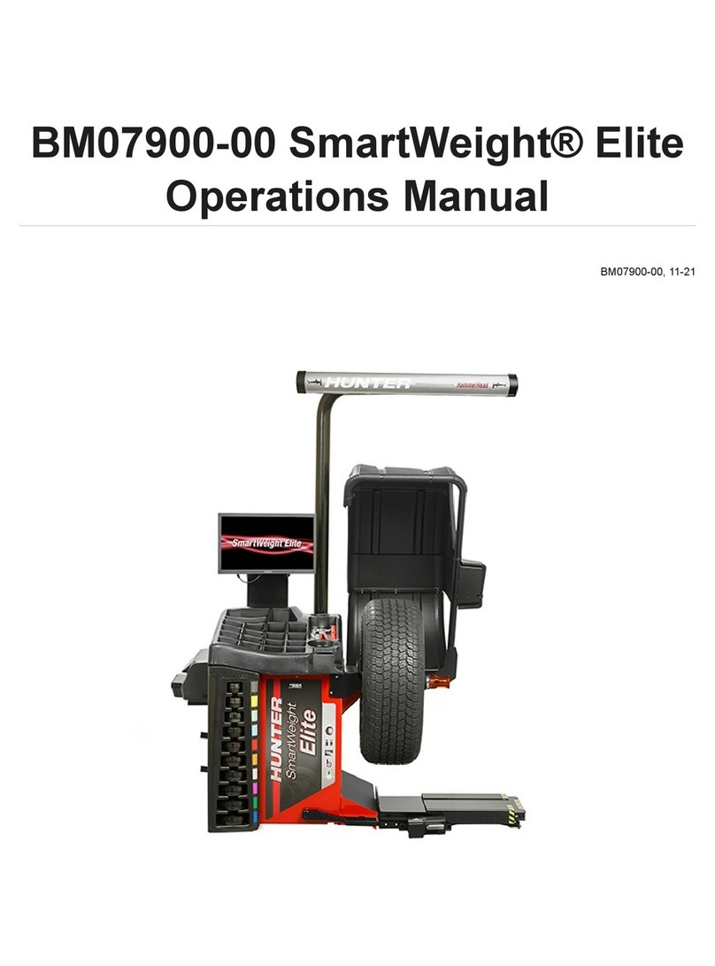
Hunter SmartWeight Elite Operation manual

