Katool KT-B760 User manual

W
WH
HE
EE
EL
L
B
BL
LA
AN
NC
CE
ER
R
- 1 -
1 Performance and characteristics:
- In case of emergency, press the STOP button to stop the wheel from spinning.
- With OPT function, optimize tire rim fit.
- With unit conversion function.
- Multiple balancing methods for your choice.
- Balancing accuracy up to ±1g, short balancing time.
- With self-correction and automatic fault diagnosis function.
- Balance decomposition (hidden lead) function (hide behind spokes)
- With automatic ruler ranging and measuring function

W H E E L B L A N C E R
- 2 -
2Technical Data
The maximum
wheel weight
65kg
Rated power
supply
110V、220V
Balance accuracy
±1g
Width of rim
1.5″-20″
Diameter of rim
8″-30″
3.Control panel:
3.1 Display panel meaning
No. 1-1 window, showing tire inboard unbalance value or reference
distance A size.
Window 2-2, showing tire outside unbalance value or diameter D size.
Window 3-3, showing tire width B dimensions and suggestive
characters.
No. 4-4 window, inner side unbalance position indication (inner side
with key indication).
No. 5-5 window, indication of unbalanced position on the outside
(with key indicator on the outside)

W H E E L B L A N C E R
- 3 -
6- The first five lights on the top row are in balance mode (as shown
in the icon), and the last one is hidden indicator for unbalanced block
segmentation.
The two lights below window 7-1 represent the gram and ounce
switching instructions, and the two lights below window 2 indicate the
tire size unit "mm/INCH" (mm/INCH) switching instructions.
3.2.keyboard

W H E E L B L A N C E R
- 4 -
1. A Manually enter the reference distance size button A, press the
arrow to go up, increase the input size, press the arrow to go down,
reduce the input size.
2. B Manual input size B, press the arrow to go up, the input size
increases, press the arrow to go down, the input size decreases
3, D Manually enter size D, press the arrow to go up, the input size
increases, press the arrow to go down, the input size decreases
4, C correction key/reset key
5, ALU aluminum ring measurement and dynamic balance measurement
selection key
6, D test key, used for balancing machine computer board test
7 OPT balancing machine optimization function operation key, used
for tire rim optimization combination
8. F static and static balance function switch key

W H E E L B L A N C E R
- 5 -
9, The FINE button displays < 5g(0.3oz) actual unbalance value
10, mm/inch for size unit mm/inch switch display
11. Start button
12, STOP emergency STOP and electromagnetic lock button
3. 3 function conversion key combination
3.3.1 After function conversion, shutdown is still saved.
[STOP]+[A ↑]+[A ↓] Grand-ounce conversion key
[STOP]+[C] Start under cover
[STOP]+[FINE] Calibration distance measuring ruler A
[STOP]+[OPT] Calibration Diameter Measurement Ruler D
[F]+[C] Machine System Balance Calibration and Set Machine Parameter
Values
[F]+[START] The machine ages automatically
[D]+[OPT] unbalanced decomposition
Note: Use hand buttons only, do not use clamps or any other sharp
objects.

W H E E L B L A N C E R
- 6 -
4. Tire Balance operation
4.1 After the power is turned on and the device code is displayed, the
display window displays "8.0 5.7 14.0", which proves that the
machine is normal.
4.2 Installation of Wheels
(1) preparation before the test: check and remove the dust, soil and
tread of the tire whether there are metal, stone and other foreign
bodies; Check whether the tire pressure is in line with the specified
value; Check whether the positioning surface and mounting hole of
the rim are deformed, check whether there are foreign bodies in the
tire; Remove the original balance block.
(2) There are three types of wheel installation, including positive
positioning, reverse positioning and additional flanges for large and
medium tires. A positioning method can be selected arbitrarily
according to the actual situation.
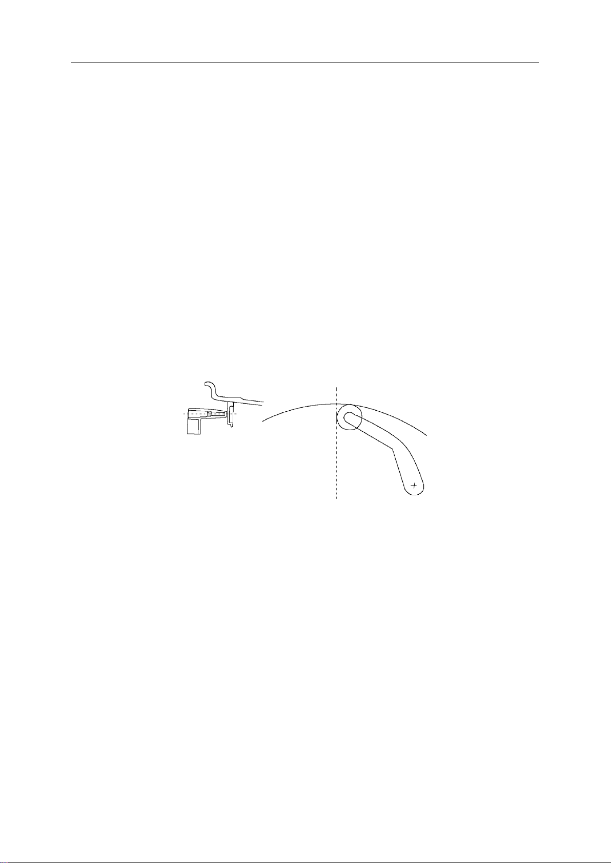
4.2.1 forward positioning
Spindle - Wheels (rim mounting face
inwards)- Fit cone (small head
inwards)- Wheels - Quick nut
forward positioning is a common positioning
method, the operation is simple and fast, mainly suitable for
ordinary steel ring and thin aluminum alloy ring, this
positioning is suitable for the steel ring deformation is
small。

W H E E L B L A N C E R
- 7 -
4.2.2 Reverse p o s i ti o n i n g
Spindle - spring - fit cone (big head inward)- wheel - quick nut
4.2.3 Special flange positioning
Fix the large flange to the matcher - wheel - large cone - quick nut
4.3 Size of the input
4.3.1 Input steps:
ⅠFirst enter the size "a"
This positioning method is suitable for the
wheel center hole Φ148 below the tire
installation.
Note: the choice of cone should be adapted to the center hole of the rim, and pay
attention to its direction, otherwise it will cause inaccurate measurement.
When the wheel outside deformation is large,
the reverse positioning is used to ensure the
accurate positioning of the inner hole and spindle
of the steel ring. It is suitable for steel ring,
especially for measuring thick aluminum alloy
ring.
The distance measuring ruler of the machine itself is used to
measure the distance between the body of the balancing machine
and the rim of the inner edge "A" value
Increase by the value []; Decrease by [-]

W H E E L B L A N C E R
- 8 -
Note: use automatic pull feet enter A value, in '0 bit position, pull the pull rod,
the pull end, roof and the tire along, stop for A few seconds, until the left side of
the display window shows the three rung, back on the pull rod, the pull rod
position, at this time on the left side of the digital tube display the value of
reference for the pull rod input size A value, on the right side of the value of
digital tube display is the wheel diameter size D value of reference. If the size
value flashes, the ruler does not return to zero position.
II Then enter the size "b"
III Then enter the size "d"
Note: If the radar width measuring device is available, the machine will
automatically measure the width B value of the tire at the same time as the
protective cover is lowered, without the need to manually input the size
"B".
Measure rim width "b" with width caliper
Increase by the value []; Decrease by [↓]
Until the measured "B" value is displayed
Find the nominal diameter "D" marked on the tire.
Increase by [+]; Decrease by [↓]
Until the set "D" value is displayed

W H E E L B L A N C E R
- 9 -
4.3.2 ALU-S balance mode dimension input method
Do not clamp lead on the outside of the aluminum rim balance (S balance).
1) Manual input of rim data
Press key to select "S" balance mode (corresponding indicator light is on),
please refer to (figure)
A) To change AL value, press A ↑, A ↓to change.
B) Change AE value by pressing B ↑, B ↓.
C) To change the DL value, press D↑, D↓to change.
D) To change the DE value, press < FINE > and hold it all the time, and press D
↑, D ↓to change.
Note: The default value DE = 0.8dL. When the dL is changed, DE returns to the
default value. When the system calculates the center of gravity of the balance
block and the distance of the balancing machine, it will automatically consider
the balance block according to 14mm.
0 gauge
14mm
(1)

W H E E L B L A N C E R
- 10 -
2) Automatic rim data
Pull the pull rod, the pull rod to measure the tyres in the first place, stop for a
few seconds, the digital tube display 5.7, aI your measurements first position
and continue to pull the pull rod, to measure the second position, the digital tube
display, ALU S second position after aE measurement, loosen the pull rod
position 0, the value on the left side of the digital tube display is the aI, The
intermediate digital tube display is AE value.
4.4 Balance mode selection
Press F to select static balance and ALU to select other modes.
4.4.1 Select the following different balancing modes according to the position
and mode of adding the balancing block. Press F and ALU continuously in the
display window of balancing mode (such as the control panel diagram) to
display the following different balancing modes. Every time the boot
automatically into the dynamic balance, no need to make a choice.
(2)

W H E E L B L A N C E R
- 11 -
4.4.2 Special shape rim balancing operation (ALU-S balancing mode)
Press < ALU > key to select "S" balance mode (corresponding indicator light is
on), enter rim data by "S" balance mode, and start the machine for unbalance
calculation. After the machine balance is completed and the unbalance is
displayed:
A. Rotate the tire slowly, and fix the tire when the left position indicating diode is
Static balance static-. Static balance
correction is performed on the tire.
Dynamic Balancing - A balancing block is
sandwiched between both sides of the rim for
steel and aluminum alloy rims.
ALU2- The inner side is clamped with the balance
block, and the outer side is adhered to the balance block
(the position of the outer balance block is shown in the
figure).
ALU1- Balanced aluminum alloy rim,
adhesive balancing block method is
adopted on both sides.

W H E E L B L A N C E R
- 12 -
all bright and there is buzzing sound (it will be automatically locked when there
is electromagnetic device), clamp the lead block with the same inner imbalance
value on the ruler fixture, pull the ruler until there is buzzing sound and it shows
[***][O--][***], it means that it has reached the horizontal position attached to
the inner lead block. At this time the ruler will be close to the hub, so that the
lead firmly stuck on the hub.
B. Rotate the tire slowly, and fix the tire when the position indicator diode on the
right side is all bright and there is beep (it will automatically lock when there is
electromagnetic device). Clamp the lead block with the same unbalanced value
on the outside side on the ruler clamp, pull the ruler until there is beep and
display [***][--O][***], it means that it has reached the horizontal position
attached to the outside lead block. At this time the ruler will be close to the hub,
so that the lead firmly stuck on the hub.
C, the above operation is in the absence of the laser pointer lead operation, if
there is under the condition of the laser pointer, where there are lead balance
mode, after the complete balance not calculate, slowly turn the tires to the
unbalanced position, tire lock, a laser designator light up automatically, then
match the size of the lead weights on the laser indicating location.
4.4.3 Unbalanced decomposition

W H E E L B L A N C E R
- 13 -
Decomposition is used on the outer side of the static balance or ALU-S
balancing mode and can be used to covertly attach the balancing block to the rim
behind the spokes. Press < START > to complete the ALU-S balance calculation
of the tire. When the imbalance value is displayed:
4.4.3.1 Number of input wheel frames
Enter any size, press < D > + < OPT > key
Press < ↑> or < ↓> to set the number of wheels (3-12).
Press < D > + < OPT > to confirm.
4.4.3.2 Unbalance of decomposition
Make any bar at 12 o 'clock and press < ALU > to decompose.
The center display displays "SPL".
Rotate the tire slowly until an imbalance value appears on the right display. At
this time, if there is a laser device, the corresponding weight of lead block is
attached behind the spokes in the laser indicated position, otherwise, the

W H E E L B L A N C E R
- 14 -
corresponding weight of lead block is attached behind the spokes by pulling the
ruler.
Rotate the tire slowly again until the second unbalance value appears on the
middle display screen. At this time, stick the lead block with the corresponding
weight in the way above, and the tire is balanced.
Note: At this point, press < FINE > to see that the balance precision is 1g. To
return to the normal unbalance value display, press < START > or < C >.
4.5Tires Balance
I Press Start button to START. After
automatic braking, the display is as shown in the
figure below:
Is the inside error of the tire
Is the error value of tire outside
II Slowly turn the tire, when the inside lights are
all on, put a 40g lead block on the inside side of
the rim just above the vertical spindle, as shown
in the figure:

W H E E L B L A N C E R
- 15 -
4.6 Unbalance optimization
It is recommended to run this program when the unbalance value shows more
than 30 g, which can reduce the unbalance of
the tire and add the balance block when
reducing the balance.
4.6.1Normal balancing operation has been performed and the wheel has rotated
once.
If the unbalance value is more than 30G, the display screen "OPT" (displays in
the center when doing dynamic balancing)
Between the display screen, static balance display on the left screen) press <
III Slowly turn the tire so that the outer indicator
lights are all on. Put a 10g lead block just above
the outer rim, as shown in the figure:
ⅣPress Start button to START. After braking, the
display window shows 00. After balancing, remove the
tire. If it does not reach 00, follow the steps above
Reoperate until it reaches 00.
Press FINE to observe residual errors。

W H E E L B L A N C E R
- 16 -
OPT > key.
Display: [] [180] Display 180°means that the rim and the tire should rotate 180°
each other. Make a mark on the same position
of the taper plate and the rim hole, so that the
rim can be installed back to the same position.
Use the tire remover to rotate the tire 180°on
the rim and reinstall the tire back to the rim.
Display: [82] [35] Left display - shows the percentage of unbalance value that
can be reduced by the current wheel position (%
symbol is shown as).
Middle display - current unbalance value, which can be reduced by rotating the
tire around the rim.
An imbalance value of 35g in the example is reduced by 82%, leaving only
about 6g unbalance after running the program.
[82] [35] A mark is made at the top of the tire (12 o 'clock position) when the
small light in the middle of the unbalance
indicator lights on both sides of the tire is
turned on at the same time.
[82] [35] When the tire is rotated again until the small lights on both sides of the
unbalance indicator light are on at the same time, make a mark at the top
of the rim (12 o 'clock). Remove the wheel and use a tire splitter to
overlap the tire with the rim mark.

W H E E L B L A N C E R
- 17 -
4.6.2 Wheel not yet rotating (or static unbalance value less than 30g)
Press the < OPT > key, and the left screen displays "OPT".
Press < Start >, the wheel rotates for the first time. After the rotation is
completed, it will display [] [180]. The following can be operated by pressing
4.6.1 Balancing machine maintenance and repair
5.1 Automatic correction A value of drawing rule:
(1) When the ruler is back in position, press [STOP]+[FINE] to display CAL
100 on the digital tube. At this time, pull the ruler back to the position of 10CM.
②After pressing ALU key, display CAL-0 -
③When pulling the ruler to the flange position of the balance shaft, press the
ALU key.
(4) If the digital tube shows Cal End, the correction is passed.
5.3 D value of drawing rule automatic correction:
②Press the [STOP]+[OPT] key combination at the ruler position (0 position)
(2) Press [D+], [D-] keys to adjust the diameter of the tire, such as 15 inches,
press [ALU] key to confirm, the window shows [POS][15.0]
③Install the 15 "tire, pull out the ruler and put the ruler against the inner rim,
keep it still and press it at the same time
[ALU] key to confirm, digital tube display CAL END, indicating that the
correction has passed.

W H E E L B L A N C E R
- 18 -
5.4 Self-correction
Self-correction can be re-corrected when the manufacturer has finished, used
for many years, replaced parts or suspected that the balance error is too large.
Select a medium tire (13 ", 14 "rims) on the spindle and enter the correct value
for this tire.
Self - correct with a balanced tire
.I press < F > key, and then press < C > key at the same time. The
display board displays "Cal" and "Cal" indicator lights are on and
flashing. When the indicator lights go out, let go. Press the
START button, the wheel rotates for a few seconds and then
brakes automatically.
II At this point, the display board displays "Add" "100". Slowly
turn the tire until the outside indicator is fully on and add a 100g
counterweight at 12 on the outside of the wheel. Then, press the
Start button, and the wheel spins for a few seconds and then
brakes automatically.
Note: select a better tire for self-correction and enter the size
correctly, otherwise the subsequent measurement value will be
inaccurate.

W H E E L B L A N C E R
- 19 -
Note: Before and after the system balance, the last step is to clear the base
of the balance shaft as described in 5.7.1.
Abnormal phenomena and elimination of self –calibration
The fault
Cause
method
E-rr-8-
1. 100g self - calibrating lead
is not added
2. The lead wire of pressure
sensor is broken
3. Computer board failure
1. Plus 100 grams of lead
2. Check the connection wire and
connect it properly
3. Replace the computer board
E-rr-6-
1. The pressure sensor is not
installed correctly
2. The calibration sequence
is wrong first lateral then
medial
1. Check whether the piezoelectric
sensor is reversed
2. Calibrate according to correct
operation
If you cannot solve the problem through the above methods, please contact our
service
ⅣAt this point, the display board displays "END"
and "CAL" to indicate the END of self-correction. If
there is an error code prompt, please press the error
prompt to detect the balancing machine.
ⅢAt this point, the display board displays "100" "Add".
Slowly turn the tire until the inboard indicator is
fully on and add 100g counterweight at 12 o 'clock
on the inside of the wheel. Then, press the Start
button, and the wheel spins for a few seconds and
then brakes automatically.

W H E E L B L A N C E R
- 20 -
5.5 Modify the memory parameters of the local computer
If the program is lost due to operation error or other reasons, you can make the
following adjustments to make the computer work again. Correct setting of
machine parameters can ensure its balance accuracy.
Fault phenomenon: self - calibration after the phase is not accurate or large
numerical deviation.
The correction method is as follows:
2. After pressing the distance dimension A [↓], A [↑] and F keys continuously, the display
window displays "Re" and "5", indicating unbalance and below 5 grams display 0. Can press
the B button [↓], B button [↑], adjust to 10 grams, 20 grams and 50 grams.
Note: When the computer board, phase sensor or pressure sensor is replaced,
it must be self-calibrated again. When the computer board is replaced, its
parameters should be set according to the parameter values marked in the
machine or the parameters of the original board. After modification, it must
be self-calibrated again.
1. After holding C key, press F key and hold at
the same time, the display window will display
"Cal Cal Cal" phase indicator light on and
flashing, and let go when the indicator light
does not flash.
Other Katool Wheel Balancer manuals