BRIGHT OSPREY BP63 User manual

BP63 – OSPREY

1Balancer Cube Operator’s manual
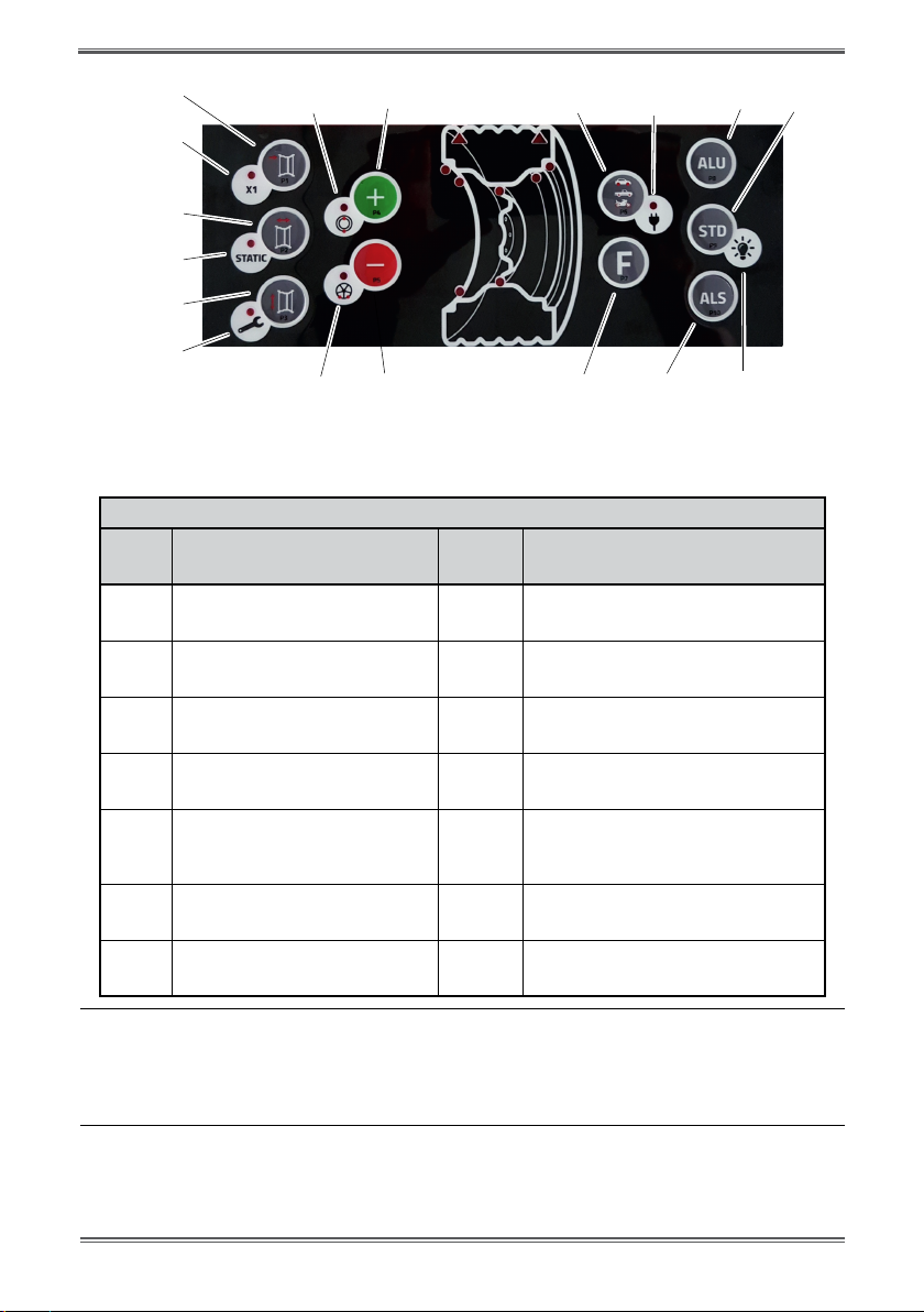
1. CONTROLPANEL
The machine control panel is shown in Figure F1.The control panel allows the operator to give commands
and enter or modify data. The same control panel displays the balancing results and machine messages.
The functions of the various sections of the control panel are described in table T1. The rear side of the
control panel contains the CPU-C1 electronic control board that collects, processes and displays data.
FigureF1:ControlPanel.

Balancer Cube Operator’s manual 2
GB
TableT1Functionsofdierentpartsofthecontrolpanel
Position Description
1Indicatorlightforthe selected CAR/SUV Automotor-vehicle/Off-road/MotorbikeWheelType.
Group of three indicator lights (red) indicating the Type of programme selected
2 Indicator light (red) for the selected unit of measure: inches (on) - mm (o).
3 – 8 Display for viewing internal-external imbalance
4 - 9 Indicator light for the internal-external angular imbalance position
5 Active standby status indicator light
6Enabling (on) - disabling (o) indicator light of the automatic acquisition system of the
wheelsize
7Indicator light for the selected Program Type (Standard/Alu/Alu S). Group of three indi-
cator lights (red) indicating the Type of program selected.
10 ALU program selection
11 ALS program selection
12 F key to access the secondary functions of the keys
13 Indicator light of theWeight Imbalance Position. Group of 7 LEDs (red). The position
depends on the Type of Program and the Type of Wheel selected.
14 STD program selection function (indicated in the big circle) and aa light switch function
(indicated in the small circle)
1.1Keypad
In this manual, the keys are numbered for convenience from [P1] to [P10] as shown in Figure F1. In ad-
dition to the reference numbers of the key, the icons of the same keys are displayed to facilitate reading.
The ten buttons have a main function indicated by a symbol in the big circle, and a secondary
function indicated by the symbol in the small circle located alongside. Some of the secondary functions
feature an
LED to indicate their activation.The keys [P7] , [P8] Start and [P10] Stop do not have
a secondary function. The secondary function of the keys is identied in this manual with the codes from
[F+P1] to [F+P9] as shown in Figure 1b.
Secondary functionof the key.
This part consists only of a
graphic symbol. A LED indi-
cates when the secondary
function is activated.
Main function of the key.
This is the sensitive part that
must be pressed.
FigureF1a:Exampleofakeywiththeindicationoftherstandsecondaryfunctions
To access the secondary function of a key, press the key [P7] together with one of the keys for which
you want the secondary function simultaneously and then release both the keys.
3Balancer Cube Operator’s manual
[F+P1]
[P1]
[P2]
[P3]
[F+P2]
[F+P3]
[F+P5] P5
[F+P4] [P4] [P6] [P8]
[P10]
[P7]
[P9][F+P6]
[F+P9]
FigureF1b:Numberingofthesecondaryfunctionsofthekeys
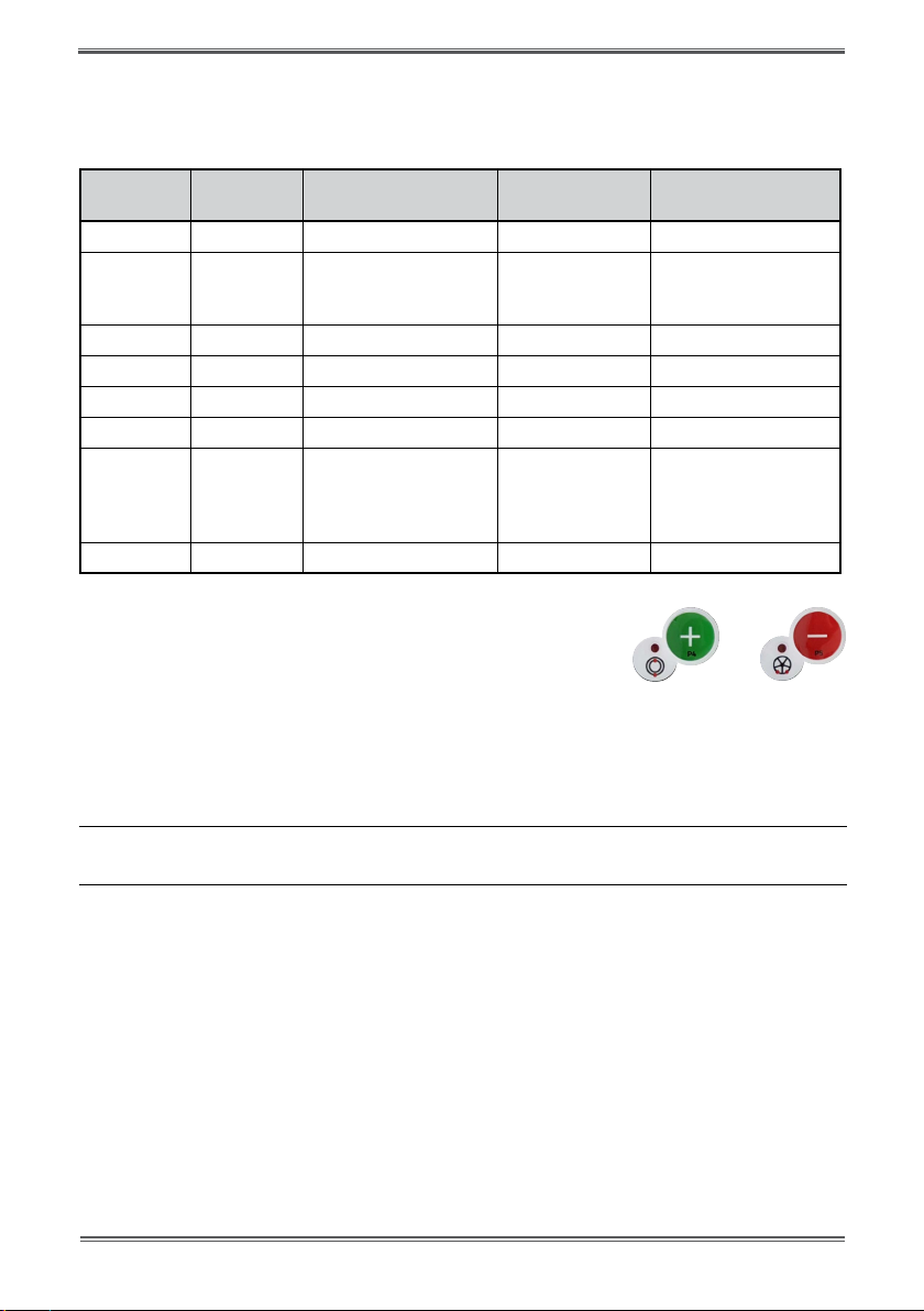
TableT1a,Settings,programsandMenuavailableintheSERVICEmode
SERVICE mode
Key Setting/program or Menu Key Setting/program or Menu
[P1] MENU Program for sensor
calibration [F+P1] Not used
[P2] Not used [F+P2] Select weight material in Fe/Zn, or Pb
[P3] Machine calibration [F+P3] Exit SERVICE mode
(return to the NORMAL mode)
[P4] Select grams/ounces [F+P4] Read counter with the no. of launches
[P5] Select inches/mm [F+P5]
Parameters MENU
(Menu with password reserved for tech-
nical service)
[P6] Select the imbalances threshold
view [F+P6] USB port
Not used
[P9] Not used [F+ P9] Test ProgramsMENU

Balancer Cube Operator's manual 4
GB
1.2NORMAL,SERVICE,STAND-BYoperatingmodes
The machine features three operating modes:
• NORMALmode.Thismodeisenabledwhenthemachineisswitchedonandallowsthemachine to run
wheel balancing;
• SERVICEmode.Inthismode,thereareanumberofutilityprogramsavailabletoentersettings(e.g.
unit of measure in grams or ounces) or controls for machine operation (such as calibration).
• STAND-BYmode.After5minutesofinactivity,themachineautomaticallyswitchestotheSTAND-BYmode
to reduce power consumption. The green STBY LED present on the control panel flashes to indicate that
the machine is in this mode. To exit the STAND-BY mode, press any button (with the exception of [P7]
). All data and settings are maintained in the STAND-BY mode. In SERVICE mode, the machine will
not switch to the STAND-BY mode.

5Balancer Cube Operator’s manual
2. MACHINE START-UP - DIAGNOSTICS
Once the machine is started, it runs the actions shown in diagram below.
Diagram - Program flow at machine start-up
START-UP
YES
NO
NO
NO
YES
YES
View the program name on the left display.
View auxiliary message if necessary.
Machine is ready to operate.
View default data.
View the program release on the right display.
Switch on all LEDs.
Shut-down all electric loads.
Switch on acoustic signal.
Wait two seconds.
Switch on the illuminator.
Switch on the electroma-
gnetic clamping brake.
View error code
Err 015 follo-
wed by the code
ofthe pressed key.
View error code
Err 016 “dis
out”
View error code
Err 021
Release all keys
then switch off
and then on again
Restorethedistan-
ce sensor in the
rest position or
press F+P2
Press any key to
continue, then
enter Calibration
for the CAR/SUV
Wheel Type and/
or calibration for
the MOTOWheel
Type.
Electric
loads =availableonlyonsomemodels
Pressed
keys on the
keypad?
Distance sensor in
the rest position?
Machine
calibrated?
+

Balancer Cube Operator's manual 6
GB
2.1 Temporary disabling of the diameter and distance sensor
(where applicable)
If the machine displays the error code Err 016 “dis out” (distance/diameter sensor not in the rest
position) at start-up, although being in rest position, it means that an anomaly has occurred in the acqui-
sition system.
However, itispossibletoimmediately (and temporarily)disablethe acquisition systembypressing the
button
[F + P2] . The LED [6], located on the control panel, will light up to indicate that
the automatic acquisition system is disabled and that the machine is ready for use.
If you are not abletousetheautomaticacquisitionsystem,sizesofthewheelmustbeentered
manuallyasdescribed in chapters 3.3.1 and 3.3.2. By switching the machine off and then on, the error
code will be displayed again for which it will be necessary to repeat the procedure described above.
3. USE OF THE MACHINE
To use the machine, you must select or set as follows:
• Programtype(programforwheelswithsteel,aluminiumorspecialaluminiumrims).
Default = program for wheels with steel rims;
•WheelType(auto-vehicle,motorbike,off-road).Default=auto-vehicle;
•Dimensionsofthewheeltobalance.Thedimensionscanbeenteredmanually(always)orpartiallyorfully
in automatic (only available on some models).
•DynamicorStaticbalancing.Default=Dynamic;
•DisplayresolutionX1orX5.Default=X5;
The selections described above may be entered before or after the spin. For any variation of the selection or
data settings, the machine will run a recalculation by displaying the new values of imbalance.
Once the selections/settings have been entered, you can run a balance by rotating manually the wheel in
clokwise direction until you hear a beep.
At the end of the balancing, the machine displays the wheel imbalance values.
Apply the weights displayed by the machine at the indicated positions and balance once again. Normally,
the weights should be applied at the 12 o’clock position with the exception of special programsfor ALS2 and
ALS1 aluminium.
+
7Balancer Cube Operator’s manual
3.1 Type of Program (Program Type)
The machine allows the choice between eight different Types of Balancing Programsas listed in table
T3.1
Table T3.1 - Program Types available
Program
type
Wheel
material
Weight position along
the rim section
Automatic
acquisition(1) Notes
STD Steel Default 1sensor Start-up default
ALU1 Aluminium Default 1sensor
Forcibly set when the
motorbike program
type is selected
ALU2 Aluminium Default 1sensor
ALU3 Aluminium Default 1sensor
ALU4 Aluminium Default 1sensor
ALU5 Aluminium Default 1sensor
ALS1 Aluminium
Default for the internal
weight, provided by the
user for the external
weight
1 sensor
ALS2 Aluminium Provided by the user 1 sensor
. Programsare selected in the NORMAL mode by pressing the buttons [P4] or [P5]
At the first selection of one of these two buttons, the currently selected Program Type will appear on
the display; if within about 1.5 seconds, one of these two buttons is not pressed again, the display will
return to the previous state without editing the running Program Type.
Depending on the running Program Type, the following LEDs are lit on the control panel:
• ProgramtypeLEDSeefigureF1,detail[7].
• WeightImbalancePositionLED.SeefigureF1,detail
[13].
Note:
The selection of the STD Program Type removes the selection of the Static imbalance display.
The selected Program Type also influences the automatic acquisition of wheel dimensions (feature avai-
lable only on some models of the machine) as shown in the Automatic acquisition column in table T3.1.
The acquisition that features only 1 sensor uses the Distance/Diameter sensor.

Balancer Cube Operator's manual 8
GB
The position of the balancing weights along the section of the rim in the various Program Types is
shown in Figure F3.1.
Figure F3.1 - Position of the weights in the various Programme Types along the section of the rim
STD ALU4
ALU1 ALU5
ALU2 ALS1
ALU3 ALS2

9Balancer Cube Operator’s manual
Table T3.1.1 Angular position of the balancing weights in the various Program Types
Machine
data
acquisition
system
Program Type
STD,
ALU1,2,3,4,5 ALS1 ALS2
Internal
Plane
External
Plane
Static
Plane
Internal
Plane
External
Plane
Static
Plane
Internal
Plane
External
Plane
Static
Plane
Manual H12 H12 H12 H12 H6 H6 H6 H6 H6
Semi-auto-
matic H12 H12 H12 H12
Sensor-
rim
contact
point (1)
H6
Sensor-
rim
contact
point (1)
Sensor-
rim
contact
point (1)
H6
Automatic H12 H12 H12 H12
Sensor-
rim
contact
point (1)
H6
Sensor-
rim
contact
point (1)
Sensor-
rim
contact
point (1)
H6
Note (1): if the data acquisition system is disabled, the angular position of the weight will be in the 6 o’clock
position.
In table T3.1.1, the symbol H12 indicates that the angular position of the weight is at 12 o’clock while the
symbol H6 indicates that the angular position of the weight is at 6 o’clock.
The machine data acquisition systems are dened as follows:
• Manualwhenthedataoftherimmustall be enteredmanually;
• Semi-automaticwhentheDistanceandDiameterdataareautomaticallyacquiredviatheDistance/Dia-
meter sensor while the data on the Width must be entered manually;
Automatic or Semi-Automatic machines with the sensors disabled (due to failure or for any other
reason) become, for all intents and purposes, Manual machines. Entering the dimensions of the rims must
be carried out manually and the angular position of the balancing weights will follow the procedures of
the Manual machines.
3.2 Wheel type
The machine provides a choice between three different Wheel Types as listed in table T3.2.
Table T3.2 - Wheel Types to select
Wheel type Vehicle Notes
CAR
Auto-vehicles Start-up default

Balancer Cube Operator's manual 10
GB
MOTO
Motorbikes Forcibly set the ALU1 Program
Type
SUV
O-Road vehicles Notsuitable for balancing wheels
of trucks
Each of these programs set specific values for the measurement of the dimensions of the wheel and the
calculation of imbalances. The particularities of each program are indicated in the following paragraphs.
To select a specic Wheel Type, press repeatedly [P6] until the corresponding LED turns on as
shown in the table T3.2.
3.2.1 CAR wheel type (auto-vehicles)
The selection of the CAR Wheel Type provides wheel balancing for auto-vehicles. For off-road vehicles, it
may be appropriate to select the SUV Wheel Type (see paragraph below).
To select the CAR wheel type, press repeatedly [P6] until the CAR LED of the Wheel Type group
LED lights up. See table T3.2.
3.2.2 MOTO wheel type (motorbikes)
The selection of the MOTO Wheel Type provides wheel balancing for motorbikes.
These wheels need to be mounted on the shaft of a special ange. Since the ange pushes the wheel away
from the machine, you must also install a special extension for the distance sensor.
To select the MOTO wheel type, press repeatedly [P6] until the MOTO LED of the Wheel Type
group LED lights up. See table T3.2.
WhentheMOTO wheeltypeis enabled,theALU1 Program Type isautomatically selected andanyattempt
toselect another typeby pressing [P4] or[P5] will be rejected.Thepoint of
applicationof the weights along the rim section is that of the ALU1 Program Type and is indicated in
figure F3.1.When the MOTO Wheel Type is enabled, you can select the display of dynamic or static
imbalance by pres-
sing [F+P2] but if the set width of the wheel is less than 114 mm (or 4.5 inches), the
static imbalance value will be always displayed.
To acquire the geometric data of the wheel automatically with the Distance/Diameter and Width
sensors, you must use the same reference points on the rim of the ALU1 Program Type.
Furthermore, when the MOTO wheel type is enabled, the current distance value is automatically increased
by 150 mm in order to take account of the length of the extension for the Distance sensor.
+
11 Balancer Cube Operator’s manual
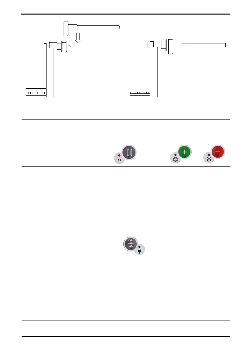
Figure F3.1.1 Application of the extension of Distance/Diameter sensor for measuring MOTO
wheel type
Note:
On machines without an automatic sensor (or on machines where the automatic distance sensor is disabled), the
distancedata must be entered manually. To carry out this operation, you must: : a) place the tip of the extension of the
Distance/Diameter sensor on the rim, b) read the distance value on the graduated scale, c) add 150 mm to the
read value, d)
enter the distance value manually by pressing [P1] and therefore [P4] or [P5] .
Whenever the motorbike ange is removed (e.g. to balance wheels of auto-vehicles) and reassembled after,
make sure the writings “Cal” present on the ange and on the ange for motorbikes are aligned. If this is
not carried out, balancing accuracy may be compromised.
3.2.3 SUV wheel type (off-road vehicles)
The selection of the SUV Wheel Type provides wheel balancing for off-road vehicles. These vehicles are
generally equipped with wheels that are larger than normal and the tire is relatively large compared to the
diameter of the rim (i.e. not low or super low type). However selecting this wheel type, does not allow
the balancing of wheels for trucks because they have rims that are significantly different.
The choice of the CAR or SUVWheelType is at the discretion of the operator who should run balancing tests
to determine which Wheel Type gives the best results for the particular wheel that is subject to balancing.
To select the SUV wheel type, press repeatedly [P6] until the SUV LED of the Wheel Type group
LED lights up. See table T3.2.
All Program Types listed in table T3.2re available for the SUV Wheel Type. Weight
positions along the section of the rim are the same as indicated in Figure F3.
3.3 Entering wheel dimensions
The dimensions of the wheel to balance can be entered in two ways:
• ManualMode.Thismodeisalwaysavailable.
• AutomaticMode.Onlysomemodelsareequippedwithsensorsfortheautomaticentering(partialor
total) of wheel dimensions.
Note:
All machines are equipped with graduated scales for manual measuring of distance.

Balancer Cube Operator's manual 12
GB
3.3.1 Manual entering of the wheel dimensions for the STD and ALU1,2,3,4,5
Program Types
Tointroducethewheelsizemanually,proceedasfollows:
1. Place the wheel on the shaft;
2. Extract the distance sensor and place it on the wheel as shown in Figure F3.3.
3. Read the distance value on the graduated scale as shown in figure F3.3. The distance value is always
expressed in millimetres;
4. Press [P1] to modify the distance and then press [P4] or [P5]
within 1.5 seconds to enter the read value. If you do not press buttons [P4] or [P5] within this time
limit, the
machine will return to the previous display. In this case, you can press [P1] again to enter
or edit data;
5. Measure the width of the wheel with the special gauge or read the value of the width indicated on the
rim. The value of the width can be in inches or millimetres according to the selected unit of measure.
6. Press[P2] tomodifythe width andpress[P4] or[P5] within 1.5seconds
to enter the read value. If either one of these two buttons is not pressed within in this time frame, the
machine will return to the previous screen. In this case, you can press [P2] again to enter or
edit data;
7. Read the value of the diameter indicated on the rim or tyre.The value of the diameter may be expressed
in inches or millimetres according to the selected unit of measure.
8. Press [P3] to modify the diameter value and then press [P4] or [P5]
within 1.5 seconds to enter the read value. If either one of these two buttons is not pressed, in this
time frame, the machine will return to the previous screen. In this case, you can press [P3]
again to enter or edit data;
Figure F3.3 - Manual acquisition of wheel dimensions: placing the Distance sensor

13 Balancer Cube operator’s manual
3.3.2 Manual entering of the wheel dimensions for ALS1 and ALS2 Program
Types
Tointroducethewheelsizemanually,proceedasfollows:
1. Assemble the wheel on the shaft;
2. If the selected program type is ALS1, extract the distance sensor and place it on the wheel as shown in
Figure F3.4, otherwise proceed with step 4.
3. If the selected program type is ALS2, extract the distance sensor and place it on the plane chosen
for the internal weight as shown in Figure F3.4;
4. Read the value of the internal distance of the plane on the graduated scale.The distance value is
always expressed in millimetres;
5. Press [P1] once to view the di1 parameter (distance of the internal plane), and press [P4]
or [P5] within 1.5 seconds to enter the read value. If either one of these two
buttons is not pressed, in this time frame, the machine will return to the previous screen. In this case,
you can press [P1] again, twice in rapid sequence, to enter or edit data;
6. Extract the distance sensor and place it on the plane chosen for the external weight as shown in Figure
F3.5;
7. Read the distance value on the graduated scale. The distance value is always expressed in millimetres;
8. Press [P1] twice in rapid sequence until di2 (distance of the external surface) is displayed
and, within 1.5 seconds, press [P4] or [P5] to enter the read value. If either one
of these two buttons is not pressed, in this time frame, the machine will return to the previous screen.
In this case, you can press [P1] again, twice in rapid sequence, to enter or edit data;
9. Press the button [P3] once to view da1 (diameter of the internal plane), and buttons [P4]
or [P5] within 1.5 seconds to enter the value resulting from one of the two me-
thods described in the note below.
If either one of these two buttons is not pressed, in this time frame, the machine will return to the
previous screen. In this case, you can press [P3] again to enter or edit data;
10. Press the button [P3] twice in rapid sequence to view da2 (diameter of the external
plane), and buttons [P4] or [P5] within 1.5 seconds to enter the value resulting

Balancer Cube Operator's manual 14
GB
from one of the two methods described in the note below. If either one of these two buttons is not
pressed, in this time frame, the machine will return to the previous screen. In this case, you can press
[P1] again, twice in rapid sequence, to enter or edit data;
Note:
The nominal diameter of the wheel does not match with the diameters where the weights are actually applied.
There are two possible methods for determining the da1 and da2 diameters to be entered in steps 9) and 10).
METHOD 1: MANUAL MEASURING OF THE da1 AND da2 DIAMETERS
This method provides for a manual measuring of the da1 and da2 diameters or only the external da2 diame-
ter (depending on the Program Type enabled) with the aid of a ruler as shown in figure 3.3.1. The values to
enter are indicated in table T3.2.1.
Table T3.2.1 Measuring the da1 and da2 diameters for manual entering of the data
Programme Type Internal diameter da1 External diameter da2
ALS1 Enter the nominal diameter of the rim
Enter the actual diameter da2 measured
with the aid of a measuring tape. The
measurement must be performed on the
balancing plane chosen for da2.
ALS2
Enter the actual diameter da1 measured
with the aid of a measuring tape. The
measurement must be performed on the
balancing plane chosen for da1.
Enter the actual diameter da2 measured
with the aid of a measuring tape. The
measurement must be performed on the
balancing plane chosen for da2.
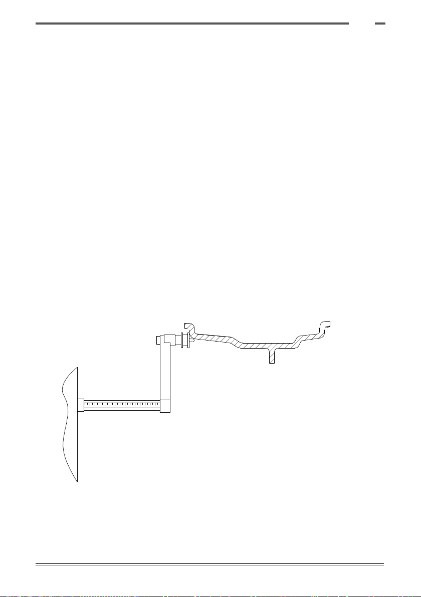
Figure F3.3.1 Example of manual measuring of the external diameter (da2) of the wheel in the
ALS1/ALS2 Program Type
METHOD 2: ENTERING da1 and da2 STARTING FROM THE NOMINAL DIAMETER
This second method is used with the nominal diameter of the rim together with the corrections indica-
ted in table T3.2.2.
Table T3.2.2 Determining diameters da1 and da2 starting from the nominal diameter of the rim
Programme
Type Internal diameter da1 External diameter da2
ALS1 da1 = nominal rim diameter da2=nominaldiameter–2.0inches(or50mm)
ALS2 da1= nominal diameter– 1.0 inch(or25 mm) da2=nominaldiameter–2.0inches(or50mm)
Since manual measuring is not required, this method is faster, but the results may be slightly less accurate.

15 Balancer Cube Operator’s manual
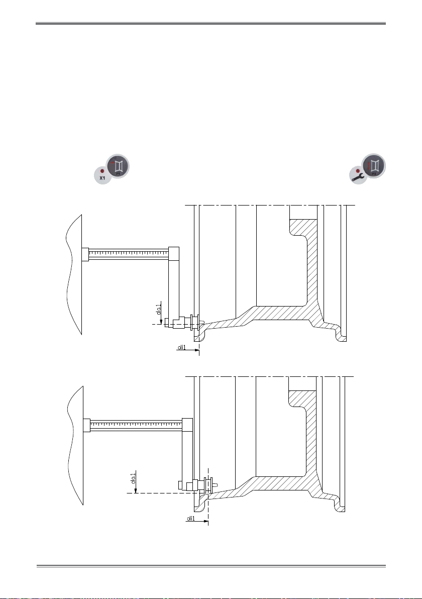
Figure F3.4 - Manual Acquisition of wheel distance in the ALS1 Program Type
Figure F3.5- Manual Acquisition of the internal plane distance in the ALS2 Program Type
FigureF3.6-ManualAcquisitionoftheexternalplanedistanceintheALS1andALS2Program Types
Balancer Cube Operator's manual 16
GB
3.3.3 Automatic acquisition of the wheel dimensions for the STD and
ALU1,2,3,4,5 Program Types
Tointroducethewheelsizeautomatically,proceedasfollows:
3.3.3.1 Machines with distance sensor
1. Place the wheel on the shaft;
2. Extract the Distance/Diameter sensor and place it on the rim as shown in Figure F3.6.
3. Wait to hear the long acquisition beep and then set the Distance/Diameter sensor back to the rest
position;
4. Introduce rim width manually. The width of the rim is normally printed on the rim itself. Alternatively,
use the appropriate width measuring gauge.
FigureF3.6-AutomaticdataacquisitionintheSTD,ALU1,2,3,4,5programs
17 Balancer Cube Operator’s manual
3.3.4 Automatic acquisition of the wheel dimensions for the ALS1 and ALS2
Program Types
To automaticallyenterthedimensionsofthewheelin the ALS1 andALS2Program types,proceedasfollows:
1. Assemble the wheel on the shaft;
2. Extract the Distance/Diameter sensor and place it on the plane chosen as the internal plane. The
point of support differs depending on whether the ALS1 or ALS2 program has been enabled. See
figures F3.7 and F3.8;
3. Wait to hear the long acquisition beep and then set the sensor back to the rest position;
4. Extract the Distance/Diameter sensor and place it on the plane chosen as the external plane. See
figure F3.9;
5. Wait to hear the long acquisition beep and then set the sensor back to the rest position;
6. The dimensions of the wheel have been acquired and the values can be displayed and/or modified
by
pressing [P1] for the di1/di2values (internal/external plane distance) and [P3]
for the da1/da2values (internal/external diameter plane).
Figure F3.7 - Automatic acquisition of the internal plane distance in the ALS1 Program Type
Figure F3.8 - Automatic acquisition of the internal plane distance in the ALS2 Program Type

Balancer Cube Operator's manual 18
GB
FigureF3.9-AutomaticacquisitionoftheexternalplanedistanceintheALS1andALS2Program
Type
3.3.5 Use of the Special Program Types for ALS1 and ALS2 aluminium wheels
The machine features two Special Program Types for aluminium wheels called ALS1 and ALS2. These two
programs are different from the normal Program Types for aluminium wheels (from ALU1 to ALU5)
because they allow the user to select the planes on which apply the balancing weights.This allows you to
balancealuminium wheels with special rim configurations where the use of conventional programs for
aluminium, which require precise weight positioning, would result difficult.
The difference between the ALS1 and ALS2 programmes lies in the fact that , in the ALS1 ProgramType,the
user can freely choose only the external balancing plane (the internal plane is in a predetermined
position) whilst, in the ALS2 Program Type, the user can freely choose both balancing planes.
The ALS1or ALS2 ProgramTypes use only the Distance/Diameter sensor to acquire the balancing planes
chosen by the user. The Width sensor is not used.
Use of the ALS1 or ALS2 Program Types is divided into three parts:
• acquisitionofbalancingplanes;
• balancinglaunch;
• searchofthebalancingplanesforweightapplication.
3.3.5.1 Acquisition of the balancing planes
The two balancing planes are acquired at this stage. During acquisition, the two pairs of distance and
diameter values are stored. These pairs are called di1 and da1 (distance 1 and diameter 1) for the internal
plane and di2 and da2 (distance 2 and diameter 2) for the external plane.
Once acquisition is completed, you can view (and even edit) these two pairs of values by pressing [P1]
for the distance and [P3] for the diameter.
By pressing [P1] , the displaying of the distance values di1 and di2 are alternated. By pressing
[P3] , the displaying of the diameter values da1 e da2 are alternated.
To carry out acquisition, proceed as follows:
1. Select the ALS1 or ALS2 Program Type by repeatedly pressing [P4] or [P5] ;

19 Balancer Cube Operator’s manual
2. Select theplane balancingacquisition modeby pressing[P2] untilthe writingACq is viewed
on the left display as shown in gure F3.10. When the machine is switched on, the acquisition mode
is set by default ;
Fig.F3.10-“Balancingplanesacquisitionenabled”message
3. Extract the Distance/Diameter sensor and place it on the rim that corresponds to the internal
planechosen to apply the balancing weight. See figure F3.7 for the ALS1 Program Type and figure
F3.8 for the ALS2 Program Type;
4. Keep the sensor in the rest position until you hear the acquisition beep. If the sensor is left in the rest
positionafter the beep, further acquisition probing of that plane will be run without entailing
consequences;
5. Set the Distance/Diameter sensor in the rest position immediately. If you hesitate with this operation,
the machine may detect an incorrect plane: in this case, restore the sensor in rest position and repeat
acquisition procedure;
6. Extract the Distance/Diameter sensor and place it on the rim corresponding to the external
planechosen to apply the balancing weight. See figure F3.9;
7. Keep the sensor in the rest position until you hear the acquisition beep. If the sensor is left in the rest
positionfor a longer time, further acquisition probing of that plane will be run without entailing
consequences;
8. Set the Distance/Diameter sensor in the rest position immediately. If you hesitate with this operation,
the machine may detect an incorrect plane: in this case, restore the sensor in the rest position and
repeat acquisition procedure;
3.3.5.2 Balancing start
Once the selections/settings have been entered, you can run a balance by rotating manually the wheel
in clokwise direction until you hear a beep.
3.3.5.3 Search of the balancing planes
The purpose of the balancing planes search is to find the planes previously chosen by the operator in
order to apply the balancing weights. Proceed as follows:
1. Select the balancing planes search mode by pressing [P2] until the writing SrC is viewed
on the left display as shown in gure F3.11.
Fig. F3.11 - “Balancing planes search enabled” message
Table of contents
Other BRIGHT Wheel Balancer manuals


