Sun Microsystems SWB 300 User manual

Manual do Operador Manual do Operador
SWB 300
WHEEL BALANCER
EQUILIBREUSE DE ROUES
EQUILIBRADORA PARA RUEDAS
•OPERATOR’S MANUAL
•NOTICE D’ UTILISATION
•MANUAL DE OPERADOR

ii
Correggio (RE) - ITALYFrancesco Frezza
date:
ENG - complies with all the relevant regulations in the following directives:
FRA - est conforme à toutes les dispositions pertinentes des directives suivantes :
DEU - Allen zu folgenden Richtlinien gehörenden Bestimmungen entspricht:
ITA - è conforme a tutte le disposizioni pertinenti delle seguenti direttive:
POR - satisfaz todas as disposições relevantes das seguintes directivas:
SPA - es conforme con todas las disposiciones pertinentes a las siguientes directivas:
ALB - është konform me të gjitha dispozitat që kanë të bëjnë me direktivat e mëposhtme:
BUL - ••••••••••! "! ••#$%# &!'(•&•)*#, ••)•&+!.# •• • •/•)•!.#•• )#&•%•#•#:
CES - vyhovuje všem požadavk0m, které se vztahují na následující sm1rnice:
HRV - udovoljava svim relevantnim odredbama slijede2ih smjernica:
DAN - er i overensstemmelse med bestemmelserne i følgende direktiver:
EST - vastab järgmiste direktiivide kõikidele asjassepuutuvatele sätetele:
FIN - on seuraavien direktiivien asiaankuuluvien säännösten mukainen:
ELL - 34567 89;<=5> ;3 ?@3J K7J MQ>W@XY37J 8Z3K7[XJ ;3 K7J 6[?@>\]3J >^_`43J:
ISL - er í samræmi við allar viðeigandi tilskipanir eftirfarandi reglugerða:
LAV - atbilst visiem attiecxgajiem noteikumiem š{d{s direktxv{s:
LIT - atitinka visus toliau nurodyt| direktyv| reikalavimus:
}~D - • •• ••€/!•"••• •• •#•• "•&‚# •) •/•)"#•• )#&•%•#•#:
}ON - je u skladu sa svim relevantnim odredbama slede2ih direktiva:
NLD - overeenstemt met alle toepasselijke voorschriften van de volgende richtlijnen:
POL - jest zgodna ƒjest zgodny„ ze wszystkimi zarz…dzeniami zawartymi w nast†puj…cych dyrektywach:
RU} - este fabricat în conformitate cu toate prevederile în materie din urmãtoarele directive:
SLO - vyhovuje všetkým požiadavkám, vz‡ahujúcim sa na nasledujúce smernice:
SLV - v skladu z vsemi predpisi, ki se nanašajo na naslednje direktive:
SˆE - överensstämmer med alla bestämmelser tillhörande följande direktiv:
TUR - a‰aŠ‹da belirtilen yönetmeliklere ili‰kin tüm hükümlere uygundur:
HUN - megfelel a következŒ irányelvekbe foglalt, valamennyi rendelkezésnek:
RUS - ••••••••••Ž•• •••‚ (&#‚•"‘•‚’‚ "•&‚!‚ •/•)Ž“.#” )#&•%•#•:
ENG-The}anagerof the Technical Of•ce is authorisedto compilea technical lea–et in compliancewith appendi— VII, letterA, of the ˜™™›œŸ˜œCE directive
FRA-Le Responsable du Bureau Technique est autorisé à constituer le fascicule technique visé sous l¡anne—e VII lettreA de la directive ˜™™›œŸ˜œCE
DEU-DerLeiterdertechnischenAbteilungistbevollmächtigt,dietechnischenUnterlagenzuerstellenƒsieheAnhangVII,BuchstabeAderRichtlinie˜™™›œŸ˜œCE
ITA-Il Responsabile dell¡Uf•cio Tecnico è autorizzato a costituire il fascicolo tecnico di cui all¡allegato VII lettera A della direttiva ˜™™›œŸ˜œCE
POR-O Responsável do Gabinete Técnico está autorizado a compilar o processo técnico, referido no ane—o VII alínea A da directiva ˜™™›œŸ˜œCE
SPA-ElResponsabledelDepartamentoTécnico está autorizado a constituir el fascículotécnicoindicado en el ane—o VII letraA de ladirectiva ˜™™›œŸ˜œCE
ALB-Përgjegjësi i ¢yrës Teknike është i autorizuar të realizojë fashikullin teknik sipas dokumentit bashkëngjitur VII germa A e direktivës ˜™™›œŸ˜œ~E
BUL-£•€•••&"#%••"!¤•”"#$••%#‘••)•/• Ž(•/"•‚•.•")!••••!•#••”"#$••%!•! *&•¥Ž&!•••••••••••#••¦&#/•+•"#•VII,§A¨,©#&•%•#•!˜™™›œŸ˜œEª
CES-¢odpov1dný pracovník technického odd1lení je oprávn1ný vypracovat technickou dokumentaci podle p«ílohy VII ¬ástiA Sm1rnice ˜™™›œŸ˜œES
HRV-Odgovorna osoba Tehni¬kog ureda je ovlaštena ustrojiti tehni¬ki svezak kako se vidi u dodatku VII slovo A smjernice ˜™™›œŸ˜œCE
DAN-Chefen i den tekniske afdeling har tilladelse til udarbejdelse af den tekniske dokumentation jf bilag VII litra A i direktivet ˜™™›œŸ˜œEF
EST-Tehn oosakonna vastutav töötaja on volitatud koostama teh nilise toimiku v astavalt direkt iivi ˜™ ™›œŸ˜œEÜ VII lis a osale A
FIN-Teknisen toimiston vastuuhenkilö on valtuutettu kokoamaan tekninen eritelmä direktiivin ˜™™›œŸ˜œE- liitteen VII kohdan A mukaisesti
ELL-®¯M39]\5>JK>\°3Z57[>9±Q6<34>\345673²>\87>^>K_;X5>J56M6Q³²37K>5K3Z57[?<³[3@>89;<=56;3K>8\5_;;X5>VII`Q³;;6AK_J>^_`46J˜™™›œŸ˜œ´µ
ISL-Ábyrgðarmanni tækniskrifstofunnar er he imi lt að gera tækniskjalið samkvæmt A-lið VII vi ðau ka í regluger𠘙™›œŸ˜œEB
LAV-Tehnisk{s noda¶as vadxt{js ir pilnvarots sast{dxt tehnisko dokument{ciju atbilstoši ES direktxvas ˜™™›œŸ˜œE~ VII pielikuma A ieda¶ai
LIT-už technin· skyri|atsakingasasmuo yra ·galiotas sudaryti technin† byl…, kurios sudarymotvarka nurodyta Direktyvos ˜™™›œŸ˜œEB VII priedoA dalyje
}~D-£)€•••&"#••"! ••”"#$%#•••))•/ • ••/!•••" )! €• ••••!•# ••”"#$%#••(&#&!$"#% )!)•" •• (&#/•€ VII (#•‚• A •) )#&•%•#•!•! ˜™™›œŸ˜œCE
}ON-Odgovorno lice Tehni¬kog ureda je ovlašteno da sastavi tehni¬ku fasciklu kako se vidi u dodatku VII slovo A direktive ˜™™›œŸ˜œCE
NLD-HetHoofdvandeTechnischeAfdelingisgemachtigdom hettechnischdossiersamente stellenwaaroverinBijlageVII,afdeling A,vanderichtlijn˜™™›œŸ˜œEG
POL-~ierownikBiuraProjektowegojestupowa¸nionydo za¹o¸eniaskoroszytutechnicznego,o którymmowaw ¢a¹…cznikuVIIliteraA dyrektywy˜™™›œŸ˜œUE
RU}-ResponsabilulBirouluiTehnicesteautorizatsãîntocmeascãdosarultehnicprevãzutînane—aVIIliteraAdirectiva˜™™›œŸ˜œCEprivindechipamenteletehnice
SLO-¢odpovedný pracovník technického oddelenia je oprávnený vypracova‡ technickú dokumentáciu podºa prílohy VII ¬astiA Smernice ˜™™›œŸ˜œES
SLV-Vodja tehniènega urada je pooblašèena za sestavo tehniène mape, kot navedeno v prilogi VII, èrka A direktive ˜™™›œŸ˜œES
SˆE-AnsvarigpådettekniskakontoretharbehörighetattsammanställamedföljandetekniskdokumentationienlighetmedavsnittAibilagaVIIidirektiv˜™™›œŸ˜œEG
TUR-Teknik Ofis Sorumlusu ˜™ ™›œŸ˜œEC -önetmeliŠi¡nin VII ekinin A harfinde belirtilen te knik do syay‹ haz‹rlamaya yet kilidir
HUN-A}»szakiIrodaIrodavezetŒjefeljogosította ˜™™›œŸ˜œE~irányelvArészénekVII }ellékletébenmeghatározott,m»szakidokumentációösszeállítására
RUS-¼Ž%•••)#••/½ ••”"#$••%•€• ••)•/! Ž(•/"•‚•$•" ••••!•#•½ ••”"#$••%#¾ /#•• • ••••••••••## • (&#/•+•"#•‚ VII, /#••& A )#&•%•#•’ ˜™™›œŸ˜œCE
ITA-Direttore Operativo SPA-Director Operativo POR-Director Operacional ENG-Operations }anager FRA-Directeur Opérationnel
DEU-Betriebsleiter ALB-Drejtori Operativ BUL-£(•&!•#••" )#&•%••& CES-Výkonný «editel HRV-Operativni direktor DAN-Driftsleder
EST-Tegevdirektor FIN-Operatiivinen johtaja ELL-´M7Z37Q_876[?J ¿73\]\5KÀJ ISL-Starfandi framkvæmdarstjóri LAV-Operatxvais direktors
LIT-Operacij| vadovas }~D-£(•&!•#••" )#&•%••& }ON-Operativni direktor NLD-Operationeel directeur POL-Dyrektor Operatywny
RU}-Director Operator SLO-Výkonný riaditeº SLV-Operativni vodja SˆE-Driftledare TUR-‰letme }üdürü HUN-Operatív Igazgató
RUS - Ã(&!•/‘“.#¾ (&•#'••)••••‚
2006/42/CE
2014/35/CE
2014/30/CE
Snap-on Equipment Srl a unico socio
Via Provinciale per Carpi, 33
42015 CORREGGIO (RE) ITALY
Tel.: +39-(0)522-733480
Fax: +39-(0)522-733479
Internet: http://www.snapon-equipment.eu
ENG - DECLARATION OF CE CONFORMITY
FRA - DECLARATION CE DE CONFORMITE
DEU - KONFORMITÄTSERKLÄRUNG
FIN - EY-VAATIMUSTENMUKAISUUSVAKUUTUS
NLD - VERKLARING VAN OVEREENSTEMMING
SWE - EG-FÖRSÄKRAN OM ÖVERENSSTÄMMELSE
DAN - EF-OVERENSSTEMMELSESERKLÆRING
ISL - EB-SAMRÆMISYFIRLÝSING
POL - DEKLARACJA ZGODNO•CI “CE”
RUM - DECLARA•IE DE CONFORMITATE CU NORMELE CE
SLO - ES VYHLÁSENIE O ZHODE
SLV - IZJAVA O SKLADNOSTI CE
ALB - DEKLARATË KONFORMITETI KE
HUN - EK MEGFELEL•SÉGI NYILATKOZAT
DICHIARAZIONE CE DI CONFORMITA’ - ITA
DECLARAÇÃO CE DE CONFORMIDADE - POR
DECLARACIÓN CE DE CONFORMIDAD - SPA
•••!"#"$%& '" ()*+,•+(+,%• - BUL
ES PROHLÁŠENÍ O SHOD. - CES
DEKLARACIJA CE O PODOBNOSTI - HRV
EÜ VASTAVUSDEKLARATSIOON - EST
/01230 CE 34556782303 - ELL
ES ATBILST9BAS DEKLAR:CIJA - LAV
ATITIKTIES DEKLARACIJA - LIT
“EC” •••!"#"$%;" '" (**<#"'=*(+ - MKD
DEKLARACIJA CE O USKLA>ENOSTI - MON
EC UYGUNLUK BEYANNAMES? - TUR
•••!"#"$%& (**+,•+(+,%& (+"=•"#+"@ •( -
RUS
Snap-on Equipment Srl - Via Provinciale per Carpi, 33 - 42015 Correggio (RE) Italy
ENG - takes full responsibility for declaring that the machineQ
FRA - déclare sous sa propre responsabilité que la machine Q
DEU - erklärt auf eigene VerantwortungX dass die MaschineQ
ITA - dichiara sotto la propria responsabilità che la macchinaQ
POR - declara sob a própria responsabilidade que a máquinaQ
SPA - declara bajo su propia responsabilidad que la máquinaQ
ALB - deklaron nën përgjegjësinë e tij se makineriaQ
BUL - [\]^_`v`_ xz[ z{|z}z`~z€{X ‚\ ƒ_„v~_{_Q
CES - prohlašuje na …lastní †odpo…‡dnostX že strojní †aˆí†eníQ
HRV - i†ja…ljuje pod …lastitom odgo…ornoš‰u da strojQ
DAN - erklærer på eget ans…arX at maskinenQ
EST - kinnitab omal …astutuselX et aparaatQ
FIN - …akuuttaa omalla …astuullaanX että koneQ
ELL - ‹ŒŽ‘•–— ˜™–›œ˜•Ÿ ¡— Œ ¢Œ£Ÿ•¤Q
ISL - lýsir þ…í y¥r á eigin ábyrgð að bíllinnQ
LAV - ap†in¦damies sa…u atbild§bu apliecinaX ka maš§na¨iek¦rtaQ
LIT - prisiimdama atsakomyb© skelbiaX kad mašinaQ
MKD - vª«_}¬}_ xz[ €}z«_ z[|z}z`~z€{ [\]_ ƒ_„v~_{_Q
MON - i†ja…ljuje pod …lastitom odgo…oroš‰u da mašinaQ
NLD - …erklaart …oor eigen …erantwoordelijkheid dat de machineQ
POL - o-wiadc†a na w®asn¯ odpowied†ialno-‰X °e mas†ynaQ
RUM - declarã pe propria rãspundere cã ma±inaQ
SLO - …yhlasuje na …lastnú †odpo…ednos²X že strojo…é †ariadenieQ
SLV - pod lastno odgo…ornostjo i†ja…ljamoX da je strojQ
SWE - försäkrar under eget ans…ar att maskinenQ
TUR - kendi sorumlulu³u alt´nda makinenin a±a³´da belirtilen yönetmeliklere uygun oldu³unu beyan etmektedirQ
HUN - a saját felelµssége tudatában kijelentiX hogy a gépQ
RUS - € xz^~z¶ z{}\{€{}\~~z€{·¸ ª_¹}^¹\{ ‚{z ƒ_„v~_
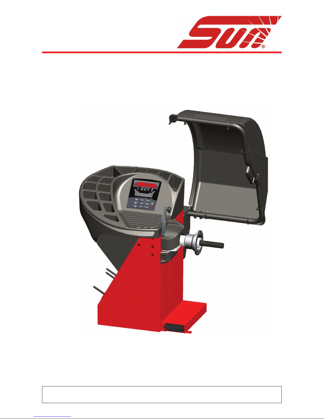
WHEEL BALANCER
EQUILIBREUSE
RADAUSWUCHTGERÄT
EQUILIBRATRICE
MÁQUINA DE EQUILIBRAR RODAS
EQUILIBRADORA
EKUILIBRUESE
!"#$%" &" '"("%)$*"%+ %" ,.!$
VYVAŽOVA/KA
BALANSER
HJULAFBALANCERINGSMASKINE
TASAKAALUSTUSSEADE
TASAPAINOTUSKONE
0123455467873
JAFNVÆGISSTILLINGARVÉL
BALANSÇÐANA
BALANSAVIMAS
$&+9%":.;":
BALANSERKA
BALANCEERMACHINE
WYWA<ARKA
ECHILIBROR
VYVAŽOVA/KA
STROJ ZA URAVNOTEŽEVANJE
BALANSMASKIN
DENGELEY=C=
KERÉKKIEGYENSÚLYOZÓ
'"("%)$*>;>:%?@ )X+%9
EC DECLARATION (Original document contained in Spare Parts Booklet)
DECLARATION CE (Le document original figurant dans le Liste des pièces détachées)
CE KONFORMITÄTSERKLÄRUNG (Originaldokument in der Ersatzteilliste enthaltenen)
ДЕКЛАРАЦИЯ EC (Оригинал документа прилагается к ведомости запчастей)
DICHIARAZIONE CE (Originale contenuta nel Libretto Ricambi)
DECLARACIÓN CE (El original se encuentra en tabla de repuestos)
DECLARAÇÃO CE (O original está contida em Lista de peças)
FAMILY NAME DESCRIPTION
SWB 300 SWB 300L Laser and Sonar system
All Information in this manual has been supplied by the indicated Snap-on Technical Department:
Toutes les informations figurant dans le présent manuel ont été fournies par le Bureau Technique indiqué :
Alle in diesem Handbuch enthaltenen Informationen wurden durch das angegebene Technische Büro von Snap-on geliefert:
Вся информация, содержащаяся в данном руководстве, была доставлена по указанному технической офисе Snap-on:
Tutte le informazioni contenute in questo manuale sono fornite dall’Ufficio Tecnico Snap-on indicato:
Todas las informaciones contenidas en este manual han sido facilitadas por el Servicio Técnico Snap-on indicado:
Todas as informações contidas neste manual foram fornecidas pelo Servicio Técnico Snap-on indicado:
SWB 300 L
SAFETY INFORMATION
For your safety, read this manual thoroughly
before operating with the Wheel Balancer
This Wheel Balancer is intended for use by properly trained automotive techni-
cians. The safety messages presented in this section and throughout the ma-
nual are reminders to the operator to exercise extreme caution when servicing
tires with these products.
There are many variations in procedures, techniques, tools, and parts for ba-
lancing tires, as well as the skill of the individual doing the work. Because of
the vast number of wheel and tire applications and potential uses of the pro-
duct, the manufacturer cannot possibly anticipate or provide advice or safety
messages to cover every situation. It is the automotive technician’s responsi-
bility to be knowledgeable of the wheels and tires being serviced. It is essential
to use proper service methods in an appropriate and acceptable manner that
does not endanger your safety, the safety of others in the work area or the
equipment or vehicle being serviced.
It is assumed that, prior to using the Wheel Balancer, the operator has a tho-
rough understanding of the wheels and tires being serviced. In addition, it is
assumed he has a thorough knowledge of the operation and safety features
of the rack, lift, or floor jack being utilized, and has the proper hand and power
tools necessary to service the vehicle in a safe manner.
Before using this Wheel Balancer, always refer to and follow the safety messa-
ges and service procedures provided by the manufacturers of the equipment
being used and the vehicle being serviced.
IMPORTANT !! SAVE THESE INSTRUCTIONS - DO NOT DISCARD !!

iii
DOCUMENTATION SUPPLIED
GELIEFERTE DOKUMENTATION
DOCUMENTATION FOURNIE
ПОСТАВЛЯЕМЫЕ ДОКУМЕНТЫ
DOCUMENTAZIONE FORNITA
DOCUMENTACIÓN SUMINISTRADA
DOCUMENTAÇÃO FORNECIDA
EC DECLARATION
EC CE KONFORMITÄTSERKLÄRUNG
DECLARATION CE
ДЕКЛАРАЦИЯ ЕС
Wiring Diagram
WD Schaltplan
Schéma électrique
Схема электрических соединений
DICHIARAZIONE CE
EC DECLARACIÓN CE
DECLARAÇÃO CE
Schema Elettrico
WD Esquema Eléctrico
Esquema Eléctrico
Contenuto in SP
Integradas en SP
Conteúdos em SP
Contained in SP
Teil der SP
Contenu dans SP
Содержится в каталоге запчастей
NOTE SULLA DOCUMENTAZIONE - ITA
NOTAS SOBRE LA DOCUMENTACIÓN - SPA
NOTAS SOBRE A DOCUMENTAÇÃO - POR
date of first publication:
date de la première édition:
Datum der Erstveröffentlichung:
data di prima pubblicazione:
fecha de la primera publicación:
data da primeira publicação:
дата первой публикации:
Product aid publication:
WHEEL BALANCER
Zum Produkt gehörendes Dokument:
AUSWUCHTMASCHINEN
Publication de support au produit:
EQUILIBREUSE
Pubblicazione di supporto al prodotto:
EQUILIBRATRICE
Publicación de soporte al producto:
EQUILIBRADORA
Documentação de apoio ao produto:
MÁQUINA DE EQUILIBRAR RODAS
Публикация для поддержки изделия:
БАЛАНСИРОВОЧНЫЙ СТАНОК
Original language edition in: ITALIAN
Langue d’origine de la publication: ITALIEN
Originalausgabe in: ITALIENISCH
Edizione di lingua originale in: ITALIANO
Edición original en idioma: ITALIANO
Edição original em: ITALIANO
язык оригинального издания: АНГЛИЙСКИЙ
ENG - NOTES REGARDING DOCUMENTATION
DEU -
ANMERKUNGEN ZUR DOKUMENTATION
FRA - NOTES SUR LA DOCUMENTATION
RU - ПРИМЕЧАНИЯ ПО ДОКУМЕНТАЦИИ
ABB. DESCRIPTION CODE LANGUAGE
SIGLE DESCRIPTION CODE LANGUE
KENN. BESCHREIBUNG CODE SPRACHE
Operator’s Manual
Manuel de l’Opérateur ZEEWB119A03
ENG-FRA-DEU
OM Betriebsanleitung
Руководство по эксплуатации
ZEEWB119A08 RU
Spare Parts Booklet ENG-FRA-DEU
SP Liste des pièces détachées TEEWB119A3 ITA-SPA-POR
Ersatzteilliste RU
Safety Booklet (Quick Start) EAZ0103G25A
ENG-FRA-DEU
QS Manuel de Securité EAZ0103G26A ITA-POR-SPA
Sicherheitsvorkehrungen
EAZ0103G27A RU
SIGLA DESCRIZIONE CODICE LINGUA
SIGLA DESCRIPCIÓN CÓDIGO IDIOMA
SIGLA DESCRIÇÃO CÓDIGO IDIOMA
Manuale Operatore
OM Manual de Operador ZEEWB119A05 ITA-SPA-POR
Manual do Operador
Libretto Ricambi ENG-FRA-DEU
SP tabla de repuestos TEEWB119A3 ITA-SPA-POR
Lista de peças RU
Libretto di Sicurezza EAZ0103G25A
ENG-FRA-DEU
SB Manual de Seguridad EAZ0103G26A ITA-POR-SPA
Manual de Segurança
EAZ0103G27A RU
06 / 2016
IMPORTANT SAFETY INSTRUCTIONS
When using this equipment, basic safety precautions should always be followed, in-
cluding the following:
1. Read all instructions.
2. Do not operate equipment with a damaged power cord or if the equipment has been
damaged - until it has been examined by a qualified authorized service technician.
3. If an extension cord is used, a cord with a current rating equal to or more than that of
the machine should be used. Cords rated for less current than the equip- ment may
overheat. Care should be taken to arrange the cord so that it will not be tripped over
or pulled.
4. Always unplug equipment from electrical outlet when not in use. Never use the cord
to pull the plug from the outlet. Grasp plug and pull to disconnect.
5. To reduce the risk of fire, do not operate equipment in the vicinity of open containers
of flammable liquids (gasoline).
6. Keep hair, loose fitting clothing, fingers and all parts of the body away from moving
parts.
7. Adequate ventilation should be provided when working on operating internal combu-
stion engines.
8. To reduce the risk of electric shock, do not use on wet surfaces or expose to rain.
9. Do not hammer on or hit any part of the control panel with weight pliers.
10. Do not allow unauthorized personnel to operate the equipment.
11. Do not disable the hood safety interlock system or bypass the intended operation.
12.
Use only as described in this manual. Use only manufacturer’s recommended attachments.
13. Always securely tighten the wing nut before Spinning the shaft.
14. ALWAYS WEAR SAFETY GLASSES. Everyday eyeglasses only have impact resistant
lenses, they are NOT safety glasses.
15. Balancer is for indoor use only.
SAVE THESE INSTRUCTIONS

iv
UPDATING REPORTS
Table of Contents
Disclaimer of warranties v
1.0 Safety 7
2.0 Speci!cations 9
3.0 Introduction 11
4.0 Layout 15
5.0 Operation 25
6.0 Maintenance 83
7.0 Trouble shotting 87
8.0 Disposing of the unit 115
9.0 Appendix 115
Appendix: Installation Instructions 117
DISCLAIMER OF WARRANTIES
AND LIMITATIONS OF LIABILITIES
While the authors have taken care in the preparation
of this manual, nothing contained herein:
-
modi!es or alters in any way the standard terms
and conditions of the purchase, lease or rental
agreementunderthetermsofwhichtheequipment
to which this manual relates was acquired,
- increases in any way the liability to the customer
or to third parties.
TO THE READER
While every effort has been made to ensure that
the information contained in this manual is correct,
complete and up-to date, the right to change any part
of this document at any time without prior notice is
reserved.
Before installing, maintaining or
operating this unit, please read
this manual carefully, paying extra
attention to the safety warnings
and precautions.
Revision Aof June 2016
First document issue PCN: 16G0160

v
Table des matieres
Aapplication de la garantie v
1.0 Sécurité 7
2.0 Speci!cations 9
3.0 Introduction 11
4.0 Disposition 15
5.0 Utilisation 25
6.0 Entretien 83
7.0 Dépannage 87
8.0 Vente 115
9.0 Annexes 115
Annexe: Instructions d’Installation 117
LIMITES D’APPLICATION DE LA GARANTIE ET
LIMITATIONS DE LA GARANTIE
Bien que les auteurs aient accordé la plus grande
attention à la rédaction du présent manuel, aucun
élément !gurant dans ce dernier:
- ne modi!e les conditions et les termes standards
d’un accord d’achat en crédit-bail ou de location,
aux termes desquels les appareils traités dans
le présent manuel sont achetés,
- ou n’augmente la responsabilité de la société
envers le client ou les tiers.
POUR LE LECTEUR
Bien que tout effort ait été fait pour assurer l’exactitude
des informations !gurant dans le présent manuel,
comme complément ou mise à jour de ce dernier, le
droit d’y apporter des modi!cations à tout moment sans
préavis est réservé.
Avant d’installer, d’entretenir ou d’uti-
liser la machine, lire attentivement le
présent manuel, en faisant particuliè-
rement attention aux avertissements
et précautions de sécurité.
Tabla de contenidos
Vencimiento de la Garantía v
1.0 Seguridad 7
2.0 Especi!caciones 9
3.0 Introducción 11
4.0 Disposición 15
5.0 Funcionamiento 25
6.0 Mantenimiento 83
7.0 Resolución de problemas 87
8.0 Eliminación de la unidad 115
9.0 Anexo 115
Anexo: Instrucciones para la instalacións 117
VENCIMIENTO DE LA GARANTÍA Y
LIMITACIONES DE RESPONSABILIDAD
A pesar de que los autores han prestado la máxima
atención al redactar este manual, se señala que el
contenido del mismo:
- no altera en ningún modo las condiciones y
los términos estándar acordados en la compra
leasing o alquiler, de los aparatos tratados en
este manual.
- ni aumenta bajo ningún concepto la
responsabilidad de la empresa hacia el cliente
o terceros.
PARA EL LECTOR
Aunque se haya prestado la máxima atención con el
!n de garantizar la veracidad de las informaciones
contenidas en el presente manual, al completarlo
o actualizarlo, la empresa se reserva el derecho
de aportar variaciones al documento en cualquier
momento y sin previo aviso.
Antes de la instalación, puesta en
marcha o mantenimiento de este
equipo, por favor lea atentamente
este manual, poniendo una at-
ención especial en los avisos de
seguridad y precauciones.

6
1-1
IMPORTANT!! CONSERVER LES
PRÉSENTES INSTRUCTIONS
Safety
1.0 Safety
Important safety precautions relevant to the unit are
described in the Safety Booklet, refer to Figure 1 – 1.
The Safety Precautions should be fully understood and
observed by every operator. We suggest you store (a
copy) of the Safety Booklet near the unit, within easy
reach of the operator.
The Operator’s Manual will contain specific warnings
and cautions when dangerous situations may be
encountered during the procedures described.
1.1 Typographical conventions
This manual contains text styles intended to make the
reader pay extra attention:
Note: Suggestion or explanation.
CAUTION: INDICATES THAT THE FOLLOWING
ACTION MAY RESULT IN DAMAGE TO THE UNIT
OR OBJECTS ATTACHED TO IT.
WARNING: INDICATES THAT THE FOLLOWING
ACTION MAY RESULT IN (SERIOUS) INJURY TO
THE OPERATOR OR OTHERS.
• Bulleted list:
• Indicates that action must be taken by the operator
before proceeding to the next step in the sequence.
TOPIC (Fn°) = see the Chapter number.
The topic indicated is explained in full in the charter
specifier.
1.2 Manuals for the unit
The unit includes the following documentation:
- Safety Booklet (standard supplement)
- Operator’s Manual
The operator must learn in detail the instructions
contained in them and meticulously observe the
notes HAZARD and CAUTION WARNINGs.
- Spare Parts Booklet
Document used only by the Technical Support staff.
Installation instructions
The installation instructions are in the Appendix of
the Operator Manual.
EC Declaration of Conformity
The EC Declaration is included in the Spare Parts
Booklet.
IMPORTANT!! SAVE THESE
INSTRUCTIONS
¡ IMPORTANTE !
CONSERVE ESTAS INSTRUCCIONES
- Operator’s Manual (Chapter 1 – 9)
The operator must be familiar with it.
- Spare Parts Booklet
Document used only by the Technical Support staff.
Installation instructions
The installation instructions are in the Appendix of
the Operator Manual.
EC Declaration of Conformity
The EC Declaration is included in the Spare Parts
Booklet.
Installation instructions
The installation instructions are in Chapter 9,
Appendices.

7
Sécurité
1.0 Sécurité
Les mesures de sécurité importantes relatives à l’unité
sont décrites dans le Livret de Sécurité et résumées
Figure 1-1.
Chaque opérateur doit totalement comprendre les
mesures de sécurité. Nous suggérons de conserver
une copie du Livret de Sécurité près de la machine à
la portée de l’opérateur.
Le Manuel de l’Opérateur contient des avertissements
et des mesures de prudence spécifiques à des
situations potentiellement dangereuses qui peuvent
se produire durant les procédures décrites.
1.1 Typographie
Ce manuel contient des styles de texte qui vous
demande de prêter une attention particulière :
Remarque : Suggestion ou explication.
MESURE DE PRUDENCE : INDIQUE QUE L’ACTION
SUIVANTE RISQUE D’ENDOMMAGER LAMACHINE
ET DES OBJETS ATTACHES A LA MACHINE.
AVERTISSEMENT : INDIQUE QUE L’ACTION
SUIVANTE RISQUE DE CAUSER DES BLESSURES
(SERIEUSES) A L’OPERATEUR OU AUTRES.
• Liste à puces :
• Indique que l’opérateur doit effectuer une action
avant de pouvoir passer à l’étape suivante de la
séquence.
ARGUMENTO (Fn°) = ir para o número do capítulo.
A actualização indicada è tratada dentro do capítulo
especi!cado.
1.2 Manuels de la machine
La machine est accompagnée des manuels suivants:
- Livret de Sécurité (supplément de norme)
- Manuel d’utilisation (Chapitre 1 – 9) L’utilisateur
doit apprendre dans le détail les instructions que
ce manuel contient et observer scrupuleusement
les remarques, les MISES EN GARDE de danger
et d’ATTENTION
- Tables et Listes des Pièces de Rechange
Document à usage exclusif du personnel
d’assistance.
Instructions pour l’installation
Les instructions pour l’Installation se trouvent dans
l’Appendice du Manuel d’utilisation.
Déclaration de Conformité CE
La Déclaration CE !gure dans la Notice des Pièces
détachées.
Seguridad
1.0 Seguridad
En el Manual de Seguridad se describen todas las
precauciones importantes de seguridad relativas a la
unidad, consultar la Figura 1 – 1.
Las Precauciones de Seguridad deberán ser
entendidas totalmente por el operador. Sugerimos
guardar una copia del Manual de Seguridad cerca de
la unidad, al alcance del operador.
El Manual del Operador contiene avisos especí!cos y
precauciones para las posibles situaciones de peligro
que puedan surgir durante los procesos descritos.
1.1 Estilo Tipográ!co
Este manual contiene estilos de texto que invitan a
prestar especial atención:
Nota: Facilita sugerencias o explicaciones.
ATENCIÓN: INDICA QUE LA ACCIÓN EN
CUESTIÓN PUEDE DAÑAR LAS UNIDADES
O LOS OBJETOS A LOS CUALES ESTÁN
CONECTADOS.
ATENCIÓN: INDICA QUE LA SIGUIENTE ACCIÓN
PUEDE CAUSAR DAÑOS (GRAVES) AL
OPERADOR O A OTRAS PERSONAS.
• Lista con viñetas:
•
Indica la acción que debe realizar el operador antes de
poder proceder con la siguiente fase de la secuencia.
ARGUMENTO (Fn°) = véase el capítulo N º.
El argumento se desarrolla ampliamente en el capítulo
especi!cado.
1.2 Manuales correspondientes a
la unidad
La unidad incluye la siguiente documentación:
- Manual de Seguridad (suplemento estándar)
- Manual de Operador
El operador debe conocer perfectamente las
instrucciones contenidas en estos manuales
y respetar escrupulosamente las notas y las
ADVERTENCIAS de peligro y de ATENCIÓN.
- Manual de Recambios
Documento para uso exclusivo del personal técnico.
Instrucciones para la Instalación
Las instrucciones para la instalación se hallan en
el Apéndice del Manual de Operador.
Declaración de conformidad CE
La declaración CE forma parte del Manual de
Recambios.
- Manual de Operador (Capítulo 1 – 9)
El operador debe conocer hasta el mínimo detalle.
- Manual para laAsistencia (Tablas y listas de Piezas
de Repuesto)
Documento para uso exclusivo del personal técnico.
Instrucciones para la Instalación
Las instrucciones para la instalación se hallan en
el Apéndice del Manual de Operador.
Declaración de conformidad CE
La declaración CE forma parte del Manual de
Recambios.
Instrucciones para la Instalación
Las instrucciones para la instalación se hallan en
el Cap. 9 Anexos
- Manuel d’utilisation (Chapitre 1 – 9)
L’opérateur doit se familiariser avec ce manuel
- Tables et Listes des Pièces de Rechange
Documentàusageexclusifdupersonneld’assistance.
Instructions pour l’installation
Les instructions pour l’Installation se trouvent dans
l’Appendice du Manuel d’utilisation.
Déclaration de Conformité CE
La Déclaration CE !gure dans la Notice des Pièces
détachées.
Instructions pour l’installation
Les instructions pour l’Installation se trouvent au
Ch.9, Annexes.

8
Speci•cations
2.0 Speci!cations
Power:
Power Supply
Power consumption
Motor rating
Mains fuses
Protection class
Measurements:
Measuring time
Measuring speed
Offset
Resolution
Wheel dimensions:
Max. width
Max. diameter
Max. weight
Rim width
Rim diameter:
-Automatic / Manual
-SMART SONAR
Shaft:
Stub shaft diameter
Dimensions:
Weight
Shipping weight
Max. Dimensions (wxdxh)
Shipping dimensions:
Miscellaneous:
Noise level
2.1 Conditions
During use or long term storage, the conditions should
never exeed:
Temperature range
Humidity range
non condensing
230V~, 50/60 Hz, 1 ph
1,1 A
0,12 KW
(2x)IEC 127 T 6,3A
IP54
>6 sec.
200 rpm
0–250 mm
1/5 g (0,05/0,25 oz)
20” (508 mm)
42” (1050 mm)
70 Kg (154 lbs)
3-20” (76-508 mm)
8-25” / 8-32”
13-26”
40 mm
120 Kg
150 Kg
1313x868x1834 mm
[300L] 1124x1054x1262 mm
<70 db(A)
0-50 °C
10-90%

9
Speci•cations
2.0 Speci•cations
Données électrices :
Alimentation
Consommation électrique
Puissance moteur
Fusibles
Classe de protection
Mesures :
Durée des mesures
Vitesse rotation
Ecart
Résolution
Dimensions de roue :
Largeur max.
Diamètre max.
Poids max.
Largeur de la jante
Diamètre de la jante:
-Automatique / manuel
-SMART SONAR
Arbre :
Diamètre de bout d’arbre
Misure:
Poids
Poids d’expédition
Dimensions max. (lxdxh)
Dimensions d’expédition:
Divers :
Niveau sonore
2.1 Conditions
Lors d’une utilisation ou un stockage prolongé les
conditions ne doivent jamais dépasser :
Gamme de températures
Gamme d’humidité
sans formation de buée
Especi•caciones
2.0 Especi•caciones
Potencia eléctrica:
Alimentador
Consumo eléctrico
Potencia motor
Fusibles red eléctrica
Tipo de Protección
Mediciones:
Tiempo de Medición
Velocidad de Medición
Offsets
Resolución
Dimensiones de la rueda:
Ancho máx.
Diámetro máx.
Peso máx.
Ancho de la Llanta
Diámetro de la LLanta:
- automática / manual
- SMART SONAR
Eje:
Diám. Cabeza del Árbol
Dimensiones:
Peso
Peso de envío
Dimensiones máx. (wxdxh)
Dimensiones de envío:
Varios:
Nivel de ruido
2.1 Condiciones
Durante su uso o almacenamiento prolongado, jamás
se deberán sobrepasar las condiciones:
Nivel de Temperatura
Nivel de Humedad
no condensado
230V~, 50/60 Hz, 1 ph
1,1 A
0,12 KW
(2x)IEC 127 T 6,3A
IP54
>6 sec.
200 rpm
0–250 mm
1/5 g (0,05/0,25 oz)
20” (508 mm)
42” (1050 mm)
70 Kg (154 lbs)
3-20” (76-508 mm)
8-25” / 8-32”
13-26”
40 mm
120 Kg
150 Kg
1313x868x1834 mm
[300L] 1124x1054x1262 mm
<70 db(A)
0-50 °C
10-90%
230V~, 50/60 Hz, 1 ph
1,1 A
0,12 KW
(2x)IEC 127 T 6,3A
IP54
>6 sec.
200 rpm
0–250 mm
1/5 g (0,05/0,25 oz)
20” (508 mm)
42” (1050 mm)
70 Kg (154 lbs)
3-20” (76-508 mm)
8-25” / 8-32”
13-26”
40 mm
120 Kg
150 Kg
1313x868x1834 mm
[300S, 300L] 1124x1054x1262 mm
<70 db(A)
0-50 °C
10-90%

10
Introduction
3.0 Introduction
This wheel balancer combines advanced, high-
performance technology, robustness and reliability with
very simple, user-friendly operation.
It is characterised by a display and input panel which
are easy to use and guarantee rapid, intuitive operation.
Operator time and effort are reduced to a minimum,
while maintaining accuracy and reliability.
Always work in a clean area and with clean wheels,
no dirt stuck in the tyre or on the rim. That way proper
mounting of the wheel and an optimal balancing result
can be achieved.
Application
The off-the-vehicle wheel balancer is designed for
dynamic and static balancing of passenger car and
light-truck wheels, that fall within the limits stated in
the technical speci!cations.
Thisisa high accuracymeasuringdevice. Handle with care.
The wheel balancers “P” (Power clamp) are identical
with the respective standard balancers, except for the
electro–mechanical power clamping device (F5.2,
5.3, 5.13, 7.1.3).

11
Introduction
3.0 Introduction
Cette équilibreuse vous offre une technologie avancée
de haute performance, solidité et fiabilité et son
opération est très simple et conviviale.
Son Clavier af!cheur, simple à utiliser vous assure une
opération rapide et intuitive.
Le temps et l’effort d’utilisation sont réduits au minimum
mais la précision reste constante.
Travaillez toujours dans un endroit propre avec des
roues propres, pas de pneus ou jantes sales. Ainsi
vous obtiendrez une installation correcte de la roue
et des résultats d’équilibrage parfaits.
Application
Cette équilibreuse roues démontéespermet de mesurer
ledéséquilibre dynamique et statique des roues de
voitures et de camionnettes, qui se trouvent dans les
limites mentionnées des spéci!cations techniques.
Ceci est un appareil de mesure de haute précision.
Manipuler avec soin.
L’équilibreuse “P” est identiques aux équilibreuses
standard relatives, sauf les caractéristiques concernant
le moyen de serrage à actionnement électromécanique
Power Clamp (F5.2, 5.3, 5.13, 7.1.3).
Introducción
3.0 Introducción
Esta equilibradora de ruedas combina una tecnología
avanzada y de alto rendimiento, robustez y con!anza,
con un funcionamiento sencillo y fácil de manejar.
Está caracterizada por un display fácil de usar y un
panel de mandos que aseguran operatividad rápida
e intuitiva.
El tiempo y el esfuerzo del operador están reducidos
al mínimo, manteniendo precisión y !abilidad.
Para un correcto montaje de la rueda y un óptimo
resultado de equilibrado, trabajar siempre en un área
limpia y con ruedas limpias, eliminando la suciedad
de los neumáticos y de las llantas.
Aplicación
La equilibradora de ruedas fuera del vehículo esta
diseñada para un equilibrio dinámico y estático de
ruedas de turismos y camiones ligeros, dentro de los
límites descritos en las especi!caciones técnicas.
Éste es un dispositivo de medida de alta precisión:
manejar con cautela.
Con excepción del dispositivo electromecánico de
!jación Power Clamp que sirve para !jar las ruedas, las
equilibradoras “P” son idénticas a los modelos básicos
(F5.2, 5.3, 5.13, 7.1.3).

12
3.1-1
EAA0263G66A
EAM0005D45A
EAM0005D54A
EAC0058D08A
EAC0058D07A
EAC0058D15A
EAM0005D25A
EAM0005D24A
EAM0005D23A
EAM0005D40A
8-04250A
EAA0247G21A
Accessories
3.1 Accessories
Refer to Figure 3.1-1.
The standard accessories are:
Quick-Release Hub Nut
Power Clamp Nut
Plastic Sleeve
Spacer ring
Universal drum
Universal drum cushion
Large cone
Medium cone
Small cone
User Calibration weight
Weight pliers
Caliper

13
EAA0263G66A
EAM0005D45A
EAM0005D54A
EAC0058D08A
EAC0058D07A
EAC0058D15A
EAM0005D25A
EAM0005D24A
EAM0005D23A
EAM0005D40A
8-04250A
EAA0247G21A
EAA0263G66A
EAM0005D45A
EAM0005D54A
EAC0058D08A
EAC0058D07A
EAC0058D15A
EAM0005D25A
EAM0005D24A
EAM0005D23A
EAM0005D40A
8-04250A
EAA0247G21A
Accessoires
3.1 Accessoires
Se reporter à la Figure 3.1-1.
Les accessoires standard sont:
Manivelle de serrage rapide
Embout de blocage Power Clamp
Manchon en plastique
Disque de distance
Coupelle plastique
Joint protection de la coupelle
Grand cône
Cône moyen
Petit cône
Masse de calibrage utilisateur
Pince à masses
Calibre largeur jantes
Accessorios
3.1 Accesorios
Consultar lao Figura 3.1-1.
Los accesorios normales son:
Tuerca rapida
Tuerca Power Clamp
Manguito de plástico
Espaciador
Tambor Universal
Amortiguador tambor universal
Cono grande
Cono medio
Cono pequeño
Masa de Calibración de Usuario
Alicates para pesos
Compás

14
4-1
31
4-2
2
1
23
4-3
Layout
4.0 Layout
Refer to Figure 4-1.
Functional description of the unit:
1. Display
Refer to Chapter 4.1.
2. Input panel
Refer to Chapter 4.2.
3a Internal gauge arm
3b External Detector - Sonar
4. Flange
5. Stub shaft
6. Weight compartments
7. Storage areas for cones and hub nuts
8. Wheel guard
9. Brake Pedal
10.Laser Pointer (F4.6)
Refer to Figure 4-2.
1. Mains switch (ON/OFF)
2. Fuse holder
3. Power inlet
Refer to Figure 4-3
Power clamping device
1 Basic body of clamping device (Flange)
2 Chuck and clamping jaws
3 Clamping sleeve and head
4
5
10
3a
6
8
2
1
9
7
3b

15
Disposition
4.0 Disposition
Se reporter à la Figure 4-1.
Description fonctionnelle de la machine :
1. Af!chage
Se reporter au Chapitre 4.1
2. Clavier
Se reporter au Chapitre 4.2
3a Jauge de déport interne
3b Capteur externe - Sonar
4. Montage
5. Embout d’arbre
6. Bac porte-plombs
7.
Zones de stockage pour cônes et outils de blocage
8. Carter de roue
9. Pédale de frein
10.Pointeur Laser (F4.6)
Se reporter à la Figure 4-2.
1. Interrupteur secteur (ALLUMÉ / ÉTEINT)
2. Porte-fusible
3. Branchement electrique
Se reporter à la Figure 4-3
Moyen de serrage power clamp
1 Corps de base du moyen de serrage (Montage)
2 Mandrin avec mors de serrage
3 Douille et tête de serrage
Disposición
4.0 Disposición
Hágase referencia a la Figura 4-1.
Descripción funcional de la unidad:
1. Pantalla
Consultar Capítulo 4.1.
2. Panel de mandos
Consultar capítulo 4.2.
3a Brazo de medición interno
3b Detector externo - Sonar
4. Brida
5. Árbol terminal
6. Compartimentos porta pesos
7. Zonas de almacenamiento para conos y virolas
8. Protección rueda
9. Freno de la rueda
10.Puntero Laser (F4.6)
Haga referencia a la Figura 4-2.
1. Interruptores red eléctrica (ON/OFF)
2. Soporte fusibles
3. Toma de alimentación
Haga referencia a la Figura 4-3
Útil de !jación Power clamp
1 Cuerpo base del útil de !jación (Brida)
2 Mandril con garras de sujeción
3 Manguito tensor con caja de compresión

16
4-5
4-4
Layout
4.1 The display
See Figure 4-4.
Note: Positions related to the left plane of the
wheel are numbered with an “a”, right
plane positions with a “b” (e.g. 1a, 1b).
1. Plane adjustment rotation indicators
The indicators indicate the direction in which the
operator must turn the wheel (by hand) after a
balancing operation.
2. Weight Application Position (WAP) indicator.
The indicator will light up when the wheel is in the
correct position for weight application. This indicator
will be referred to as the WAP indicator. See the
weight mode selected before applying a weight!
3. Display.
According to the program status, the display
provides the operator with information regarding the
dimensions of the wheel rim, the balance weights,
error codes etc.
4. Power indicator.
As soon as the unit is switched on and powered up,
this indicator will light.
5. Minimization indicator “M”.
The indicator will light if the minimization mode has
been selected.
6. Weight units indicator, “Oz”.
The indicator will light if the weight is displayed in
ounces instead of grams.
7. Dimension Unit Indicator, “mm / PAX”.
If this indicator is ON, the wheel diameter and width
measurements are displayed in millimetres, instead
of inches (default). The indicator also confirms the
PAX mode setting when it and the ALU 3 LEDs are
all ON (F5.5.1).
See Figure 4-5.
1. Motorcycle Mode Indicator.
The indicator lights up if the Motorcycle program
is selected.
2. Hidden Weight Mode Indicator (HWM).
The indicator lights up if the HWM program (ALU2P,
ALU3P) is selected.
3. Split Weight Mode Indicator (SWM)
The SWM indicator lights up if the operator has
enabled this program. Use the Split Weight mode
to “split and hide” the weight to be applied in plane
6, Fig. 4-5 behind the spokes.
1 2 3
4 5 6 7 8
1a 2a 3a 4 3b 2b 1b
5 6 7

17
Disposition
4.1 L’Af•chage
Se reporter à la Figure 4-4.
Remarque : Les positions se rapportant au plan
gauche sur la roue sont numérotées avec
un «a», les positions du plan droit avec
un «b» (par ex. 1a, 1b).
1. Indicateurs de position de masses correctives
Les indicateurs montrent la direction vers laquelle
l’opérateur doit faire tourner la roue (manuellement)
après une pose de masses.
2.
Indicateur IPM-Position de la Pose des Masses (WAP).
L’indicateur s’allume quand la roue est dans la
position correcte pour la pose des masses. Cet
indicateur est appelé indicateur IPM.
Se reporter au type de roue sélectionné avant de
poser la masse !
3. Afficheur.
Selon le stade du programme l’afficheur fournit
à l’opérateur des informations concernant les
dimensions de la jante, les poids des masses, les
codes d’erreur, etc.
4. Indicateur Alimentation.
Après la connection et l’allumage de l’unité, cet
indicateur s’allume.
5. Indicateur “M” de minimisation
Cet indicateur s’allume lors de la sélection du mode
de minimisation.
6. Indicateur “Oz” d’unités de poids
Cet indicateur s’allume si le poids est affiché en
onces au lieu de grammes.
7. Indicateur Unité Dimensions, “mm / PAX”
Si l’indicateur est allumé, les dimensions du
diamètre et la largeur de la roue sont affichées
en millimètres, plutôt qu’en pouces (par défaut).
L’indicateur confirme en outre la sélection du mode
PAX quand il est allumé avec les voyants du mode
ALU 3 (F5.5.1).
Se reporter à la Figure 4-5.
1. Indicateur Mode Moto
L’indicateur s’allume quand le programme Moto
est sélectionné.
2. Indicateur Mode Masses Cachées (HWM)
L’indicateur s’allume quand le programme HWM
(ALU2P, ALU3P) est sélectionné.
3. Indicateur Mode Masses divisées (SWM)
L’indicateur SWM s’allume quand l’opérateur a
sélectionné ce programme. Utilisez le Mode Masses
divisées pour “diviser et cacher» derrière les rayons la
masse à appliquer au plan 6, Fig. 4-5.
Disposición
4.1 La Pantalla
Ver Figura 4-4.
Nota: Las posiciones con respecto al plano
izquierdo de la rueda se numeran con una
“a”. Las posiciones del plano derecho,
con una “b” (por ejemplo, 1a, 1b).
1. Indicadores de rotación del plano de corrección.
Los indicadores muestran la dirección en la cual el
operador debe girar la rueda (manualmente) tras
un equilibrado.
2.
Indicador de Posición deAplicación del Peso (WAP).
El indicador se iluminará cuando la rueda esté en
posición correcta para la aplicación del peso. A
este indicador nos referimos con el nombre WAP.
¡Consulte el tipo de rueda antes de aplicar el peso!
3. Pantalla.
Dependiendo de la fase en la que se encuentre el
programa, la pantalla proporcionará al operador
los datos relativos a las dimensiones de la llanta,
los pesos de equilibrado, los códigos de error, etc.
4. Indicador de corriente.
Después de la conexión y puesta en marcha, este
indicador se ilumina.
5. Indicador de Minimización “M”.
Este indicador se ilumina cuando se selecciona el
modo de minimización.
6. Indicador Unidades de Peso, “oz.”.
El indicador se ilumina si el peso en pantalla se
visualiza en onzas en lugar de gramos.
7. Indicador Unidades de Dimensión, “mm / PAX”.
El indicador se ilumina si las dimensiones de
diámetro y ancho de la rueda se visualizan en
milímetros en lugar de pulgadas (por defecto).
Asimismo, el indicador confirma la configuración
del modo PAX cuando se haya encendido junto
con los Led del modo ALU 3 (F5.5.1).
Ver Figura 4-5.
1. Indicador Modo Moto.
El indicador se ilumina si se selecciona el programa
para moto.
2. Indicador Modo Peso Escondido (HWM).
El indicador se ilumina si se selecciona el programa
HWM (ALU2P, ALU3P).
3. Indicador Peso Dividido (SWM).
El indicador SWM se ilumina si el operador ha
activado este programa. Use el Modo Peso Dividido
para “dividir y esconder” detrás de los radios el
peso que se debe aplicar en el plano 6 Figura 4-5.
Sólo es posible acceder al modo SWM si se ha

18
4-6
4-5
Layout
The SWM mode can be accessed only if it has been
previously be activated in the HWM mode.
4, 8
Weight position indicator.
Fit a clip or stick-on weight to the rim indicated when
this plane’s WAP indicator lights up.
5, 6, 7
Weight position indicator.
Fit a stick-on weight at the indicated rim position
when this plane’s WAP indicator lights up.
4.1.1 System signals
Possible beeps:
High:
the unit returns a short high beep after activating
a key (F4.2).
Low:
the unit returns a low beep if an error is detected,
usually together with a system message.
Error messages can also be indicated by means of
acoustic signals.
The service technician can locate and eliminate the
corresponding error by means of the number of tones,
their frequency and duration (long/short) and the length
of the pauses.
4.2 The input panel
Refer to Figure 4-6.
1. Diameter key with indicator
Press to select “rim diameter” mode. The diameter
indicator will light up, the unit will beep. The current
value will be shown on the display and can be
edited.
2. Width key with indicator
Press to select “rim width” mode. The width indicator
will light up, the unit will beep. The current value
will be shown on the display and can be edited.
3. Offset key with indicator
Press to select “offset” mode. The offset indicator
will light up, the unit will beep. The current value
will be shown on the display and can be edited.
Pressing the offset key in HWM enables the
operator to enter the plane reference points again.
1 2 3
4 5 6 7 8
1 2 3
4 5 6 7 8 9
10

19
Disposition
Vouspouvez accéder au mode SWMseulement sivous
avez préalablement effectué un lancement en HWM.
4, 8
Indicateur de position des masses
Appliquer une masse à clip ou adhésive à la
position de jante indiquée quand l’indicateur WAP
de ce plan s’allume.
5, 6, 7
Indicateur de position des masses
Poser une masse adhésive à la position de jante
indiquée quand l’indicateur WAP de ce plan
s’allume.
4.1.1 Signaux du Systèmes
Bips sonores possibles :
Fort :
La machine émet un court et fort signal sonore
lorsqu’une touche est activée (F4.2).
Faible :
La machine émet un faible signal sonore lorsqu’une
erreur est détectée et af!che généralement un message.
Les erreurs peuvent également être signalées par des
tonalités acoustiques. Le technicien de service pourra
identi!er les erreurs de par le nombre de signaux, leur
fréquence et leur durée (longue/courte) pour ensuite
y remédier.
4.2 Le Panneau de Données
Se reporter à la Figure 4-6.
1. Touche diamètre avec indicateur
Appuyer sur cette touche pour sélectionner le mode
«diamètre de jante». L’indicateur diamètre s’allume,
la machine émet un bip sonore. La valeur en cours
est indiquée sur l’écran, elle peut être modi!ée.
2. Touche largeur avec indicateur
Appuyer sur cette touche pour sélectionner le mode
«largeur de jante». L’indicateur largeur s’allume, la
machine émet un bip sonore. La valeur en cours
est indiquée sur l’écran, elle peut être modi!ée.
3. Touche déport avec indicateur
Appuyer sur cette touche pour sélectionner le mode
«déport». L’indicateur déport s’allume, la machine
émet un bip sonore. La valeur en cours est indiquée
sur l’écran, elle peut être modi!ée.
Quand vous appuyez sur la touche déport dans le
Mode Masses Cachées (MMC), l’opérateur peut
entrer à nouveau les points de référence du plan.
Disposición
llevado a cabo el giro en HWM con anterioridad.
4, 8 Indicador de Posición del Peso.
Coloque un peso de sujección o adhesivo en la
posición indicada de la llanta cuando el indicador
WAP de este plano se ilumine.
5, 6, 7 Indicador de Posición del Peso.
Coloque un peso adhesivo en la posición indicada
de la llanta cuando el indicador WAP de este plano
se ilumine.
4.1.1 Señales del sistema
Posibles bips:
Altos:
la unidad devuelve un sonido corto y alto después
de activar la tecla (F4.2).
Bajo:
la unidad devuelve un sonido bajo si se detecta un
error, normalmente con un mensaje de sistema.
Los errores también pueden señalarse mediante tonos
acústicos.
El número de tonos, así como su frecuencia y su
duración (larga/corta) y la duración de las pausas
permiten que el técnico de la Asistencia Técnica
detecte el error y lo solucione.
4.2 El panel de mandos
Ver Figura 4-6.
1. Tecla de Diámetro con indicator
Pulse para seleccionar el modo de “diámetro de
la llanta”. El indicador de diámetro se ilumina y la
unidad emitirá un sonido, bip. El valor actual se
muestra en pantalla para que pueda modi!carse.
2. Tecla de ancho con indicator
Pulse para seleccionar el modo de “ancho de la
llanta”. El indicador de ancho se ilumina y la unidad
emitirá un sonido, bip. El valor actual se muestra
en pantalla para que pueda modi!carse.
3. Tecla de Desequilibrio con indicator
Pulse para seleccionar el modo “desequilibrio”. El
indicador de desequilibrio se ilumina y la unidad
emitirá un sonido, bip. El valor actual se muestra
en pantalla para que pueda modi!carse. Al pulsar
la tecla de desequilibrio en el Modo de Peso
Escondido el operador podrá volver a introducir
los puntos de referencia del plano.

20
4-6
Layout
4. + key
To increase an input value (e.g. rim diameter, offset,
rim width).
Hold down to change the value shown automatically.
5. Enter key
Press to con!rm input (dimension, mode) or save
“user” settings. The unit will beep.
6. - key
To decrease an input value (e.g. rim width, offset,
rim diameter).
Hold down to change the value shown automatically.
7. * key with indicator
Press to scroll along the special modes.
The * key indicator will light up, the unit will beep.
8. Fine key
Press to toggle the read-out accuracy between 5
and 1 grams (0,25 resp. 0,05 oz.). The unit will
beep.
Combined with the * key, it starts the calibration
function.
9. Weight key
Press to select the required weight application
mode (weight mode), the unit will beep.
Combined with the * key, it starts the “user” function.
Note: If pressed for at least three seconds, it recalls
directly the Normal mode (Clip-Clip) and reduces
the number of ALU modes that can be selected
“Quick ALU Mode” (F5.5).
10.Stop key
Press to stop a spinning wheel.
Note:
The STOP key also has an instant stop function.
1 2 3
4 5 6 7 8 9
10
8. Fine key (Lens)
Press to toggle the read-out accuracy between
Normal, i.e. 0,25 oz (5 grams) and Fine i.e. 0.05 oz
(1 gram) regardless of the registered value. The
unit will beep. Release the key to return to normal
accuracy. Combined with the * key, it starts the “user
calibration” function.
Table of contents
Popular Wheel Balancer manuals by other brands

Snap-On
Snap-On Sun SWB 100 Operator's manual

Unitrol
Unitrol AT-26 Instruction booklet

M&B Engineering
M&B Engineering WB 680 Original instruction manual

CEMB
CEMB DWA3500 installation manual

Hofmann Megaplan
Hofmann Megaplan MEGASPIN 420 quick start guide

Atlas Equipment
Atlas Equipment WBT-210 Installation & operation manual