HENNESSY INDUSTRIES Coats 885 Installation instructions

Manual Part No.: 85611582 00
Revision: 05/19
See
Balancing Your
First Tire
on page 1.
885 Wheel Balancer
Safety Instructions
Set Up Instructions
Operation Instructions
Maintenance Instructions
READ these instructions before placing unit in
service. KEEP these and other materials delivered
with the unit in a binder near the machine for ease
of reference by supervisors and operators.
1601 J. P. Hennessy Drive, La Vergne, TN USA 37086 615/641-7533 800/688-6359 www.coatsgarage.com
HENNESSY INDUSTRIES LLC Manufacturer of COATS®, AMMCO® and BADA® Automotive Service Equipment and Tools.

ii • Important: Always read and follow the instructions.
NOTICE
Read entire manual before assembling,
installing, operating, or servicing this
equipment.

Important: Always read and follow the instructions. • iii
Table of Contents
Important Safety Instructions.........iv - vi
Owner’s Responsibility.....................................v
Operator Protective Equipment........................v
Definitions of Hazard Levels.............................v
Safety Notices and Decals...............................vi
Standard Safety Devices..................................vi
*Balancing Your First Tire.......................................1
Principle Operating Parts.......................................2
Kno Yw our Unit..................................................2
Power Switch....................................................3
Operating the Balancer..................................4
Wheel Mounting...............................................4
Standard Back Cone/Collet Mounting...............4
Optional Front Cone/Collet Mounting...............5
Alternate Mounting...........................................5
Control Panel And Display.................................6
Operation Functions Menu...................................7
Use of the Wheel Balancer.................................7
Standard Balancing (clip-on weights)................7
Wheel Dimensions Setting...............................7
Result of the measurement and
weight application..........................9
Balancing with Adhesive Weights (ALU)......10
Wheel Dimensions Setting........................10
Result of the measurement and
weight application.......................11
Balancing With A Mix Of Adhesive and
Clip-On Weights and Static Balancing....12
Static Unbalance.............................................13
Exact Positioning of the Adhesive Weight
By Means Of The Gauge With Clips...........13
Hide The Adhesive Weights (Behind Spoke).......14
Automatic Minimization Of Static Unbalance...14
Unbalance Match Mount Balance.......................15
Setup...........................................................16
Menu Access Diagram.........................................16
Self-Diagnostics.....................................................17
Balancing Machine Calibration................................17
Automatic Gages Calibration.....................18
Distance Gauge Calibration...................................18
Diameter Gauge Calibration..................................19
Adhesive Weight Width........................................20
Diagnostics..................................................21
Inconsistent Unbalance Readings..........................21
Alarm Signal..........................................................21
InstallationInstructions..............................23
Receiving...............................................................23
Standard Accessories............................................23
Features.................................................................23
Specifications........................................................23
Electrical Requirements.........................................23
Floor and Space Requirements..............................24
Unpacking the Unit....................................25
Remove Balancer from Pallet..................................25
Connect to Power.................................................25
Initial Testing..........................................................25
Hood Installation....................................................25

iv • Important: Always read and follow the instructions.
READ ALL INSTRUCTIONS
1. Eye and face protection recommendations:
“Protective eye and face equipment is required to
be used where there is a reasonable probability of
injury that can be prevented by the use of such
equipment.” O.S.H.A. 1910.133(a) Protective gog-
gles, safety glasses, or a face shield must be pro-
vided by the owner and worn by the operator of
the equipment. Care should be taken to see that
all eye and face safety precautions are followed by
the operator. ALWAYS WEAR SAFETY GLASSES.
Everyday glasses only have impact resistant
lenses, they are not safety glasses.
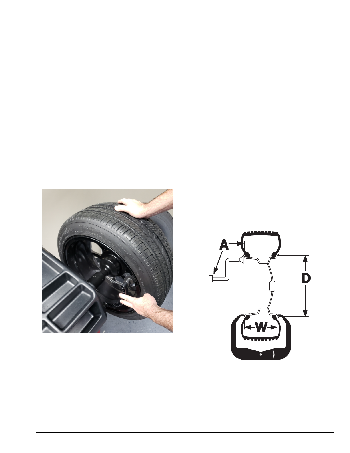
2. Be sure that wheels are mounted properly, the hub
nut engages the arbor for not less than four (4)
turns, and the hub nut is firmly tightened before
spinning the wheel.
3. Read and understand this manual before operat-
ing. Abuse and misuse will shorten the functional
life.
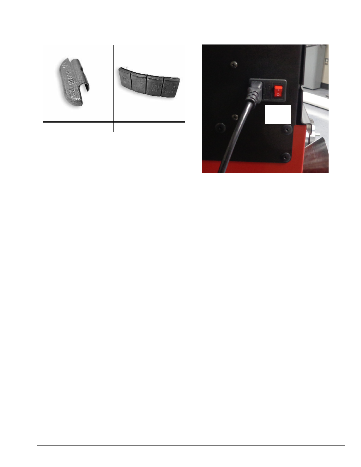
4. Be sure the balancer is properly connected to the
power supply and electrically grounded.
5. Do not operate equipment with a damaged cord or
if the equipment has been dropped or damaged –
until it has been examined and repaired by a quali-
fied serviceman.
6. Do not let cord hang over edge of table, bench, or
counter or come in contact with hot manifolds or
moving fan blades.
7. If an extension cord is necessary, a cord with a cur-
rent rating equal to or more than that of the equip-
ment should be used. Cords rated for less current
than the equipment may overheat. Care should be
taken to arrange the cord so that it will not be
tripped over or pulled.
8. Keep guards and safety features in place and in
working order.
9. Wear proper clothing. Safety toe, non-slip
footwear and protective hair covering to contain
hair is recommended. Do not wear jewelry, loose
clothing, neckties, or gloves when operating the
balancer.
10. Keep work area clean and well lighted. Cluttered
and/or dark areas invite accidents.
11. Avoid dangerous environments. Do not use power
tools or electrical equipment in damp or wet loca-
tions, or expose them to rain.
12. Avoid unintentional starting. Be sure the balancer
is turned off and power disconnected before serv-
icing.
13. Disconnect the balancer before servicing.
14. Use only manufacturer’s recommended acces-
sories. Improper accessories may result in per-
sonal injury or property damage.
15. Repair or replace any part that is damaged or worn
and that may cause unsafe balancer operation. Do
not operate damaged equipment until it has been
examined by a qualified service technician.
16. Never overload or stand on the weight tray or any
part of the balancer.
17. Do not allow untrained persons to operate machin-
ery.
18. To reduce the risk of fire, do not operate equip-
ment in the vicinity of open containers or flamma-
ble liquids (gasoline).
19. Adequate ventilation should be provided when
working on or operating internal combustion
engines.
20. Keep hair, loose clothing, fingers, and all parts of
body away from moving parts.
21. Use equipment only as described in this manual.
22. Use only manufacturer’s recommended attach-
ments and accessories.
IMPORTANT SAFETY INSTRUCTIONS
SAVE THESE INSTRUCTIONS

Important: Always read and follow the instructions. • v
Owner’s Responsibility
To maintain machine and user safety, the responsibil-
ity of the owner is to read and follow these instruc-
tions:
• Follow all installation instructions.
• Make sure installation conforms to all applicable
Local, State, and Federal Codes, Rules, and
Regulations; such as State and Federal OSHA
Regulations and Electrical Codes.
• Carefully check the unit for correct initial function.
• Read and follow the safety instructions. Keep them
readily available for machine operators.
• Make certain all operators are properly trained,
know how to safely and correctly operate the unit,
and are properly supervised.
• Allow unit operation only with all parts in place and
operating safely.
• Carefully inspect the unit on a regular basis and
perform all maintenance as required.
• Service and maintain the unit only with authorized
or approved replacement parts.
• Keep all instructions permanently with the unit and
all decals/labels/notices on the unit clean and visi-
ble.
• Do not override safety features.
Operator Protective Equipment
Personal protective equipment helps make tire serv-
icing safer. However, equipment does not take the
place of safe operating practices. Always wear durable
work clothing during tire service activity. Loose fitting
clothing should be avoided. Tight fitting leather gloves
are recommended to protect operator’s hands when
handling worn tires and wheels. Sturdy leather work
shoes with steel toes and oil resistant soles should be
used by tire service personnel to help prevent injury in
typical shop activities. Eye protection is essential dur-
ing tire service activity. Safety glasses with side
shields, goggles, or face shields are acceptable. Back
belts provide support during lifting activities and are
also helpful in providing operator protection.
Consideration should also be given to the use of hear-
ing protection if tire service activity is performed in an
enclosed area, or if noise levels are high.
Definitions of Hazard Levels
Identify the hazard levels used in this manual with the
following definitions and signal words:
DANGER
Watch for this symbol:
It Means: Immediate hazards, which will result in
severe personal injury or death.
WARNING
Watch for this symbol:
It Means: Hazards or unsafe practices, which could
result in severe personal injury or death.
CAUTION
Watch for this symbol:
It Means: Hazards or unsafe practices, which may
result in minor personal injury or product or property
damage.
Watch for this symbol! It means BE ALERT! Your
safety, or the safety of others, is involved!
CAUTION
WARNING
DANGER

vi • Important: Always read and follow the instructions.
Safety Notices and Decals
Failure to follow danger, warning, and cau-
tion instructions may lead t o serious per-
sonal injury or death to operator or
bystander or damage to property. Do not
operate this machine until you read and
understand all the dangers, warnings and
cautions in this manual. For additional
copies of either, or further information, con-
tact:
Hennessy Industries, Inc.
1601 J.P. Hennessy Drive
LaVergne, TN 37086-3565
(615) 641-7533 or (800) 688-6359
www.coatsgarage.com
Standard Safety Devices
• Stop push button for stopping the wheel under
emergency conditions.
• A hood guard of high impact plastic that is designed
to prevent the counterweights from flying out in any
direction except towards the floor.
WARNING
Model
885
38

Important: Always read and follow the instructions. • 1
Balancing Your First Tire
1. Turn the machine OFF then ON
(resets machine).
Note: The machine wakes up using standard
clip-on wheel weight locations (c1 & c2) and
wheel dimensions.
2. Mount a tire/wheel on the
balancer that will use standard
clip-on wheel weights.
Use the most appropriate mounting method.
3. Always remove any weights
already attached to the wheel.
4. Enter A & D wheel dimensions
using offset arm.
Automatic Measurement — pull offset arm out
to the wheel, hold it still at clip-on weight
position against wheel flange. Return arm to
home position.
5. Enter Width wheel dimension.
Use plastic calipers to measure wheel width.
Use keypad to enter Width value.
6. Lower the hood, press Start;
wheel spins and unbalances are
measured and displayed.
The corrective weight amount appears in the
digital readout windows.
7. Raise hood after tire stops rotat-
ing.
Note: Wait for wheel to stop before raising the
hood.
8. Rotate wheel to inboard (left
plane) position of unbalance.
9. Attach inboard (left plane)
corrective weight.
Attach specified weight amount at top-dead-cen-
ter on inside flange of wheel.
10.Rotate wheel to outboard (right
plane) position of unbalance.
11.Attach outboard (right plane)
corrective weight.
Attach specified weight amount at top-dead-cen-
ter on outside flange of wheel.
12.Lower the hood to respin the
tire/wheel and check balance.
Your weight readings should now be 0.00.
Note: Throughout this manual tire dimensions
are referred to as A, W, and D, see figure 2.
A, W, and D Tire Dimensions
Offset Arm At
Clip-On Weight Location

2 • Important: Always read and follow the instructions.
Principle Operating Parts
Do It Now!
Now is a good time
to fill out the Owner’s
Registry Card.
✓
Know Your Unit
Compare this illustration with the unit before placing
it into service. Maximum performance and safety will
be obtained only when all persons using the unit are
fully trained in its parts and operation. Each user
should learn the function and location, of all controls.
Prevent accidents and injuries by ensuring the unit is
properly installed, operated and maintained.
Control Panel or Video Display Panel
Plug (back of machine)
ON/OFF
Weight Tray with Pockets for Corrective
Weights
Offset Arm, Measures A & D of Tire/Wheel
(shown in home position)
40mm Shaft
Hood Guard
Model 885
Accessory Pegs

Note: Throughout this manual wheel weights are
referred to as Clip-on or Tape-A-Weight™. Figure 3
shows an example of each weight.
Corrective Weight Examples: For Best Results, use BADA®
Brand Wheel Weights.
Power Switch
The ON/OFF switch is located on the back of the
balancer.
Important: Always read and follow the instructions. • 3
Clip-on Weight Tape-A-Weight™
ON/OFF
Power
Switch

4 • Important: Always read and follow the instructions.
Operating the Balancer
Mounting Wheel on Balancer Shaft
Select the most appropriate mounting method for the
wheel you are balancing. Using the proper method
ensures secure mounting and safe balancer operation,
and prevents damage to the wheel.
On most wheels, the inner side of the wheel hub
usually has the most uniform surface for wheel bal-
ancing. Always center the wheel by the most uniform
shaped side of the hub to achieve the most accurate
balance.
Regardless of mounting type, always make sure that
the wheel is forced firmly against the shaft faceplate
and that the hub nut engages the threaded shaft for at
least four complete turns. To assist in centering the
wheel properly, rotate the wheel and the shaft while
tightening the hub nut.
Failure to tighten the hub nut properly may
result in the wheel dismounting, causing
personal injury and property damage.
Standard Back Cone/Collet Mounting
Most original equipment and steel wheels can be
mounted properly using this method. The wheel is cen-
tered on a cone from the inner side of the hub.
1. Select the cone/collet that best fits the center hole
in the wheel. Slide the cone/collet onto the shaft with
the large end towards the cone spring.
2. Lift wheel onto the shaft and center it on the
cone/collet.
3. Attach the pressure cup to the hub nut.Install
the Hub nut assembly onto the shaft and tighten
it securely against the wheel. The wheel must be
forced firmly against the faceplate. The hub nut
must engage the threads for at least four full
turns.
Note: Use a nylon spacer (protective ring) to protect
cus-tom wheel finishes.
Note: If the hub nut will not tighten completely, use
the front cone mounting method.
CAUTION
CAUTION
Avoid back injury, seek assistance when
lifting heavy tire/rim assemblies onto the
balancer shaft.
Standard Back Cone/Collet Mounting
Built in
Spring
Hub Nut with
Pressure Cup
Shaft
Protective
Ring
Faceplate
Cone/Collet

Important: Always read and follow the instructions. • 5
Optional Front Cone/Collet Mounting
A wheel should be centered by the outer side of the
hub only when the inner surface will not provide an
accurate surface to center on.
1. Select the cone that best fits the center hole in the
wheel.
2. Lift the wheel onto the shaft and slide it back
against the shaft faceplate.
3. Slide the cone onto the shaft and into the center
of the wheel. You will need to lift the tire to seat the
cone in the center hole.
4. Install the hub nut (without pressure cup) onto the
shaft. Tighten it securely against the cone. The hub nut
must engage the threads for at least four full turns.
Note: If the hub nut will not tighten completely
because of a lack of threads, use an additional cone as
a spacer between the mounting cone and the hub nut.
The wheel must be forced firmly against the faceplate.
Note: Do not front cone chrome or clad wheels.
Front Cone/Collet Mounting
Cone/Collet
Shaft
Faceplate
Hub Nut with
Pressure Cup
Spacer
Alternate Mounting
If the wheel has a protruding outer hub which will not
permit the use of the pressure cup, or the cup will not
permit the hub nut to engage at least four turns of the
shaft, this alternate method should be used.
1. Place the cone spring onto the balancer shaft with
the large end towards the faceplate.
2. Select the cone/collet that best fits the center hole
in the wheel. Slide the cone/collet onto the shaft with
the large end towards the faceplate.
3. Lift wheel onto the shaft and center it on the cone/
collet.
4. Use the small nylon spacer (no-mar ring) or a cen-
tering cone/collet to press against the outer wheel hub.
5. Install the hub nut (without the pressure cup) onto
the shaft. Tighten securely.
Alternate Mounting
Built in Spring
of Faceplate
Shaft No-Mar
Ring
Faceplate
Cone/Collet Hub Nut with
Pressure Cup

6 • Important: Always read and follow the instructions.
Control Panel And Display
Note:
Only press buttons with your fingers. Never use the weight hammer or other pointed objects to press buttons.
1-2
3-4
5
6
7
8
9
10
11
12
13
14
Push button, selection of correction mode
Push button, unbalance reading
Push button, FUNCTIONS MENU
Push button, menu selection confirmation
Push button, cycle start
Push button, emergency/home
Push button, position repeater
Push button, SPLIT (hidden weight)
Minimum Maximum & Menu Button
Push button, g/oz measuring unit selection
*Default is OFF, see pg16 to turn ON this feature
2
3
9
11
1
6
7
10
8
12
4
14
13
5
Digital readouts, AMOUNT OF UNBALANCE, inside/outside/static
Push button, unbalance reading below the threshold
Digital readouts, POSITION OF UNBALANCE, inside/outside/static

Important: Always read and follow the instructions. • 7
Operation Functions Menu
Use of the Wheel Balancer
STANDARD BALANCING (clip-on counterweights)
Wheel dimensions setting
1. Using the special grip, move the end of gauge against the rim as shown in the figure:
2. While the gauge is moving the following appears:
3. Hold the gauge in position for at least 2 seconds.
MENU - ACOUSTIC SIGNAL), the acquisition of the dimensions is accompanied
If the acoustic signal is enabled ( by a “beep”) Measurement stored:
4. Set the distance and diameter gauge to the home position.
The balancing machine automatically interprets the presence of a rim with clip-on weight correction:

8 • Important: Always read and follow the instructions.
Page left intentionally blank.

Important: Always read and follow the instructions. • 9
Result of the measurement and weight application
If the unbalance is out of tolerance:
1. When the spin is complete, bring the unbalance into correction position by turning the wheel by hand.
The spindle is automatically locked in correction position (if not disabled the wheel lock and for rotation
speeds less than 20 rpm).
If the acoustic signal is enabled ( MENU - ACOUSTIC SIGNAL), a beep will sound when the correction
position has been reached.
2. The symbol is shown on the Display (Item 3+4 on Pg 6) on the side corresponding to the active correction
plane.
3. Manually apply the number of weights shown on the display on the rim at 12 o’clock using clip-on weights:
Round Off Button
CHOSEN
4. After applying the weights, spin the wheel to check the correction made,checking that bothplanes are within
tolerance.
Outside plane
Inside plane

10 • Important: Always read and follow the instructions.
d1 dE
BALANCING WITH ADHESIVE WEIGHTS (ALU)
Wheel dimensions setting
Using the dedicated grip, move the gauge tip up against the inside of the rim and make two consecutive measure-
ments starting from the inside (FI) as shown in the figure. The two preselected positions coincide with the point
where the counterweight is to be applied.
MENU - ACOUSTIC SIGNAL), the acquisition of the dimensions is accompaniedIf the acoustic signal is enabled (
by a “beep”.
Set the gauge to the home position.
The balancer automatically interprets the presence of a rim with adhesive weight correction:
If the wheel dimensions have been entered incorrectly, the parameters can be modified without repeating the
balancing spin:
1. Press:
2. Set the value of the dimensions in sequence:
dI=inside weight distance
aI=inside weight distance
using the buttons .
3. Press the button to confirm the setting and go to the next dimension.
Press the button at any time to interrupt dimension setting and return to the main screen.

Important: Always read and follow the instructions. • 11
Result of the measurement and weight application
If the unbalance is out of tolerance:
1. When the spin is complete, bring the unbalance into correction position by turning the wheel by hand.
The spindle is automatically locked in correction position (if not disabled the wheel lock and for rotation
speeds less than 20 rpm)
If the acoustic signal is enabled ( MENU - ACOUSTIC SIGNAL), a beep will sound when the correction
position has been reached.
2. The symbol is shown on the Display (Item 3+4 on Pg 6) on the side corresponding to the active correction plane.
3. Manually apply on the rim, at 12 o’clock, the amount of weight shown on the display, by using adhesive weights:
Round Off Button
CHOSEN
4. After applying the weights, spin the wheel to check the correction made checking that both planes are within
tolerance.

12 • Important: Always read and follow the instructions.
BALANCING WITH A MIX OF ADHESIVE AND CLIP-ON WEIGHTS AND STATIC BALANCING
3
1245
After dimension acquisition in standard balancing mode, pressing the buttons
you can select one of the following correction modes.
WEIGHT APPLICATION POSITION
Correction type Inside Outside
Clip-on weight at 12 o’clock Clip-on weight at 12 o’clock
Clip-on weight at 12 o’clock Adhesive weight at 12 o’clock
Adhesive weight at 12 o’clock Clip-on weight at 12 o’clock
Adhesive weight at 12 o’clock Adhesive weight at 12 o’clock
STATIC
Adhesive weight at 12 o’clock
After dimension acquisition in ALU mode, pressing the 3
12
buttons, you can select one of the
following correction modes. The adhesive weight application distance and diameter are measured by means of
the automatic gauge, except for the static unbalance where the dimensions acquired are modified following some
fixed parameters.
WEIGHT APPLICATION POSITION
Correction type Inside Outside
Adhesive weight at 12 o’clock Adhesive weight at 12 o’clock
Clip-on weight at 12 o’clock Adhesive weight at 12 o’clock
STATIC
Adhesive weight at 12 o’clock

Important: Always read and follow the instructions. • 13
dIdE
3
STATIC UNBALANCE
The static unbalance is shown on display (1)and the relative correction position on the LED display.
3
1 2 4 5
The correction weight application diameter cannot be set, but is deduced from the dimensions acquired in
standard or ALU mode through interpolation algorithms and the use of fixed parameters. Tolerance control is
the same as for standard balancing, only that it refers to a single correction plane.
EXACT PO SIT IONING OF THE ADHESIVE WEIGHT BY MEANS OF THE GAUGE WITH CLIPS
▪Press if using the correction method with adhesive weights on the inside of the rim.
▪Fit the correction weight in the specific gauge seat with the adhesive part facing upwards.
▪Bring the wheel into correct angular position for the plane to be corrected.
▪If the wheel clamp option is enabled (( MENU’) the wheel is automatically clamped in the correction position.
▪Pull out the gauge until the leds (Item 5 on Pg 6)light up next to the correction weight.
MENU), the attainment of the weight application distance is accompanied by a
If the buzzer is enabled (
beep.
- INSIDE CORRECTION POSITION
- OUTSIDE CORRECTION POSITION
▪Rotate the gauge until the correction weight adheres to the rim.
▪Thefact that the weight application position is no longer vertical is automatically compensated.
To cancel the function, press the button again.
Note: Must press the button to show Static.

14 • Important: Always read and follow the instructions.
HIDE THE ADHESIVE WEIGHTS (Behind Spoke)
Behind Spoke is only possible in the event of static unbalance or ALU external side and is used to hide any
adhesive weights correcting unbalance behind the rim spokes.
.
1. Perform an unbalance measurement spin.
2. Position the static unbalance or outside ALU in the correction position
3. Bring one of the spoke at 12 o’clock and press
4. Turn the wheel in the unbalance rotation direction indicated on the display until the second spoke is at
12o’clock and press the button.
5. Now, turn the wheel to the correction positions indicated by the LEDs and correct the value displayed.
The Autolock function should lock 2 the two locations for correct weights. To return to the normal unbalance
indication, press
AUTOMATIC MINIMIZATION OF STATIC UNBALANCE
This program is designed to improve the quality of balancing without any mental effort or loss of time by the operator.
In fact by using the normal commercially available weights, with pitch of 5in every 5g, and by applying the two
counterweights,which a conventional wheel balancer rounds to the nearest value, there could be a residual static
unbalance of up to 4 g. The damage of such approximation is emphasized by the fact that static unbalance is cause of
most of disturbances on the vehicle. This new function, resident in the machine, automatically
indicates the optimum entity of the weights to be applied by approximating them in an “intelligent” way
according to their position in order to minimize residual static unbalance.
Set the first split unbalance to correction position 1
Correction position 1
Set the second split unbalance to correction position 2
Correction position 2
15
30
15
30
15
30
15
30
button.
See pg 22
for errors 24, 25 & 26
Table of contents
Other HENNESSY INDUSTRIES Wheel Balancer manuals

HENNESSY INDUSTRIES
HENNESSY INDUSTRIES COATS 700 User manual

HENNESSY INDUSTRIES
HENNESSY INDUSTRIES Coats Vero Series User manual

HENNESSY INDUSTRIES
HENNESSY INDUSTRIES Coats 1185 User manual

HENNESSY INDUSTRIES
HENNESSY INDUSTRIES coats 525 User manual

HENNESSY INDUSTRIES
HENNESSY INDUSTRIES coats 1000 User manual

HENNESSY INDUSTRIES
HENNESSY INDUSTRIES coats 1400 2D Use and care manual

HENNESSY INDUSTRIES
HENNESSY INDUSTRIES Coats 1100 User manual

HENNESSY INDUSTRIES
HENNESSY INDUSTRIES coats ProRide Diagnostic User manual

HENNESSY INDUSTRIES
HENNESSY INDUSTRIES Coats IBS 2000 User manual

HENNESSY INDUSTRIES
HENNESSY INDUSTRIES COATS 950 User manual