hestan KEC 30 User manual

INDOOR COOKING
Radiant Cooktop
KEC
Installation Manual

SAFETY DEFINITIONS
THIS INDICATES THAT DEATH OR SERIOUS INJURY MAY
OCCUR AS A RESULT OF NOT OBSERVING THIS WARNING
THIS INDICATES THAT MINOR OR MODERATE INJURY MAY
OCCUR AS A RESULT OF NOT OBSERVING THIS WARNING.
THIS INDICATES THAT DAMAGE TO THE APPLIANCE OR
PROPERTY MAY OCCUR AS A RESULT OF NOT OBSERVING
THIS WARNING.
NOTICE
READ THESE INSTRUCTIONS CAREFULLY AND COMPLETELY
BEFORE INSTALLING OR USING YOUR APPLIANCE TO REDUCE
THE RISK OF FIRE, BURN HAZARD, OR OTHER INJURY. KEEP
THIS MANUAL FOR FUTURE REFERENCE.
Do not store or use gasoline or other flammable vapors and liquids in the vicinity of
this or any other appliance.
Installation and service must be performed by a qualified installer or service agency.
DO NOT REPAIR, REPLACE OR REMOVE ANY PART OF THE APPLIANCE UNLESS
SPECIFICALLY RECOMMENDED IN THE MANUAL. IMPROPER INSTALLATION,
SERVICE OR MAINTENANCE CAN CAUSE INJURY OR PROPERTY DAMAGE. REFER
TO THIS MANUAL FOR GUIDANCE. ALL OTHER SERVICING SHOULD BE DONE BY A
QUALIFIED TECHNICIAN.
INSTALLER: LEAVE THIS MANUAL WITH THE OWNER OF THE APPLIANCE.
HOMEOWNER: RETAIN THIS MANUAL FOR FUTURE REFERENCE.
IF THE INFORMATION IN THIS MANUAL IS NOT FOLLOWED
EXACTLY, A FIRE OR EXPLOSION MAY RESULT CAUSING
PROPERTY DAMAGE, PERSONAL INJURY, OR DEATH.

©2018 Hestan Commercial Corporation
1
EN
When properly cared for, your Hestan appliance will provide safe, reliable service for many
years. When using this appliance, basic safety practices must be followed as outlined below.
IMPORTANT: Save these instructions for the local Utility Inspector’s use.
INSTALLER: Please leave these Installation Instructions with the owner.
OWNER: Please retain these Installation Instructions for future reference.
This appliance is NOT designed for installation in manufactured (mobile) homes or
recreational park trailers. Do NOT install this appliance outdoors.
SAFETY PRECAUTIONS - BEFORE YOU BEGIN
ELECTRICAL SHOCK HAZARD
Disconnect power before installing or servicing appliance. Failure to do so
can result in death or electrical shock.
ELECTRICAL GROUNDING
• This appliance must be grounded. Grounding reduces the risk of electric
shock in the event of a short circuit. Read the ELECTRICAL CONNECTIONS section of
the Installation manual for complete instructions.
• DO NOT ground to a gas pipe.
• DO NOT use an extension cord with this appliance.
• DO NOT have a fuse in the NEUTRAL or GROUNDING circuit. A fuse in the NEUTRAL
or GROUNDING circuit could result in an electrical shock.
TABLE OF CONTENTS
1 SAFETY PRECAUTIONS - BEFORE YOU BEGIN
2 MODEL NUMBERS
2 RATING LABEL
2 REGULATORY / CODE REQUIREMENTS
3 CUTOUT DIMENSIONS AND REQUIREMENTS
5 COOKTOP INSTALLATION
8 ELECTRICAL CONNECTIONS
10 FINAL SETUP
11 PARTS LIST
11 SERVICE

©2018 Hestan Commercial Corporation
2
EN
MODEL NUMBERS
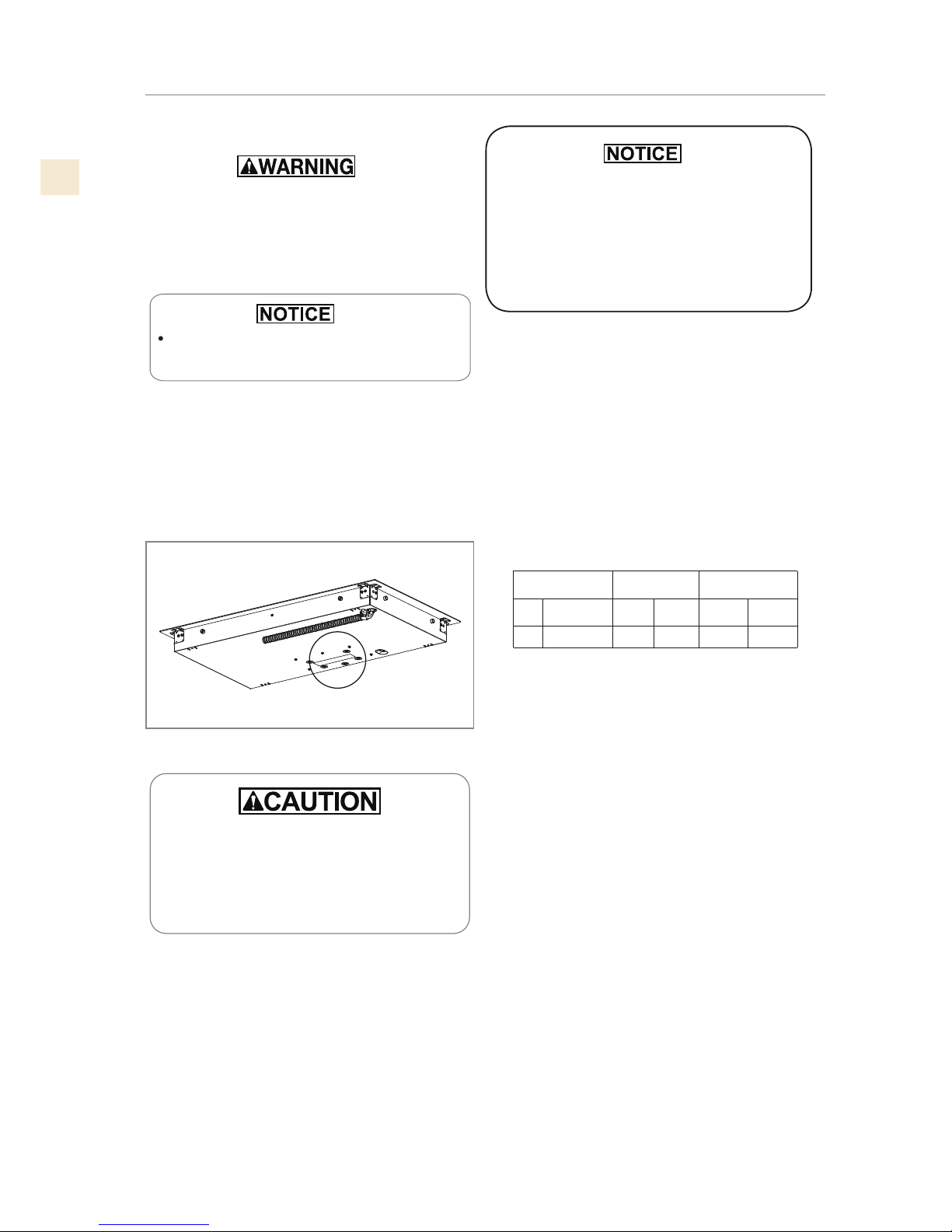
RATING LABEL
The rating label contains important information about your Hestan appliance such as the model and
serial number, electrical rating and the minimum installation clearances.
The rating label is located on the bottom of the cooktop.
If service is necessary, contact Hestan Customer Care with the model and serial number information
shown on the label.
MODEL NO. DESCRIPTION CIRCUIT BREAKER
REQ’D
KEC 30 30” Radiant Cooktop 40 Amp
KEC 30 30” Radiant Cooktop 50 Amp
REGULATORY / CODE REQUIREMENTS
Installation of this cooking appliance must be made in accordance with local codes. In the
absence of local codes, this unit should be installed in accordance with the National Electrical
Code and local codes.
This appliance must be electrically grounded in accordance with local codes or in the absence
of local codes with the National Electrical Code
ANSI/NFPA 70
, or Canadian Electrical code
CSA C22.1
.
RATING LABEL
SERIAL TAG
KEC30-BK
HESTAN COMMERCIAL CORP.
ANAHEIM, CA - USA
TYPICAL RATING LABEL

©2018 Hestan Commercial Corporation
3
EN
Figure 1.
30” 3/8
[77.1 cm] 21” 3/16
[53.8 cm]
3” 1/8
[7.9 cm]
36” 3/16
[91.9 cm] 21” 3/16
[53.8 cm]
3” 1/8
[7.9 cm]
30’’
36’’
A
B
SEE NOTE
R
C
UTOUT DIMENSION
Figure 2.
SLOT FOR
CABLE
ROUTING
3-1/2” [9 cm]
2-1/2” [6.5 cm]
LENGTH OF CUT
FROM EDGE OF CUTOUT
AND FRONT EDGE OF
COUNTERTOP
2-1/2” [6.5 cm]
1-1/4” [3.2 cm] Canadian
2-1/4” [5.7cm] US
LENGTH OF CUT
1-1/2” [3.8CM]
MIN CLEARANCE
CUTOUT DIMENSIONS AND REQUIREMENTS

©2018 Hestan Commercial Corporation
4
EN
D
G
C
E
F
13” [33 cm]
Depth of
unprotected
overhead
cabinets
2” [5 cm] min
Clearance
from cutout to
side wall on
the left and
right of the
unit
30” [76.2 cm]
min.
[see note*]
Clearance
from
countertop to
unprotected
overhead
surface
18” [45.7 cm]
min
Height from
countertop
to nearest
cabinet on
either side of
unit
ABCD E F G
30”
[76.2 cm] min
36”
[91.4 cm] min
19-1/4”
[49.0 cm]
19-5/8”
[49.8 cm]
19-1/4”
[49.0 cm]
19-5/8”
[49.8 cm]
28-11/16”
[72.9 cm]
28 15/16”
[73.5 cm]
34-1/16”
[86.5 cm]
34-5/16”
[87.2 cm]
CUTOUT
WIDTH
30”
[76.2cm]
36”
[91.4 cm]
Figure 3. Cutout dimensions and requirements
Under the cooktop it is necessary to install a partition
as shown ****
IMPORTANT
Important Preparation Suggestions
1. Chamfer all exposed edges of decorative laminate
to prevent damage from chipping.
2. Radius corners of cutout and file to insure
smooth edges and prevent corner cracking.
Recommend 1/4“or 3/8“diameter drill in each
corner.
3. Rough edges, inside corners which have not been
rounded and forced fits can contribute to cracking
of the countertop laminate.
This cooktop has been designed with wide
tolerances of cut-out for when another brand is
being replaced with a Hestan unit. For new
installations, we recommend holding to the
minimum cutout dimensions.
* NOTE
24” [61 cm] min. clearance if bottom of wood or metal
cabinets is protected by not less than 1/4” [0.6 cm] flame
retardant millboard covered with no less than No. 28 MSG
sheet steel 0.015” [0.04 cm] stainless steel, or 0.024” [0.06
cm] aluminum or 0.020” [0.05 cm] copper.
30”[76.2 cm] min. clearance between top of cooking platform
and bottom of unprotected wood or metal cabinet
Dim . Inches cm
28-15/16” x 19-9/16” 73.5 x 49.7
34-5/16” x 19-9/16” 87.2 x 49.7
• 30”
• 36”
WALL COVERING CABINETS,
AND COUNTERTOP MUST
WITHSTAND HEAT UP TO 200°F [93°C]
CUTOUT REQUIREMENTS
CUTOUT DIMENSIONS AND REQUIREMENTS
(CONT.)

©2018 Hestan Commercial Corporation
5
EN
Excessive Weight Hazard
Use two or more people to move and install
cooktop.
Failure to do so can result in back or other injury.
Cut Hazard
Beware of sharp edges. Use the polystyrene ends
when carrying the product. Failure to use caution
could result in minor injury or cuts.
Always consult the countertop manufacturer for
specific instructions.
Ensure the countertop is square and level and
ensure no structural members interfere with space
requirements.
Prepare the cut-out according to the instructions
(see cut-out dimensions).
Make sure the wall coverings, countertop and
cabinets around the cooktop can withstand heat
up to 200°F [93°C].
Figure 4. Tools you will need
Step 1
Remove packaging materials and literature package
from the cooktop before beginning installation.
Remove Installation Manual from literature pack and
read them carefully before you begin.
Figure 5. Packaging and contents
COOKTOP
CARDBOARD
TOP
CARDBOARD
MANUAL
TOP
PACKAGING
GASKET
SCRAPER
BOTTOM
PACKAGING
COOKTOP INSTALLATION

©2018 Hestan Commercial Corporation
6
EN
Step 2
Place a towel or table cloth onto the counter top. Lay
the cooktop upside down onto the protected surface.
Figure 6
Step 3
A foam tape is provided to seal the cooktop edges to the
countertop. Apply tape approximately 1/16” (1.5 mm)
from the glass edge to the underside of the cooktop
glass. Use tape around the entire glass perimeter. Cut
off excess where tape ends meet.
Figure 7
Step 4
Insert the cooktop centered into the cutout
opening. Make sure the front edge of the counter
top is parallel to the cooktop. Make final check that
all required clearences are met.
Figure 8
Step 5
Four clamp brackets are provided to clamp the cooktop
to the countertop. Tighten screws just enough to hold
brackets in place when cooktop is put into cutout.
Tighten screws securely.
Figure 9
COOKTOP INSTALLATION
(CONT.)

©2018 Hestan Commercial Corporation
7
EN
THE CONDUIT IS 3 FEET LONG
The junction box must be located where
it will allow sufficient slack in the conduit
for serviceability.
12” [30.5cm] MIN FROM
BOTTOM OF COUNTERTOP
AND ADJACENT CABINET
(RIGHT SIDE)
COOKTOP INSTALLATION
(CONT.)
• For solid surface material installations such as Surel™ and Corian®, consult with solid surface
manufacturer. Apply heat reflective tape such as Scotch® Aluminum Foil Tape #425 or #427
around the cutout so that it folds over on the top and sides.
• Do not wrap the tape underneath the cooktop.
• Be sure the tape extends beyond the outermost flange of the cooktop. All corners should be
covered with tape.
©2018 Hestan Commercial Corporation
8
EN
Disconnect power before servicing the product.
Failure to do so could result in death or
electrical shock .
General information
The models may be powered at 240V or
208V.
This cooktop does not require a neutral connection. If
the cooktop is to be completely enclosed in a cabinet,
feed the cooktop cable through the opening in the
cabinet. Make the electrical connection following the
appropriate steps for your installation.
Your cooktop must be connected to the proper
electrical voltage and frequency as specified in the
table on the right.
Figure
12. Location of serial tag
SERIAL TAG
National Fire Protection Association
Batter/march Park Quincy, Massachusetts 02269
A three-wire, single phase, 240 Volt 60 cycle electrical
system (properly circuit protected to meet Local
Codes of NFPA No.70) must be provided. Unit must
be properly grounded in accordance with local wiring
code. The chart below recommends the minimum
circuit protector and wire size if the appliance is the
only unit on the circuit. If smaller sizes of wire are
used, the unit efficiency will be reduced and a fire
hazard may be created. It is advisable that the
electrical wiring and hookup be accomplished by a
competent electrician.
This touch control works using optical light sensing
technology. When first connecting electrically or
after a power failure, any direct strong light over the
sensorareamayaffectthetouchcontrol functionality.
When powering on the unit make sure that no strong
light is shining directly over the touch control zone,
it can compromise the start-up sensor calibration
resulting in an unresponsive touch control.
The flexible conduit (supplied) 3 feet long (100 cm)
located at the right rear of the cooktop bottom box
should be connected directly to junction box. Do not
cut the conduit. A U.L - or CSA - listed conduit
connector must be provided at each end of the power
supply cable (at the cooktop and at the junction box.)
A time delay fuse or circuit breaker is recommended.
Do not ground to a gas pipe. Do not have a fuse in the
grounding or neutral circuit.
Fuse both supply (phase) lines.
Improper connection of aluminum house
wiring can result in a re or shock hazard.
Use only connectors designed and certied
for connecting to aluminum wire, and
installed by a qualied electrician.
Model 240 V 60 Hz 208 V 60 Hz
A6.52Wk33.5A6.92Wk1.7
”03
A8.53Wk34.7A3.14Wk9.9
”63
KEC 30**
KEC 36**
Power Supply
ELECTRICAL CONNECTIONS

©2018 Hestan Commercial Corporation
9
EN
ELECTRICAL CONNECTIONS
(CONT.)
Recommended Minimum
kW Rating on
serial plate
Circuit protection
in amperes Wire size
(AWG)
0-4.8
20 12
4.9-6.9
30 10
7.0-9.9
40 8
10.0-11.9
50 8
12.0-14.9
60 6
Be sure your appliance is properly installed and
grounded by a qualified technician. Ask your
dealer to recommend a qualified technician or an
authorized repair service. This cooktop does not
require a neutral connection. If the cooktop Is to
be completely enclosed In a cabinet, feed the
cooktop cable through the opening in the cabinet.
Make the electrical connection following the
appropriate steps for your installation.
This appliance is manufactured with a green ground
wire connected to the cooktop chassis. After making
sure that the power has been turned off, connect the
flexible conduit from the cooktop to the junction box
using a U.L. listed conduit connector. Figures 13 and
14 and the instructions provided below present the
most common way of connecting the cooktops. Your
local codes and ordinances, of course, take
precedence over these instructions. Complete
electrical connections according to local codes and
ordinances
Risk of Electric Shock, frame grounded to
neutral of appliance through a link.
Grounding through the neutral conductor is prohibited
for new branch-circuit installations (1996 NEC);
mobile homes; and recreational vehicles, or in an area
where local codes prohibit grounding through the
neutral conductor.
3-Wire branch circuit
Where local codes allow the connection of ground
wire from the cooktop to the branch circuit neutral wire
(gray or white colored wire) proceed as follows (see
figure 13).
1. If local codes permit, connect the green GROUND
wire from the cooktop to the branch circuit neutral
wire (gray or white colored wire).
2. Connect the red and black leads from the cooktop
to the corresponding leads in the junction box.
4-Wire branch circuit
Refer to figure 14:
Connect the green ground wire from the cooktop
to the ground wire in the junction box (bare or
green colored wire).
Connect the red and black leads from the cooktop
to the corresponding leads in the junction box.
Terminate and insulate the neutral (gray or white
colored wire) in the junction box.

©2018 Hestan Commercial Corporation
10
EN
FINAL SETUP
CLEANUP, VERIFY POWER
Remove any final packaging materials and protective film from all exterior areas.
Check the electrical requirements for the correct electrical supply and that the cooktop is properly
grounded.
Check power at the junction box wires using a voltmeter having a range of 0-250 VAC.
• A 240 Volt supply should read 220 to 240 Volts between the black and red wires (Line to Line).
• A 208 Volt supply should read 190 to 208 Volts between the black and red wires.
FUNCTIONAL TEST
When the cooktop is connected to the electrical voltage supply all lights and digits turn on to
indicate a proper activation. This operation will be completed after few seconds, the control turns
off automatically. Then the cooktop is ready for operations.
1. Switch the Control ON
• If the commands are locked, touch the [LOCK] key for a few seconds. (See that the LOCK led is
on and turns off after a few seconds.)
2. Touch the main [ON/OFF] key to enable the single zones for selection.
• All the displays show power level “0”. If you don’t touch anything else, the control shuts down
again after about 10 seconds.
3. Select a zone and set power
• Touch the ON key (2) for the desired zone: the HOT SURFACE (3) indication starts flashing,
waiting for user input.
4. Touch the slide bar (7) to set the power level (levels 0 to 9). You
can slide your finger along the bar to select the desired value.
• The display (4) and the “Peacock Tail” (6) shows the power level,
updated in real time.
• After a 5 seconds time-out the value is accepted and the HOT
SURFACE led stops flashing.
• The “Peacock Tail” disappears after some seconds more.
5. Verify that the indications perform as above and that the
selected zone begins heating up.
6. Touch the OFF key for the selected zone to turn it off.
7. Touch the main [ON/OFF] key to turn the cooktop off.
Verify that the controls respond as above.
4
1
2
3
TRIPLE DUAL
TIME
OFF
ON
7
6

©2018 Hestan Commercial Corporation
11
EN
SERVICE
All warranty and non-warranty repairs should be performed by qualified service personnel. To locate
an authorized service agent in your zone, contact your Hestan dealer, local representative, or the
manufacturer. Before you call, please have the model number and serial number information ready.
Hestan Commercial Corporation
3375 E. La Palma Avenue
Anaheim, CA 92806
(888) 905-7463
PARTS LIST
Please visit the Hestan website to access the parts list for your Hestan Indoor product:
www.hestanhome.com.
LISEZ ATTENTIVEMENT ET COMPLÈTEMENT CES
INSTRUCTIONS AVANT D’INSTALLER OU D’UTILISER VOTRE
APPAREIL AFIN DE RÉDUIRE LES RISQUES D’INCENDIE, DE
BRÛLURE OU D’AUTRES BLESSURES. CONSERVER CE MANUEL
POUR RÉFÉRENCE FUTURE.
DÉFINITIONS DE SÉCURITÉ
PRÉCAUTION
AVIS
INSTALLATEUR: LAISSER CE MANUEL AVEC LE PROPRIÉTAIRE DE L’APPAREIL.
PROPRIÉTAIRE: CONSERVEZ CE MANUEL POUR RÉFÉRENCE FUTURE.
Ne pas entreposer ni utiliser de I’essence ni d’autres vapeurs ou liquides inflammables dans Ie
voisinage de l’apparell, ni de tout autre appareil.
L’installation et l’entretien doivent être effectués par un installateur qualifié, ou une agence de
service.
NE PAS RÉPARER NI REMPLACER DES PIÈCES DE I´APPAREIL À MOINS QUE CELA NE
SOIT EXPRESSÉMENT RECOMMANDÉ DANS LE MANUEL. TOUTE INSTALLATION,
RÉPARATION OU MAINTENANCE INADÉQUATE PEUT ENTRAÎNER DES BLESSURES OU
DES DOMMAGES MATÉRIELS. CONSULTER CE MANUEL POUR OBTENIR DES CONSEILS
SUR LA FAÇON DE PROCÉDER. TOUS LES TRAVAUX D‘ENTRETIEN DOIVENT ÊTRE
CONFIÉS À UN TECHNICIEN QUALIFIÉ.
L’INOBSERVATION DES INFORMATIONS DONNÉES DANS CE
MANUEL PEUT ENTRAÎNER UN INCENDIE OU UNE EXPLOSION DE
NATURE À CAUSER DES DÉGÂTS MATÉRIELS ET DES BLESSURES
GRAVES, VOIRE MORTELLES.
CECI INDIQUE QUE L’INOBSERVATION DE CET
AVERTISSEMENT PEUT ENTRAÎNER DES BLESSURES GRAVES
VOIRE MORTELLES.
CECI INDIQUE QUE L’INOBSERVATION DE CET
AVERTISSEMENT PEUT ENTRAÎNER DES BLESSURES
MINEURES OU MODÉRÉES.
CECI INDIQUE QUE L’INOBSERVATION DE CET
AVERTISSEMENT PEUT ENTRAÎNER DES DOMMAGES DE
L’APPAREIL OU DES DÉGÂTS MATÉRIELS.

FR
©2018 Hestan Commercial Corporation
1
S’il est bien entretenu, cet appariel Hestan procurera un service sûr et fiable pendant de nombreuses
années. Lorsqu’on se sert de cet appareil, les pratiques élémentaires suivantes en matière de sécurité
doivent être adoptées.
IMPORTANT: Conservez ces instructions pour l’utilisation locale des services publics.
INSTALLATEUR: Veuillez laisser ces instructions d’installation avec le propriétaire.
PROPRIÉTAIRE: Veuillez conserver ces instructions d’installation pour référence future.
Cette cuisinière est conçue pour un usage domestique uniquement. Elle ne l’est PAS pour être
installée dans des maisons préfabriquées (mobiles) ou dans des véhicules récréatifs. N’installez PAS
cette cuisinière à l’extérieur.
PRÉCAUTIONS DE SÉCURITÉ - AVANT DE COMMENCER
RISQUE DE CHOC ÉLECTRIQUE
Débranchez l’alimentation avant d’installer ou d’entretenir l’appareil. Avant de
le mettre sous tension, assurez-vous que toutes les commandes sont en position
«OFF». Ne pas le faire peut entraîner la mort ou un choc électrique.
MISE À LA TERRE ÉLECTRIQUE
Cet appareil doit être mis à la terre. La mise à la terre réduit le risque de choc
électrique en cas de court-circuit. Lisez la section BRANCHEMENTS ÉLECTRIQUES de ce
manuel pour des instructions complètes.
• NE PAS broyer sur un tuyau de gaz.
• N’utilisez PAS de rallonge avec cet appareil.
• NE PAS avoir un fusible dans le circuit NEUTRE ou TERRE. Un fusible au NEUTRE ou le
circuit de mise à la terre pourrait entraîner un choc électrique
TABLES DES MATIERES
1 PRÉCAUTIONS DE SÉCURITÉ - AVANT DE COMMENCER
2 NUMÉROS DE MODÈLE
2 PLAQUE SIGNALÉTIQUE
2 RESPECT DE LA RÉGLEMENTATION ET DES CODES EN VIGUEUR
3 DIMENSIONS DU PRODUIT ET EXIGENCES DE DÉCOUPE
5 INSTALLATION DE LA TABLE DE CUISSON
8 CONNEXIONS ELECTRIQUES
10 CONFIGURATION FINAL
11 LISTE DES PIÈCES
11 SERVICE

FR
©2018 Hestan Commercial Corporation
2
NUMÉROS DE MODÈLE
PLAQUE SIGNALÉTIQUE
La plaque signalétique donne des informations importantes sur cet appareil Hestan telles que les
numéros de série et de modèle et les dégagements minima d’installation.
La plaque signalétique se trouve sous l’unité.
Si un entretien est nécessaire, contactez le service clientèle de Hestan avec les informations sur le
modèle et le numéro de série figurant sur la plaque.
RESPECT DE LA RÉGLEMENTATION ET DES CODES EN VIGUEUR
PLAQUE
SIGNALÉTIQUE
SERIAL TAG
MODÈLES DES TABLE DE CUISSON
MODEL NO. DESCRIPTION DISJONCTEUR
REQUIS
KEC 30 Table De Cuisson Électrique, 30 po 40 Ampères
KEC 36 Table De Cuisson Électrique, 36 po 50 Ampères
L’installation de cet appareil de cuisson doit être effectuée conformément aux codes locaux. En
l’absence de tels codes, installer cet appareil conformément au National Electrical Code et les codes
locaux.
Tous les composants électriques doivent mis à la terre conformément aux codes locaux ou, en
l’absence de tels codes, au National Electrical Code ANSI/NFPA 70 ou au Code national de
l’électricité du Canada CSA C22.1.
KEC30-BK
HESTAN COMMERCIAL CORP.
ANAHEIM, CA - USA
PLAQUE SIGNALÉTIQUE TYPIQUE

FR
©2018 Hestan Commercial Corporation
3
A
B
R
SLOT POUR
CABLES
3-1/2” (9 cm)
2-1/2” (6.5 cm)
DU BORD DE LA DÉCOUPE
AU BORD ANTÉRIEUR DU
PLAN DE TRAVAIL
2-1/2” (6.5 cm)
LONGUEUR DE DÉCOUPE
1-1/4” (3,2 cm) Canada
2-1/4” (5,7cm) US
36” 3/16
30” 3/8
(77,1 cm)
(91,9 cm)
36’’
21” 3/16
(53,8 cm)
3” 1/8
(7,9 cm)
21” 3/16
(53,8 cm)
30’’
Figure 1.
3” 1/8
(7,9 cm)
LONGUEUR DE DÉCOUPE
1-1/2” (3.8CM)
ESPACE
MINIMUM
VOIR NOTE
DIMENSION DE LA DÉCOUPE
Figure 2.
DIMENSIONS DU PRODUIT ET EXIGENCES DE DÉCOUPE

FR
©2018 Hestan Commercial Corporation
4
D
G
C
E
F
2.
Conseils importants de préparation
1. Biseautez tous les bords exposés du contre-plaqué
décoratif pour empêcher qu’ils ne s’écaillent.
Arrondissez les quatre coins de la découpe et
limez le pourtour pour que les bords soient lis-
ses et que les coins ne se fissurent pas. Utili-
sez une mèche de 1/4‘’ ou 3/8’’ pour percer les
trous à chaque angle .
3. Si les bords ne sont pas lisses, l’intérieur des coins
n’est pas arrondi et l’encastrement a été forcé, il
est possible que le contre-plaqué du plan de travail
se fendille.
Cette table de cuissons a été conçue avec de
grande tolérance de découpe pour couvrir le re-
placement possible avec d’autres marques.
Quelques découpes pour des remplacements
possibles:
• 30” 28-15/16” x 19-9/16” 73,5 x 49,7
• 36” 34-5/16” x 19-9/16” 87,2 x 49,7
Dim . Inches cm
30”
[76,2cm]
36”
[91,4 cm]
[87,2 cm] [49,8 cm]
[91,4 cm]
min
28-11/16”
[72,9 cm]
28 15/16”
[73,5 cm]
34-1/16”
[86,5 cm]
34-5/16”
19-1/4”
[49,0 cm]
19-5/8”
36”
19-1/4”
[49,0 cm]
19-5/8”
[49,8 cm]
30”
[76,2 cm]
min
18” [45,7 cm]
min
Hauteur min.
du plan de
travail au
meuble le
plus près des
deux cotés de
l’appareil
30” [76,2 cm]
min.
[voir note*]
Du plan de
travail à la
surface non
protégée à la
verticale
2” [5 cm] min
Espace min.
de la découpe
à la paroi
latérale sur
la gauche et
la droite de
l’appareil
13” [33 cm]
Profondeur
des meubles
non protégées
à la verticale
IMPORTANT
En dessous de la table de cuisson, il est nécessaire
d’installer une cloison, comme *****
* NOTE
24” [61 cm] espace min. si le bas des meubles en bois ou
en métal est protégée par au moins 1/4“ [0,6 cm] de carton-
reliure ignifuge avec une tôle d’acier inoxydable No. 28 MSG
d’au moins 0,015”[0,04 cm], ou d’aluminium 0,024”[0,06 cm]
ou de cuivre 0,020” [0,05cm]. 30”[76,2 cm] d’espace min.
entre le haut de la plate-forme de cuisson et le bas du meuble
non-protégé en bois ou métal.
A B
DÉCOUPE
LARGEUR
Figure 3. Dimensions pour la découpe
LES REVETEMENTS DES MEUBLES ET LE
PLAN DE TRAVAIL DOIVENT RESISTER A
UNE CHALEUR DE 200°F [93°C]
DISPOSITIONS POUR LA DÉCOUPE
C D E F G
DIMENSIONS DU PRODUIT ET EXIGENCES DE DÉCOUPE
(SUITE)

FR
©2018 Hestan Commercial Corporation
5
Risque du fait du poids excessif
Soyez à deux personnes ou plus pour porter et
installer la table de cuisson. Sinon, vous risquez
de vous blesser au dos ou de subir d’autres bles-
sures.
Risque de coupure
Méfiez-vous des bords tranchants et des extrémi-
tés du polystyrène lorsque vous portez le produit.
Sinon, vous risquez de vous couper ou de vous
faire légèrement mal.
Toujours consulter le fabricant du plan de travail
pour les instructions spécifiques.
Bien vérifier que le plan de travail est carré et à
niveau et assurez-vous qu’aucun élément de
structure n’interfère avec les exigences d’espace.
Préparez la découpe selon les instructions (voir
dimensions découpe).
Bien vérifier que les éléments suspendus, le
plan de travail et les meubles autour de la table
de cuisson résistent à la chaleur jusqu’à 200°F
[93°C].
Figure 4. Les outils dont vous aurez besoin
Étape 1
Enlevez les matériaux d’emballage et les manuels
d’explication de la table de cuisson avant de com-
mencer l’installation.
Retirez les Instructions d’installation du manuel et li-
sez-les soigneusement avant de commencer.
Figure 5. Emballage et contenu
PANNEAU
CARTON
SUPÉRIEUR
EMBALLAGE
DU HAUT
EMBALLAGE
DU BAS
CARTON
MANUEL
JOINT
RACLOIR À
LAME DE RASOIR
TABLE DE
CUISSON
PRÉCAUTION
INSTALLATION DE LA TABLE DE CUISSON

FR
©2018 Hestan Commercial Corporation
6
Étape 2
Placez
un torchon ou une serviette sur le plan de travail.
Posez
la table de cuisson du haut vers le bas dans la
surface protégée.
Figure 6
Étape 3
Un ruban adhésif est fourni pour assurer l’étanchéité
entre les bords de la table de cuisson et les angles du
plan de travail.
Appliquez le ruban à environ 1/16 "à partir des coins de
verre à l'arrière de la vitre de la table de cuisson. Utilisez
un ruban tout autour du périmètre du verre. Coupez le
ruban en trop.
Figure 7
Étape 4
Insérez la table de cuisson au centre de l'ouverture de la
découpe. Assurez-vous que le bord avant du comptoir est
parallèle à la surface de cuisson. Faire une dernière
vérification pour s'assurer que toutes les distances de
dégagement requises sont respectées.
Figure 8
Étape 5
Quatre supports de fixation sont fournis pour accro-
cher la table de cuisson au plan de travail. Serrez les
vis juste assez pour maintenir les supports en place
lorsque la table de cuisson est coupée. Serrez les vis
fermement.
Figure 9
INSTALLATION DE LA TABLE DE CUISSON
(SUITE)
This manual suits for next models
1
Table of contents
Languages:
Other hestan Cooktop manuals

hestan
hestan KICS 36 User manual

hestan
hestan KBGIT User manual

hestan
hestan KIC User manual

hestan
hestan KICS 36 User manual

hestan
hestan KGC30-LP User manual

hestan
hestan KIC series User manual

hestan
hestan KEC series User manual

hestan
hestan KGC30-NG User manual

hestan
hestan KICS User manual

hestan
hestan KGC Guide


Popular Cooktop manuals by other brands


USR Brands
USR Brands Cookline IC-1800 user manual

Verona
Verona VEECT110VF Series User operating instructions

Fisher & Paykel
Fisher & Paykel CookSurface CG363ML user guide

Frigidaire
Frigidaire FFGC2605LWA use & care

Fisher & Paykel
Fisher & Paykel CI604CTPB1 user guide

Frigidaire
Frigidaire FPEF3081KFA use & care


