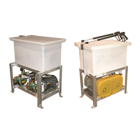
HEUTE ProfilGate Dosing station User manual

ProfilGate® Dosing station
91EN
Operating Manual

Dimensions and views
Min./Max. Water Pressure (bar) 2,0 - 4,5 barWater Intake Pipe 3/4 "ProfilGate®Tray Filling Pipe 1/2 "Max. Water Temp. (°C) 70 °CIP Protection ClassIP 54Power Supply230 V AC 50 HzPower Input (kW)0,1 kWControl Voltage (V)230 VInput Fuse (A)2,5 A mtDimensions (W x H x D mm) 400 x 400 x 200Weight (kg) 10 kgMixing Proportion via Venturi Valve0,3 - 10 %Technical data ProfilGate® aqua Dosing station Art.-Nr. 005-95202
Inlet cleaning/disinfection liquid
Electronic conection 1x230V/N/PE
Water inlet 3/4"
Filling 1/2"
EN

IMPORTANT – READ FIRST Only start up the dosing station and its connections in combination with the ProfilGate® Aqua cleaning field after you have read and understood these operating instructions. These operating instructions contain important information on the installation, use and maintenance of the system. If you have any questions, please do not hesitate to contact us.The ProfilGate dosing station of HEUTE Maschinenfabrik is built and tested according to the current safety regulations. The proper function and operational safety can only be guaranteed if the generally applicable safety precautions and system-specific safety instructions from this operating manual are observed during use. The installation and commissioning of the dosing station may only be carried out by appropriately qualified personnel. As this is electrical equipment, non-observance of the operating instructions and their safety instructions or commissioning, maintenance, repair by unqualified personnel can lead to serious injury or death. The supply and discharge lines of the dosing station must be connected by qualified personnel only. In the event of non-observance, the manufacturer accepts no liability for possible personal injury or damage to property. As the system works with water and cleaning/disinfection media, the operator or his instructed specialist personnel is responsible for the proper use and handling of the media. In the event of damage caused by non-observance of these operating instructions, the warranty will be voided. In case of problems, please contact our service department immediately.Intended useThe dosing station in combination with ProfilGate® Aqua cleaning fields is intended for commercial use when working in hygienic areas such as:•Food processing.•Commercial kitchens.•Rooms with clean room technology.•Pharmaceutical industry.The use is only permitted:•In technically perfect condition.•After correct installation.•In compliance with legal requirements and, if applicable,operational cleaning and maintenance requirements.Please note that additional equipment may only be installed with the consent of the manufacturer. The intended use (type, extent, mixing ratio) of cleaning and/or disinfection media is the sole responsibility of the operator or its qualified personnel.Foreseeable misuse
The dosing station is generally not suitable in the case of:
•Filling of any containers (e.g. basins, aquariums, pools)except ProfilGate® Aqua cleaning fields.•Use of cleaning and/or disinfection media which are notsuitable or whose mixing ratio is not suitable.•Use with the addition of corrosive liquids.3such as short circuit, electric shock, fire, among others. Maintenance and repair may only be carried out by authorized persons using original parts. The operator is responsible for any personal injury and material damage resulting from improper use and operating and/or installation errors.If non-original spare parts are used or if unauthorized modifications are made to the machine, the manufacturer's/marketer's declaration of conformity and the CE mark are immediately invalidated.Always use the machine indoors only.Operation is only permitted at ambient temperatures between 0 °C and 40 °C.Danger to health due to contamination! Failure to observe the hygiene regulations can lead to contamination of the end product and thus to injury and damage to the health of the consumer. Observe all legal requirements and hygiene regulations in your industry. Follow all hygiene-relevant instructions in these operating instructions. Please note that the mixing ratios given in these operating instructions are only approximate. The optimum mixing ratio for the respective application can only be determined by the operator. Ensure that the operating environment of the machine complies with the stated specifications at all times.Operating the machine in the presence of oils, acids, gases, vapors, dusts or radiation may damage the control board.Ensure clean ambient conditions when working on the control cabinet or the circuit board..The control cabinet complies with protection class IP 54. The power supply is 230 V AC 50 Hz.In principle, the specific data on the factory labelof the dosing cabinet are decisive.Always disconnect the power plug before servicing and repair work.Do not continue to use the machine if it is damaged and disconnect the power plug.Depending on the conditions of use, place of use, age and wear of the electrical device, there are different potential dangers for the user. Regular inspection of electrical equipment is intended to ensure maximum safety for the user. Observe the obligation to test electrical equipment.In commercial facilities, observe the industrial safety ordinance and accident prevention regulations as well as other regulations of the associations.Do not use any corrosive or aggressive cleaning agents when cleaning the control cabinet, as these may attack and damage the installed components.The dosing station may only be used in combination with ProfilGate® Aqua cleaning fields by authorized and instructed persons. The dosing station must not be modified or converted, as this may lead to risksSafety instructionsEN

4WelcomeDear customer, thank you for purchasing our HEUTE dosing station. These operating instructions are part of the machine and contain important information on commissioning, operation, maintenance. Please keep this operating manual for future reference!Scope of deliveryDosing station including installed power cable, canister basket, operating instructionsDeclaration of conformityWe hereby declare that the product•Description: Dosing station for ProfilGate® Aquacleaning fields•Type/Model: Dosing station•Serial number: see type plate•Year of manufacture: see type plateAuthorized representative Steffen Moersch, same address as manufacturer. Christian Löwe (Managing Director) HEUTE Maschinenfabrik GmbH & Co. KGEnvironmental protectionDisposal of the transport packagingThe packaging materials of your new machine are environmentally compatible and recyclable. Please help and dispose of the packaging in an environmentally friendly manner.Disposal of the product
Old equipment that is no longer used is not worthless waste. Valuable raw materials can be recovered through environmentally friendly disposal. For information on current disposal methods, please contact the person responsible in your company or your local authority.
Table of contents
Important - read first 2Intended use 2Misuse 3Safety instructions 3Welcome3Scope of delivery 3Declaration of conformity 4Environmental protection 44Technical data4Installation and commissioning 5556778Set up
Connections
CleaningDimensions and viewscomplies with the provisions of the following EU directives:•Machinery Directive 2006/42/EU•Low Voltage Directive 2014/35/EU•Electromagnetic Compatibility (EMC) Directive2014/30/EU•General Product Safety Directive 2001/95/EC•
•Regulation on food contact materials 1935/2004/EGRegulation on good manufacturing practice for food contactmaterials 2023/2006/EG•Regulation on plastic materials and articles intended tocome into contact with foodstuffs (EU) 10/2011Default setting and operationService and maintenanceCircuit diagramin accordance with the following standards and specifications:In the event of a change to the product not agreed with us, this declaration shall lose its validity. •
•
•DIN EN ISO 12100 Safety of machinery - General principles for design - Risk assessment and risk reduction DIN EN 60204-1 VDE0113 Part 1, Electrical equipment of machines - General requirementsDIN EN ISO 13849 Safety of machinery - Safety-related parts of control systems - Part 1: General principles for design•
•
•DIN IS 13850 Safety of machinery - Emergency stop design principlesDIN EN 953 Safety of machinery - Guards - General requirements for the design and construction of fixed and movable guardsDIN EN ISO 13857 Safety of machinery - Safety distances to prevent hazard zones being reached by the upper and lower limbs•DIN EN 349 Safety of machinery - Minimum gaps to avoidcrushing of parts of the human body•DIN EN 614-1 Safety of machinery - Ergonomic designprinciples - Part 1: Terminology and general principles•DIN EN ISO 14159 Safety of machinery - Hygienerequirements for the design of machinery (ISO 14159/2002)•DIN EN 1672-2 Food processing machinery-Generalprinciples for design Part 2 -Hygiene requirementsInstruction time switch9EN

Installation and commissioningSet upThe dosing station is factory-set for fixing to a building wall. The control cabinet should be positioned at a height that allows it to be easily reached. Mount the stainless steel canister basket (for containers up to 10 liters) in a suitable proximity. To use the station with the ProfilGate® Aqua cleaning panels, a water supply is required in addition to a 230 V power supply. Select the positioning and fixing of the dosing cabinet and canister basket depending on the local conditions and spatial proximity to the Aqua cleaning tank using a suitable screw connection.Water connectionsThe supply with fresh water is carried out by means of pipe laying at the 3/4" connection with water pressure 2.0 - 4.5 bar (min./max.), according to Fig. 2. The dosing station does not have an upstream check valve and water filter in the factory. If necessary, an appropriate check valve and water filter must be connected upstream. The water outlet (filling) is made via the 1/2" connection as shown in Fig. 2. This water outlet is connected to the 1/2" sleeve of the Aqua cleaning field - see Fig. 3. Fig. 1ConnectionsFig. 2Fig. 3Liquid supplyThe silicone hose with sieve of the dosing station is inserted into the canister with cleaning/disinfection agent - see Fig.4 (cleaning and disinfection agent not included in the scope of delivery).Fig. 45EN

Make absolutely sure that the required supply voltage matches the voltage provided in your country.Yellow-brown0,3 Electrical connection230 V AC 50 Hz with input fuse 2,5A mt.Fig. 5In automatic mode, the solenoid valve "Water" is switched via the timer at freely selectable time intervals and cleaning/disinfection liquid from the canister is added to the water in an adjustable percentage (1% to 20%) by means of an injector.During initial start-up, immerse the hose end with the strainer attachment of the transparent liquid hose in the cleaning agent canister - see Fig 5. The canister incl. liquid is not included in the scope of delivery. The cleaning/disinfection agent must not contain any chlorine or bleach components, as these could damage the stainless steel surface of the Aqua cleaning tubs.Dosing systemThe detergent/disinfectant is dosed via nozzles with different flow rates - included in the scope of delivery (see Fig. 6). Fig. 6To achieve the desired water/liquid concentration, the appropriate nozzle must be selected - see Venturi injector setting (table below). The information in the table applies exclusively as guide values to facilitate the selection of the nozzle of the desired concentration. In order to set the dosage as accurately as possible, you should carry out tests.Dosing tipcolor
Without tipGreyCrimson BlackYellowBlueGreenWhiteRedBrownTransparentPinkTurquoiseOrange10,08,3 7,15,0 3,8 2,5 2,01,81,5 1,21,0 0,70,60,40,21,210,980,940,90,860,780,70,630,55 0,470,430,40,30,220,2 2,72,22,11,91,81,41,21,00,80,70,60,50,40,3320-110-112-114-120-126-140-149-157-167-185-198-1135-1171-1256-1512-137-145-147-153-157-173-185-198-1128-1142-1160-1197-1248-1366-1640-183-1102-1107-1111-1116-1128-1142-1160-1183-213-1233-1284-1366-1512-1%%%1 cps75 cps200 cpsRatioRatioRatioDefault setting and operationBasically, the system can fill or refill (sharpen) the tubs independently of the timer. This filling is done by means of the rotary switch on the front of the electric box with the timer (see Fig. 5).Setting Venturi injectorChange injectorSwitch off the power to the unit at the control cabinet and close the fresh water supply. Open the control cabinet with the supplied key. Pull the silicone hose off the mixer tap as shown in Fig. 7.Fig. 7*Centipoise (cps) is a measure of the flow resistance of liquids. One cps corresponds to the flow resistance of water. 200 cps corresponds to the flow resistance of motor oil.All injection speeds are based on 2.75 bar connection pressure and a water flow rate of 10 liters/minute.6Remove the existing colored nozzle (rotary thread) see Fig. 8.EN

7The timer can be used, for example, to set the start and end of daily tank filling (e.g. 3 minutes filling at 6.00 a.m. on weekdays). The same applies to the interval of a possible refilling. The exact setting options can be found in the schematic diagram (see p. 9 - 13).Activation of the detergent/disinfectant occurs when water is supplied through the system.Switch on the machine by operating the manual switch ("Filling manual" ) until the liquid to be dosed arrives at the level of the mixing battery system. This can be easily seen through the transparent hose - see Fig. 9 on the left. For optimum function and mixing, cleaning/disinfection media should be used which approximately correspond to the viscosity of water (water = viscosity of 1). Media with a higher viscosity (more viscous) may cause feeding problems.Set timerDe-energize the device at the control box. To adjust the timer to the required conditions, open the electrical box using a suitable screwdriver and continue to open the plastic cover of the timer - see Fig. 9.Fig. 9Fig. 8Select an injector that is optimal for your conditions and operational requirements (different colored reducers) - see Venturi injector. If, for example, no injector is used, this corresponds to a ratio of 10:1 (10 parts fresh water, 1 part liquid), i.e. 10% liquid addition The color green realizes the ratio 49:1 (49 parts fresh water, 1 part liquid), i.e. 2% liquid. Turn the injector in and reinsert the silicone hose as far as it will go. Close the control cabinet, open the fresh water supply and switch the unit back on.Dosing system - rinsingWe recommend flushing the system for the additional liquid on a regular basis. In principle, however, cleaning must be carried out each time the cleaning/disinfectant container is changed and other maintenance work is carried out. To do this, immerse the silicone hose with the attached dirt strainer in a container of clear tap water and let the machine run for 20-30 seconds. Deposits and foreign bodies can cause damage to the system. Therefore, in case of prolonged non-use, check that the silicone hose and the dirt strainer attachment (on the silicone hose) are free of deposits before use. If necessary, rinse the dispensing system with clear tap water. Longer non-useIf you foresee that the machine will not be in use for a longer period of time (e.g. company vacations), please also flush the dosing system as a preventive measure so that no deposits or line blockages can occur in the dosing system.Disconnect the power supply at the control cabinet before carrying out any work on the device.Disconnect the water supply before carrying out any work on the unit.ControlThe dosing station should be checked regularly for its function. Attention should be paid to whether components are damaged or worn and whether the machine guarantees the required cleaning effect. Service Interval
ControlCleaning surface control cabinetCleaning sieve liquid supplyCleaning of mixing system1 x per week1 x per weekafter each change of liquid1 x per month or generally when liquid is changedCircuit diagram see page 8.The intervals at which the dosing station should be cleaned (flushed) depend on the operating circumstances. Shorter cleaning intervals should be selected in the case of a high degree of use.Service and maintenanceService and repairs on the machine should be carried out exclusively by the qualified personnel trained for this purpose. To ensure optimum function, the system must be checked, cleaned and serviced at regular intervals. Our systems are basically low-maintenance and reliable. However, there are components that wear out after a correspondingly long period of use and/or reduce the cleaning quality.CleaningEN

8Circuit diagram

Technical data
4126 31 4126 32 4126 33
047 61 6047 60 047 63
Supply voltage: 230V 50/60Hz 24V AC/DC
Effective power consumption: Approx. 1 W
1 changeover contact 16A 250V~μ cos = 1
600W max. 70μF
~ 0,1 s / day
single strand
1,5...4 mm
multi strand
1,5...2,5 mm
56
5 years
--20°C to +60°C
-20°C to +55°C
Contact rating:
Parallel compensation:
Accuracy:
Terminal capacity:
Programmes:
Battery reserve:
Storage ambient:
Working ambient:
IP: 20
max. 1,4 Nm
General information
•Start-up: after applying the supply voltage, the time switch starts automatically
with the last selected function. The relay position is set by the current program.
•Battery backup
-Backlighting not active
-Data key READ/WRITE only via the menu
!
Safety notes
This product should be installed in line with installation rules, preferably by a qualified electrician. Incorrect installation and use can
lead to risk of electric shock or fire. Before carrying out the installation read the instructions and take account of the product’s
specific mounting location. Do not open up, dismantle, alter or modify the device except where specifical-ly required to do so
by the instructions. All Legrand products must be opened and repaired exclusively by personnel trained and approved by Legrand. Any
unauthorised opening or repair completely cancels all liabilities and the rights to replacement and guarantees. Use only Legrand brand
accessories.
The device contains a LiMnO2 primary cell. When the product reaches the end of its life, this cell must be correctly removed and disposed of
in accordance with national legislation and the requirements of environmental protection.
Time switch
AlphaRex3D21 - 1-channel
4 126 31 / 32 / 33 - 047 61 / 63 / 6047 60 ®
9120V 50/60Hz

2000 W
1000 W
2000 VA 600 W 70 μF
+
c
R
2000 W
+
2000 W 2000 W
+
4000 W
LED
1000 W
00000
421
L
N
max. 250 V AC
L
N
max. 16 A
Overview of programmed switching times for the week.
Resolution 0.5h
Switch status
Day, Time, Date
Function
Supply voltage
Operating principle: Typ 1.B. S. T.
IEC/EN 60730-1, IEC/EN 60730-2-7
Operation in a normal environment
Montage: in distribution panel, Degree of
contamination: 2
Switch output, potential-free
Rated impulse voltage: 4 kV
Select menu, back to main menu, Hold down > 1s = operating display
Confirm selection or load parameters
Select menu options or set parameters
Overview
This symbol indicates that the
selection is active.
* Only vailable in EXPERT mode.
쐉
씈
씉
10
쐅
쐈
Receptacle for data key

쐃 Set language Set time/date, summertime/wintertime
Summertime: ± 1 hour
Europe: Factory set
SPECIAL: The switchover to/from
summertime can be freely programmed by entering a start date and
end date and is then executed each year on the same day of the
week, e.g. Sunday
with a logical OR.
*
*
CHRONO = All switch commands are executed in chronological order in a week INPUT = Programs are
executed in the order in which they are entered
Set MON and TUES as
on/off days
Programming
A program consists of an ON time, OFF time and associated on and off days.
Programs with predefined on/off days (Mon to Sun, Mon to Fri and Sat and Sun): for these programs, you only need to set the switching
times.
With the „INDIVIDUAL” option,
you can allocate switching times to
specific days of your choice.
The programs of a channel are combined 11

Modes
•Auto - Automatic operation
•Constant ON
•Constant OFF
•Extra
The switch status imposed by the program is inverted
(manual override). With the next effective switch
command, the time switch resumes control of on/off
switching.
1 h-Test
When this function is activated, the output is switched on for one hour.
쐂
After one hour, the time switch returns automatically to the programmed
mode.
쐆 Data key
4 128 72/73
or
or
Load the programs of the time switch on to a data key (WRITE KEY) Warning! all programs
stored on the data key will be overwritten.
Load the programs from the data key to the time switch (READ KEY) Warning! all programs
programmed in the time switch will be overwritten. 12Contrast Adjustment

Random function
Function to simulate presence.
Function active: the programmed switching cycles are shifted at random within the range of ± 15 minutes.
쐎
Hour counter
Displays the total relay ON time, (0 to 65535 h) and the date of the last reset.
쐊
Pincode
PIN CODE active: The menus of the time switch will not be accessible unless the PIN CODE has been entered. When the pin code is active,
access to the button and key functions is disabled 1 minute after the last button press.
PIN free access can be re-enabled by selecting PASSIVE or by resetting the device.
쐅
Example
• Power grid synchronisation to improve the accurac
• Cycle functio
• Automatic channel switchin
Note: Upon switching from ACTIVE to PASSIVE the additional menu items are hidden again and all the Expert mode settings are cancelled.
After re-activating, Expert mode will operate again with the basic settings. 13Some additional functions are available in Expert mode:
Expert mode
쐈

쐉 Holiday
After activation the holiday program is executed between 0:00h on the start date and 24:00h on the end date (Constant ON/OFF). After the
holiday program has run once, it must be reactivated.
Activating and deactivating grid synchronisation
Only available in EXPERT mode.
The default setting is PASSIVE. In order to improve the long-term accuracy, it is advisable to activate syn-chronisation if the time switch is
supplied from a on 50/60 Hz grid with frequency adjustment.
씈
Cycle function
Only available in EXPERT mode
For cyclical switch commands the switching on time is set by logical “OR“ of programs of all types. A fixed cycle of ON and OFF time then
operates within those limits. The cycle always starts with the ON time. The cycle duration and the ON time within the cycle are the same
length for all switching times. The cycle duration and the ON time can be set independently in one-second increments. If the switching time is
shor-ter than the cycle duration, the cycle will be shortened accordingly. The ON time will remain unchanged. If the switching time is actually
shorter than the ON time, the ON time will be shortened accordingly.
min max
Period 2s 2h
Pulse 1s 1h 59min 59s 14씉

0:10:00 0:10:00 0:10:00
0:04:00 0:04:00
0:04:00
15:00:00 15:10:00 15:20:00 15:30:00
15:32:00
Program 1
Relais Chanal 1
Program n
1
2
+
Warning: Elektrical shock - Disconnect all power from the device before
dismantling the module and replacing the battery.
Always use a Li cell type battery (LiMnO2) CR2477, 3V high temperature
type min +85 °C
Reset
Warning!
The memory will be cleared, and all
set data will be lost.
Hold down for more than 3 seconds
and at the same time press and release
.
The language, time, date, summertime/ wintertime and
switching times will have to be reentered. 15

04- 2021
This manual contains descriptions of our products, but no guarantees for specific properties or success in use. Unless otherwise agreed, the technical status at the time of the joint delivery of the product and operating manual by HEUTE Maschinenfabrik GmbH & Co. KG. Design and technology are subject to constant further development and improvement. We reserve the right to make technical changes. This manual is protected by copyright. All rights reserved. Copying, reproduction, translation or conversion into any electronic medium or machine-readable form in whole or in part is only permitted with the express written consent of HEUTE Maschinenfabrik GmbH & Co. KG is permitted.EN
Table of contents
Other HEUTE Industrial Equipment manuals
Popular Industrial Equipment manuals by other brands

WATSON INDUSTRIES
WATSON INDUSTRIES AHRS-E304 owner's manual

Martin
Martin M4097 Operator's manual

Festo
Festo EPCO Series operating instructions

Rice Lake
Rice Lake EZ Mount 1 installation guide

Emerson
Emerson Fisher ATST Desuperheater instruction manual

MyBinding
MyBinding GBC VOYAGER Operation & maintenance manual

