Heyer Pasithec User manual
A n e s t h e s i a S y s t e m
Operator’s Manual
Rev. 0.2 Draft – 12/09
I
NNOVATION IN
D
ESIGN AND
T
ECHNOLOGY


H E Y E R P a s i t h e c
Rev. 0.2 Draft – 12/09 HEYER Pasithec, Operator’s manual 3 / 106
Contents
1 Statement .......................................................................................................................................................................... 5
1.1 Manufacturer Responsibility...................................................................................................................................... 5
1.2 Security, Reliability and Operating Conditions........................................................................................................... 5
1.3 Return ...................................................................................................................................................................... 6
1.4 Details of the Manufacturer....................................................................................................................................... 6
2 Introduction........................................................................................................................................................................ 7
2.1 Intended Use............................................................................................................................................................ 7
2.1.1 Range of Use.................................................................................................................................................. 7
2.1.2 Contraindication .............................................................................................................................................. 7
2.2 Symbols.................................................................................................................................................................... 7
2.3 Definition, Abbreviation........................................................................................................................................... 10
3 System Components.........................................................................................................................................................11
3.1 Anesthetic System...................................................................................................................................................11
3.2 Breathing System................................................................................................................................................... 17
3.2.1 Bellows Assembly Ports................................................................................................................................. 18
3.2.2 Ventilating Circulation.................................................................................................................................... 19
3.3 Vaporizer................................................................................................................................................................ 19
3.4 Anesthetic Ventilator............................................................................................................................................... 19
3.4.1 Front Panel.................................................................................................................................................... 20
3.4.2 Keys.............................................................................................................................................................. 20
3.4.3 Indicator ........................................................................................................................................................ 21
3.4.4 Navigator Knob.............................................................................................................................................. 21
3.4.5 Screen Layout............................................................................................................................................... 21
3.4.6 Rear Panel.................................................................................................................................................... 24
3.5 Menu...................................................................................................................................................................... 25
3.5.1 Operating Guide............................................................................................................................................ 25
3.5.2 Menu Diagram............................................................................................................................................... 28
4 Operating Guide .............................................................................................................................................................. 34
4.1 Startup.................................................................................................................................................................... 34
4.1.1 System Self Test............................................................................................................................................ 34
4.1.2 Manual Leak Test .......................................................................................................................................... 36
4.1.3 Safety Valve Test........................................................................................................................................... 37
4.1.4 Automatic Leak Test...................................................................................................................................... 38
4.1.5 Compliance Test............................................................................................................................................ 39
4.1.6 Ventilation Mode Setup.................................................................................................................................. 41
4.1.7 Breathing Parameters Setup.......................................................................................................................... 41
4.2 Start Mechanical Ventilation.................................................................................................................................... 41
4.2.1 Stop Mechanical Ventilation........................................................................................................................... 41
4.3 Start Manual Ventilation.......................................................................................................................................... 42
4.3.1 Stop Manual Ventilation................................................................................................................................. 42
4.4 Shutdown ............................................................................................................................................................... 42
4.5 Waveforms ............................................................................................................................................................. 42
5 Pre-use Check List........................................................................................................................................................... 45
5.1 Pre-use Check List Procedure................................................................................................................................ 45
5.1.1 Check System............................................................................................................................................... 45
5.1.2 Main Failure Alarm Test................................................................................................................................. 46
5.2 Test Gas Supply Pipeline........................................................................................................................................ 46
5.3 Monitoring Flow Control.......................................................................................................................................... 46
5.3.1 Monitoring without Oxygen ............................................................................................................................ 46
5.3.2 Monitoring with Oxygen................................................................................................................................. 48
5.4 Installing and Testing Vaporizer............................................................................................................................... 49
5.4.1 Installation..................................................................................................................................................... 49
5.4.2 Testing Vaporizer........................................................................................................................................... 49
5.5 Alarm Test .............................................................................................................................................................. 50
5.6 Breathing System Test............................................................................................................................................ 51
5.6.1 Check O
2
+ Button.......................................................................................................................................... 51
5.7 Ventilator Test......................................................................................................................................................... 51
6 Installation and Connection.............................................................................................................................................. 53
6.1 Install the Absorber Canister................................................................................................................................... 54
6.1.1 When to Replace Absorbent.......................................................................................................................... 54
6.1.2 Disassembling Absorber................................................................................................................................ 55
6.1.3 Filling Absorbent............................................................................................................................................ 55
6.2 Connecting Tubes and Lines................................................................................................................................... 55
6.2.1 Connect CO
2
Monitor..................................................................................................................................... 56
6.2.2 Connect Anesthetic Agent Monitor................................................................................................................. 57
6.3 Connecting Gas and Electricity............................................................................................................................... 57
6.3.1 AC Inlet......................................................................................................................................................... 58
6.3.2 Aux. Mains Outlet.......................................................................................................................................... 58
6.3.3 Communication Port...................................................................................................................................... 59
6.3.4 Gas Inlet Module........................................................................................................................................... 59
7 Cleaning and Disinfecting ................................................................................................................................................ 60

HEYER Pasithec
4 / 106 HEYER Pasithec, Operator’s manual Rev. 0.2 Draft - 12/09
7.1 Cleaning and Disinfecting prior to first Use ............................................................................................................. 60
7.2 Cleanable Breathing System Components.............................................................................................................. 61
7.3 Absorber Circle....................................................................................................................................................... 61
7.3.1 Disassembling Absorber Circle...................................................................................................................... 62
7.3.2 Bellows Assembly.......................................................................................................................................... 64
7.3.3 Regular Maintenance .................................................................................................................................... 68
8 User Maintenance............................................................................................................................................................ 69
8.1 Repair Policy .......................................................................................................................................................... 69
8.2 Maintaining Outline and Schedule........................................................................................................................... 69
8.2.1 User Maintenance ......................................................................................................................................... 70
8.2.2 Useful Life Estimation.................................................................................................................................... 70
8.2.3 Replacement of Consumable Parts ............................................................................................................... 70
8.3 Maintaining the Breathing System........................................................................................................................... 70
8.3.1 Replace O
2
Sensor........................................................................................................................................ 71
8.3.2 Calibrate O
2
Sensor....................................................................................................................................... 71
8.3.3 Calibrate CO
2
Sensor.................................................................................................................................... 74
8.3.4 Calibrate Agents............................................................................................................................................ 76
8.4 Maintaining O
2
Sensor............................................................................................................................................ 77
8.5 Replace the Fuses.................................................................................................................................................. 78
8.6 Maintaining Battery................................................................................................................................................. 78
8.7 The IRMAProbe..................................................................................................................................................... 79
9 Alarm and Troubleshooting.............................................................................................................................................. 80
9.1 About Alarm............................................................................................................................................................ 80
9.2 Alarm Message List................................................................................................................................................ 80
9.2.1 TechnicalAlarm............................................................................................................................................. 81
9.2.2 FunctionalAlarm............................................................................................................................................ 83
9.3 Troubleshooting...................................................................................................................................................... 86
10 Specifications and Operation Theory........................................................................................................................... 87
10.1 Physical Specification............................................................................................................................................. 87
10.2 Environment Requirements..................................................................................................................................... 87
10.3 System’s Technical Specifications........................................................................................................................... 88
10.3.1 Gas Supply.................................................................................................................................................... 88
10.3.2 Flowmeter ..................................................................................................................................................... 88
10.3.3 Classification................................................................................................................................................. 88
10.4 Input/Output............................................................................................................................................................ 89
10.4.1 Electrical........................................................................................................................................................ 89
10.4.2 Pneumatic..................................................................................................................................................... 89
10.5 Electromagnetic Compatibility................................................................................................................................. 89
10.6 Operation Theory.................................................................................................................................................... 90
10.6.1 Pneumatic System......................................................................................................................................... 91
10.7 Breathing System Technical Specification............................................................................................................... 92
10.8 Anesthetic Ventilator Specifications......................................................................................................................... 92
10.8.1 Ventilator Performance.................................................................................................................................. 92
10.8.2 Ventilation Mode Settings.............................................................................................................................. 93
10.8.3 Ventilating Parameters Settings..................................................................................................................... 93
10.8.4 Gas Dynamics Performance.......................................................................................................................... 93
10.8.5 Setting Alarm Parameters.............................................................................................................................. 94
10.8.6 Monitoring Performance ................................................................................................................................ 95
10.9 O
2
Monitoring Specification..................................................................................................................................... 96
10.10 IRMA Probe Specification................................................................................................................................... 96
10.10.1 Intended Use............................................................................................................................................ 96
10.10.2 Technical Specification.............................................................................................................................. 97
10.10.3 System Assembly Instruction .................................................................................................................... 99
10.10.4 Zeroing Procedure.................................................................................................................................. 100
10.10.5 Alarms.................................................................................................................................................... 101
10.10.6 Cleaning ................................................................................................................................................. 101
10.10.7 Preventive Maintenance Instructions....................................................................................................... 101
10.10.8 Warnings ................................................................................................................................................ 101
10.10.9 Cautions................................................................................................................................................. 101
11 Warranty ................................................................................................................................................................... 102

H E Y E R P a s i t h e c
Rev. 0.2 Draft – 12/09 HEYER Pasithec, Operator’s manual 5 / 106
1 Statement
HEYER Medical AG (“HEYER”) holds the copyright to this manual, which is not publicly published, and
reserves the right to maintain it as a secure document. Refer to this manual when operating,
maintaining and repairing products only. Releasing information contained within the manual is
prohibited.
Proprietary materials protected by copyright law are included in this manual. No section of it can be
reproduced, copied, or translated into other languages without prior written approval from HEYER.
All instructions in this manual are considered to be correct. HEYER is not legally responsible for
damages caused by incorrect installation or operation. HEYER does not supply privileges endowed by
patent law to any other parties. HEYER is not legally responsible for the consequences of breaking the
patent law or of a third party violation.
Refer to this manual before using the product. The manual includes: Operating procedures which must
be performed with caution; information on actions and situations that may result in damage to the
equipment, and actions and situations that may cause bodily harm. HEYER is not responsible for the
security, reliability, and/or function of the equipment in the event that damage or other irregular actions
occur. Repairs for these malfunctions are not covered by the warranty.
HEYER has the rights to replace any content in this manual without notice.
1.1 Manufacturer Responsibility
HEYER is responsible for the security, reliability, and function of the equipment when the following
conditions are adhered to:
Installation, adjustments, and repairs must be performed by individuals authorized by HEYER;
Necessary electrical equipment and the working environment must be in accordance with national
and professional standards and the requirements listed in this manual;
Equipment must be used as stated in the operating instructions.
CAUTION: This equipment is not for family use.
CAUTION: Malfunctioning equipment may cause damage and/or bodily injury if repair
request are not submitted in a timely manner by the company or organization
using the equipment.
The paid theoretical framework diagram, calibrating method, and other instructions will be supplied to
the customer upon request. With the assistance of qualified technicians and when stipulated by
HEYER, specific equipment parts can be repaired by the customer.
1.2 Security, Reliability and Operating Conditions
HEYER is not responsible for the security, reliability and operating conditions of this product when:
The assemblies are disassembled, extended, or readjusted
The product is not operated correctly in accordance with the manual instructions; the power
supply that is used is incorrect, and/or the product is operated in an environment other than
optimal conditions per this manual.

HEYER Pasithec
6 / 106 HEYER Pasithec, Operator’s manual Rev. 0.2 Draft - 12/09
1.3 Return
In the event a product needs to be returned to HEYER, please follow these steps:
1. Obtain the right of return.
Contact our customer service department with the product number and type. The number is
marked on the surface of the product and is required for a return. Enclose a letter containing
the product number, type, and the reason for the return.
2. Transportation charges
Transportation and insurance charges must be prepaid by the user prior to shipping the
product to HEYER for repair.
1.4 Details of the Manufacturer
Apparatus: Anesthesia System HEYER Pasithec
Manufacturer: HEYER Medical AG
Carl-HEYER-Strasse 1-3
D-56130 Bad Ems / Germany
Tel.: +49 (0) 2603 / 791-3
Fax: +49 (0) 2603 / 70424
E-Mail: info@heyermedical.de
Internet: http://www.heyermedical.de

H E Y E R P a s i t h e c
Rev. 0.2 Draft – 12/09 HEYER Pasithec, Operator’s manual 7 / 106
2 Introduction
2.1 Intended Use
The HEYER Pasithec is a compact and integrated anesthesia transmitting system. The anesthetic
ventilator not only provides patients undergoing operations with auto ventilation, but also monitors and
displays the patient’s various parameters.
The anesthetic ventilator used in the system is controlled by a microprocessor, which internally
configures the monitor and the volume mode; other functions are optional.
Not all the optional functions available may be included in the manual. It is also possible to add other
equipment to the top or middle of this system for added functions. For more information with respect to
the existing product, please contact your local representatives.
WARNING: All Pasithec users must be trained.
WARNING: HEYER Pasithec is not suitable for use in an MRI environment.
2.1.1 Range of Use
Pasithec is applicable for patients of over 2 kg with standard configuration. Pasithec is for use in the
Operating Room and/or Emergency Room of a hospital, drug addiction treatment center, or other
medical facilities where anesthesia is used.
2.1.2 Contraindication
Pasithec is not suitable for pneumothorax patients
2.2 Symbols
Warnings and Cautions indicate all the possible dangers in case of violation of the
stipulations in this manual. Refer to and follow them.
WARNING: Indicates potential hazards to operators or patients.
CAUTION: Indicates potential damage to equipment.
HEYER Pasithec
8 / 106 HEYER Pasithec, Operator’s manual Rev. 0.2 Draft - 12/09
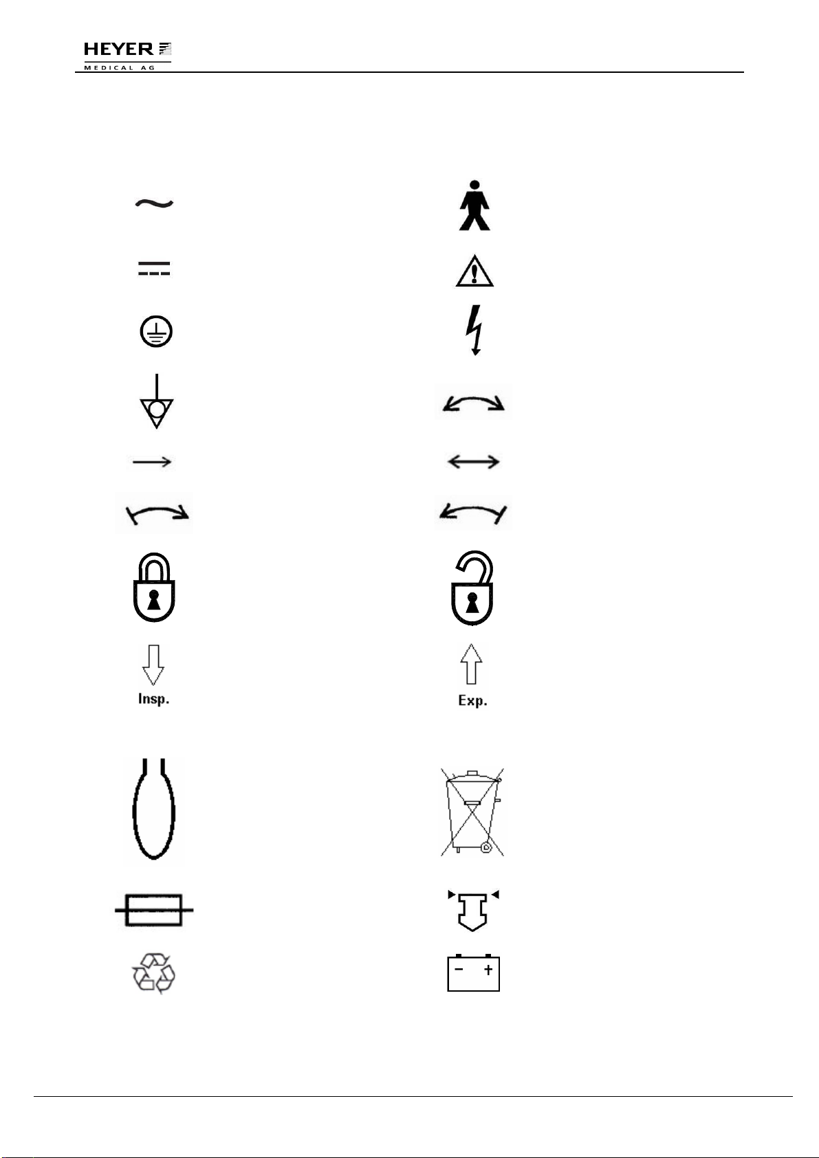
Instead of illustrations, other symbols may also be utilized. Not all of them may necessarily appear in
the equipment and manual. The symbols include:
AC: Alternating current
Type B Applied Part
DC: Direct current
Attention: consult
accompanying document
Protective earth Dangerous Voltage
Equipotentiality Rotation in two directions
Movement in one direction Movement in two directions
Right-turning movement Left-turning movement
Lock
Unlock
Inspiration flow
Expiration flow
SN Serial Number O
2
+ O
2
flush
Reservoir bag port
Do not dispose in garbage
basket.
Fuse
View the reading on the top
of the float.
Recyclable Battery

H E Y E R P a s i t h e c
Rev. 0.2 Draft – 12/09 HEYER Pasithec, Operator’s manual 9 / 106
Bell cancel Variability of rotational
adjustment
Bell
Non-ionizing
electromagnetic radiation
△! Alarm, general Date of manufacture
△!! Urgent alarm Address of manufacturer
EC Representative
0
00
0
PENDING
The system, with this label
under the stipulations in the
operating manual, complies
with the requirements
related from 93/42/EEC.

HEYER Pasithec
10 / 106 HEYER Pasithec, Operator’s manual Rev. 0.2 Draft - 12/09
2.3 Definition, Abbreviation
AC135 Anesthetic Breathing System
AGSS Anesthetic Gas Scavenging Transfer & Receiving System
APL Adjustable Pressure Limit
BDU Basic Data Unit
C Compliance
C·G·O Common Gas Outlet
cmH
2
O Centimeters of Water
IPPV Intermittent Positive Pressure Ventilation
EEPROM Electrically Erasable Programmable Read Only Memory
FiO
2
Fraction of Inspired Oxygen
Flow-t Flow-time Waveform
Freq Frequency
Freq
MIN
Minimum Frequency in PS Mode
GUI Graphical User Interface
I:E Inspiratory to Expiratory Ratio
L Liter
L/min Liters Per Minute
Manual Manual ventilation
ml Milliliter
MRI Magnetic Resonance Imaging
MV Minute Volume
Paw Airway Pressure
Pb Plumbum
PEAK Peak Pressure
PLAT Plat Pressure
MEAN Mean Pressure
Paw-t Pressure-time Waveform
PCV Pressure Control Ventilation
PEEP Positive End Expiratory Pressure
PIP Peak Inspiratory Pressure
PS Pressure Support Ventilation
P
TARGET
Target Pressure
SIMV Synchronized Intermittent Mandatory Ventilation
T
INSP
Inspiratory Time
T
P
Inspiratory Pause Time
Trigger Flow Trigger
T
SLOPE
Inspiratory Slope Time
UI User Interface
V
T
Tidal Volume
WDT Watch Dog Timer
∆P Differential Pressure
Enf. Enflurane
Hal. Halothane
Iso. Isoflurane
Sev. Sevoflurane
Des. Desflurane
ETCO
2
End-Expiratory CO
2
Concentration
INSCO
2
Inspiratory CO
2
Concentration
MAC Minimum Alveolar Concentration

H E Y E R P a s i t h e c
Rev. 0.2 Draft – 12/09 HEYER Pasithec, Operator’s manual 11 / 106
3 System Components
3.1 Anesthetic System
CAUTION: The anesthetic system is intended to be used with the following monitoring
devices, alarm systems, and protection devices:
+ pressure measuring in accordance with 8.1 of ISO 8835-2;
+ system is to be equipped with an ANESTHETIC GAS SCAVENGING
TRANSFER and RECEIVING SYSTEM complying with ISO 8835-3 before
being put into service.
+ pressure limitation device in accordance with 51.101.1 of IEC60601-2-13;
+ exhaled volume monitor in accordance with 51.101.4 of IEC60601-2-13;
+ breathing system integrity alarm system in accordance with 51.101.5 of
IEC60601-2-13;
+ continuing pressure alarm in accordance with 51.101.6 of IEC60601-2-
13;
+ O
2
monitor in accordance with ISO 21647.
+ CO
2
monitor in accordance with ISO 21647.
+ ANESTHETIC monitor in accordance with ISO 21647.
WARNING: To avoid explosion hazards, flammable anesthetic agents such as Ether and
Cyclopropane shall not be used in the anesthetic workstation. Only use
anesthetic agents that comply with the requirements for non-flammable
anesthetic agents as specified in this manual. Halothane, Desflurane,
Sevoflurane, Enflurane, and Isoflurane have been found to be non-
flammable agents.
WARNING: Independent means of ventilation (e.g. a self-inflating manually powered
resuscitator with mask) should be available whenever the anesthetic system
is in use.
WARNING: Do not use antistatic or electrically-conductive breathing tubes and mask.
WARNING: Contact with a liquid, such as anesthetic agent, results in damage within the
device.
WARNING: The incline angle should not exceed 10 degrees whenever the anesthetic
system is in use.
HEYER Pasithec
12 / 106 HEYER Pasithec, Operator’s manual Rev. 0.2 Draft - 12/09
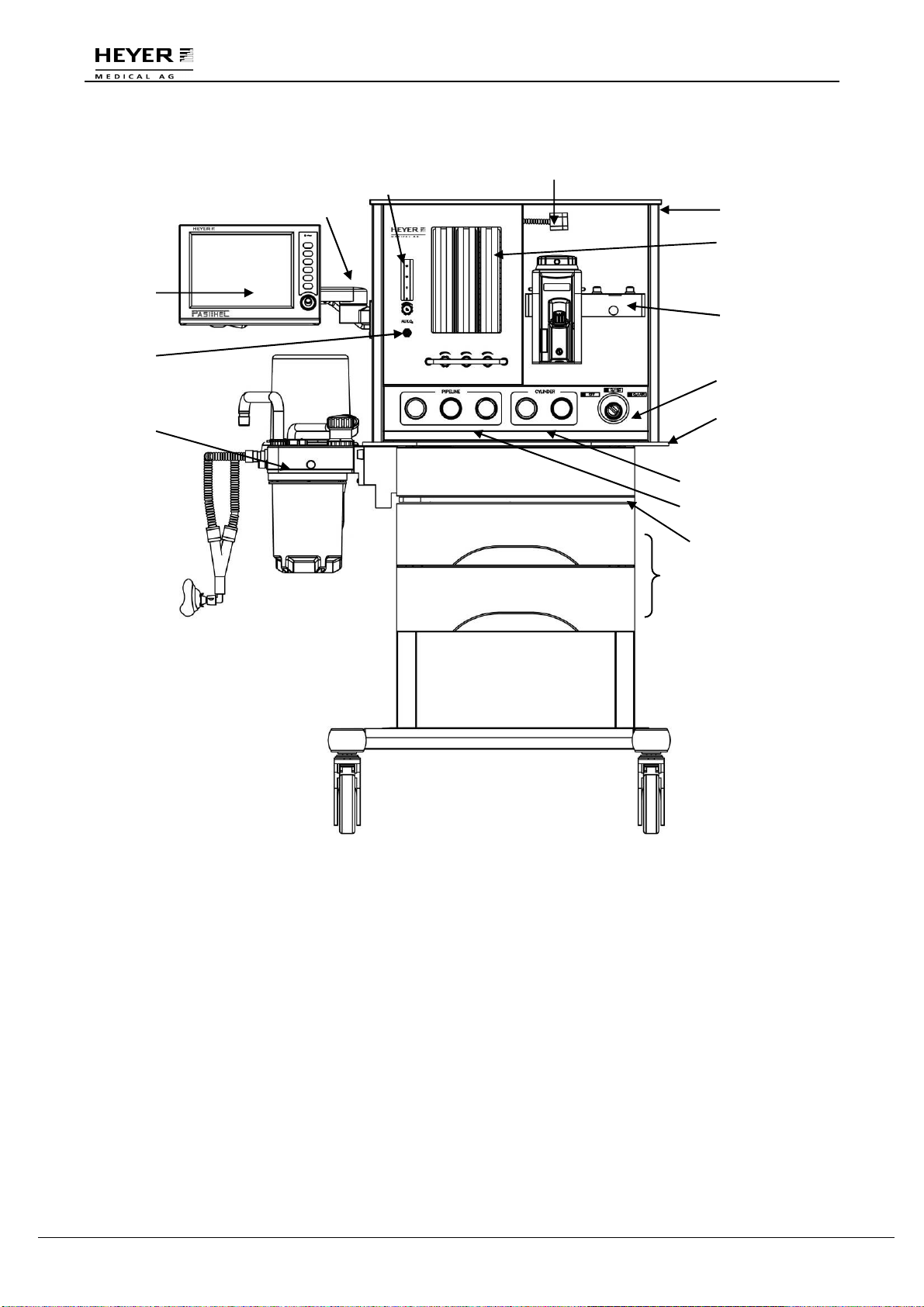
Figure 3-1 Front View
Legend:
1 User Interface (UI) 2 Arm
3 Aux. O
2
Flowmeter 4 Aux. O
2
Outlet
5 Breathing System 6 Flexible Top Light
7 Top Board 8 Flowmeter
9 Vaporizer Mount 10 Pneumatic and Electronic Switch
11 Main tray 12 Cylinder Pressure Gauges
13 Pipeline Pressure Gauges 14 Pull-out Writing Board
15 Drawers
1
2 3
4
5
7
8
9
10
11
12
13
15
6
14

H E Y E R P a s i t h e c
Rev. 0.2 Draft – 12/09 HEYER Pasithec, Operator’s manual 13 / 106
Descriptions of each control function at the front of Pasithec:
Item Description
3 Aux. O
2
Flowmeter Provides O
2
with a maximal flow of 15 L/min to Aux. O
2
.
8 Flowmeter with Flow
Control Knobs Turn the knob counterclockwise to increase the flow; turn
clockwise to decrease the flow.
Reading point is top of float inside flow tube.
6 Top Light The top light will illuminate if top light is switched on. The top light
switch has two settings: on and off.
10 Pneumatic and
Electronic Switch The switch can control electricity and gas and has three settings.
Electricity main switch: OFF, ON, ON; gas way main switch: OFF,
O
2
+N
2
O, O
2
+Air.
Function of electricity main switch: When system is shut off, the
assistant power and controller are started with the main switch.
The machine performs a system self test, and after the test, the
startup is complete. While system is in startup state, turn off the
main switch and be sure the main unit system is closed
completely.
Function of gas way main switch: when switch is in the OFF
position, O
2
, N
2
O and AIR cannot enter the flowmeter. When
switch is in O
2
+N
2
O position, O
2
and N
2
O can enter into flowmeter.
When the switch is in O
2
+Air position, O
2
and AIR can enter.
14 Writing Board The writing board can hold up to 10 kg and can be used by a
doctor during an anesthesia operation.
WARNING: When performing closed or semi-closed ventilation with breathing system,
the Fresh gas switch should be placed to Circle Absorber. Otherwise, there
will be anesthetic gas leakage and abnormal operation of the machine.
HEYER Pasithec
14 / 106 HEYER Pasithec, Operator’s manual Rev. 0.2 Draft - 12/09
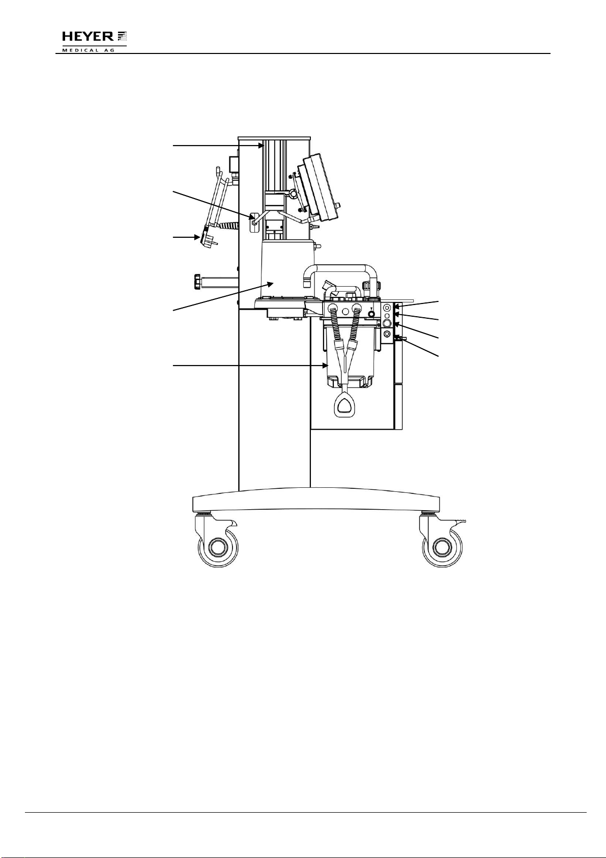
Figure 3-2 Side view
Legend:
16 GCX Mounting Rail 17 UI Signal Cable
18 Power Cable 19 Bellows Assembly
20 Absorber Circle Assembly 21 O
2
Flush (O
2
+)
22 O
2
Sensor Socket 23 Driving Gas Outlet – Switch
24 Driving Gas Outlet (CGO)
20
19
18
21
22
23
24
17
16

H E Y E R P a s i t h e c
Rev. 0.2 Draft – 12/09 HEYER Pasithec, Operator’s manual 15 / 106
Descriptions of each control function at the side view of Pasithec:
Item Description
21 O
2
Flush (O
2
+) Press the O
2
Flush (O
2
+) button to supply the breathing
system with O
2
at a high flow rate.
22 O
2
Sensor Socket Socket to connect Oxygen Sensor for monitoring oxygen
concentration of absorber circle. When monitoring patient
oxygen concentration in inspiratory gas at the back of
inspiratory valve, the socket can be selected.
23 / 24 Driving Gas Outlet (Switch) Provide driving gas to other equipment. Pressure: 280
kPa~600 kPa, flow: max. 90 L/min.

HEYER Pasithec
16 / 106 HEYER Pasithec, Operator’s manual Rev. 0.2 Draft - 12/09
Figure 3-3 Rear View
Legend:
25 Fuses 26 Aux. Power Sockets
27 Power Cable 28 Pipeline Gas Inlet Module
29 Gas Cylinder Yokes
29
25 26 27 28
H E Y E R P a s i t h e c
Rev. 0.2 Draft – 12/09 HEYER Pasithec, Operator’s manual 17 / 106
3.2 Breathing System
CAUTION: The breathing system used together with the anesthetic gas supply system
shall be in accordance with ISO 8835-2.
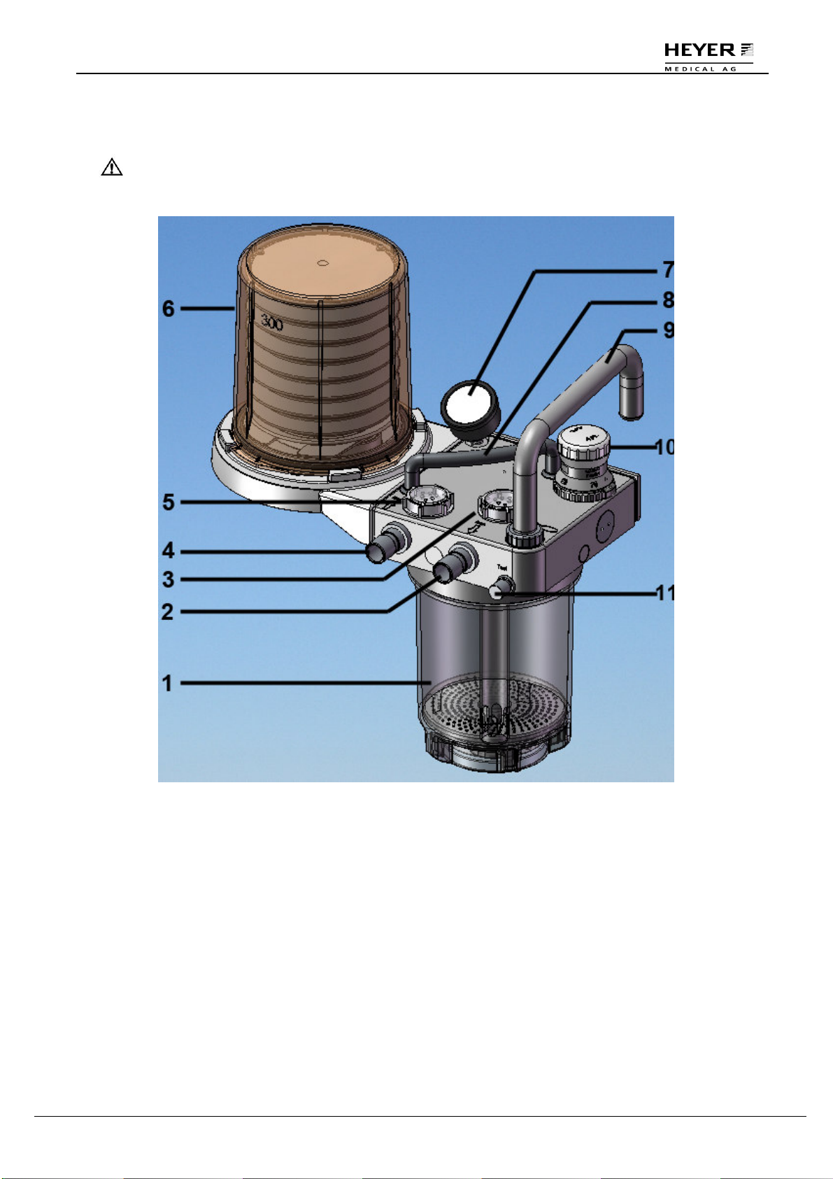
Figure 3-4 Breathing System
Legend:
1 Absorber Canister 2 Inspiratory Port
3 Inspiratory Valve 4 Expiratory Port
5 Expiratory Valve 6 Bellows
7 Airway Pressure Gauge 8 Handle
9 Bag Arm 10 APL valve
11 Test Block

HEYER Pasithec
18 / 106 HEYER Pasithec, Operator’s manual Rev. 0.2 Draft - 12/09
3.2.1 Bellows Assembly Ports
Figure 3-5 Ports of bellows assembly
12 Exhaust Gas Port
13 Nut (drain plug): Loosen the nut to drain the water when absorbent (natrium lime)
in absorber has been commixed with water.
WARNING: Never connect exhaust gas port with sub-atmospheric system directly, as it
results breathing system leakage.
Do not block exhaust gas port.
H E Y E R P a s i t h e c
Rev. 0.2 Draft – 12/09 HEYER Pasithec, Operator’s manual 19 / 106
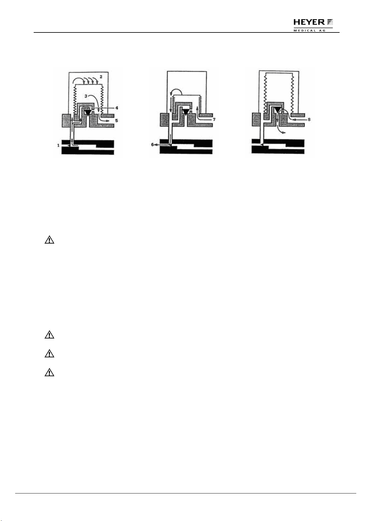
3.2.2 Ventilating Circulation
Inhalation Primary Phase:
1 Exhalation Valve
2 Driving Gas
3 Gas of Patient Circuit
4 Pressure-Relief Valve
5 To Patient Circuit
Exhalation Primary Phase:
6 Driving Gas
7 From Patient Circuit
Exhalation End Phase:
8 Excess Gas from Patient
Circuit
3.3 Vaporizer
CAUTION: The vaporizer used with the anesthetic system shall comply with ISO
8835-4.
A checklist for the assembly of the anesthetic system
from individual components
shall be
provided by the assembler of the anesthetic system.
For more detailed information about the vaporizer, please refer to the instructions for the vaporizer
when used in the anesthetic system.
3.4 Anesthetic Ventilator
CAUTION: Anesthetic ventilator used in anesthetic system shall comply with ISO 8835-
5.
CAUTION: Monitoring conditions of this system: Ambient temperature: 25°C; Air
temperature: 25°C; Air humidity: 30%; Gas component : O
2
.
CAUTION: If the temperature of O
2
sensor is lower than dew point of breathing gas,
vapor may coagulate on the surface of the sensor and oxygen
concentration on the monitor may be lower than the practice value.
HEYER Pasithec
20 / 106 HEYER Pasithec, Operator’s manual Rev. 0.2 Draft - 12/09
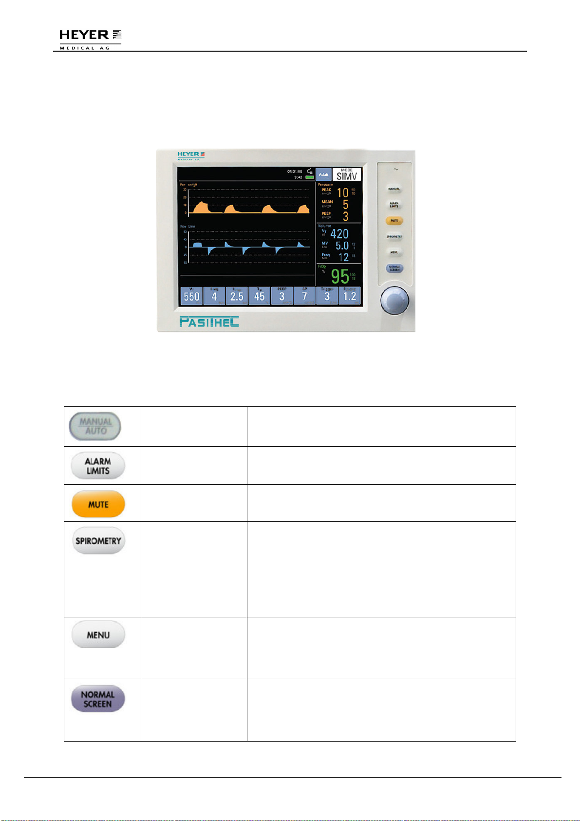
3.4.1 Front Panel
Front panel consists of display screen, keys, indicators, and a knob.
Figure 3-6 Front Panel
3.4.2 Keys
Manual Key Press the key to change original ventilation mode to manual
mode; Press again to change back to the original ventilation
mode.
Alarm Limits Key Press the key to open alarm window on the screen; Press
again to close the alarm window.
MUTE Key Press the key to mute the alarm for 110 seconds. New
alarms shall override the mute.
Spirometry Key This key shall toggle the display between the waveform
window and the two loop display configurations of the
Spirometry Loop Window described in section 4.5. The first
key press shall display the “Pressure-Volume” loop display
configuration. The second key press shall display the “Flow-
Volume” loop display configuration. After both
configurations have been cycled through the display, a third
key press shall return the display to the Normal Screen.
MENU Key Press the key and a “Menu” window appeared on the
display screen; for more details refer to section 3.5.
The first menu key press after the initial power up will
display the calibrate menu, with “Start Calibration”
highlighted.
Normal screen Key The key closes the “Spirometry” and other windows and
returns the screen to pressure and flow waveforms.
If the “Spirometry” and all other windows are already closed
when the NORMAL SCREEN key is pressed again, no
action shall occur.
Table of contents
Other Heyer Medical Equipment manuals


