Heyer Narkomat + User manual

HEYER Narkomat
+
Anesthesia System
Service Manual
Rev.2.1.0
Software version Service software: 1.8.3

2
HEYER MEDICAL AG
Carl-HEYER-Strasse 1-3
56130 Bad Ems
Germany
Tel. +49 - 2603 – 791 - 3
Fax. +49 - 2603 – 791 - 209
E-mail: info@HEYERmedical.de

Table of Contents
3
0 Table of Contents
0Table of Contents ............................................................................................... 3
0.1
Table of Figures........................................................................................................................ 6
1General Information............................................................................................ 7
1.1
Guidelines ................................................................................................................................. 7
1.2
Product improvements.............................................................................................................. 7
1.3
Manufacturer’s Liability ............................................................................................................. 7
1.4
Manufacturer’s specification ..................................................................................................... 8
1.5
Updating status ......................................................................................................................... 8
1.6
Warning, Precautions and Notes .............................................................................................. 9
1.6.1
WARNINGS....................................................................................................................... 9
1.6.2
PRECAUTIONS............................................................................................................... 10
1.6.3
NOTES............................................................................................................................. 11
2Theory of Operation ......................................................................................... 13
2.1
Microprocessor-Controlled Ventilator...................................................................................... 13
2.2
Patient Module........................................................................................................................ 13
2.3
Gas Conditioning Unit............................................................................................................. 13
2.4
The Ventilator Unit .................................................................................................................. 13
2.5
Adjustable Alarms................................................................................................................... 13
2.5.1
P
max
limiting on alarm violation......................................................................................... 14
2.6
Fresh Gas Decoupling ............................................................................................................ 14
2.7
Compliance Compensation..................................................................................................... 14
2.8
Electrical supply...................................................................................................................... 15
2.8.1
Electrical components...................................................................................................... 16
2.9
Power supply module.............................................................................................................. 17
2.9.1
Connectors on power supply board AVM 2-1.................................................................. 18
2.9.2
Fuses on power supply board AVM 2-1........................................................................... 19
2.9.3
Charging / discharging control for the battery:................................................................. 20
2.9.4
Status Indicators Of Battery Control:...............................................................................20
2.10
Module 1.............................................................................................................................. 21
2.10.1
Connectors on module 1.............................................................................................. 22
2.11
Ventilator Module 2, AVM 3-1 and AVM 3-2 ....................................................................... 23
2.11.1
Parts list module 2........................................................................................................ 24
2.11.2
Connectors on module 2.............................................................................................. 24
2.11.2.1
Plug connectors on board AVM 3-1 ........................................................................ 24
2.11.2.2
Plug connectors on board AVM3-2 ......................................................................... 25
2.12
Display................................................................................................................................. 25
2.13
Battery ................................................................................................................................. 25
2.14
Ventilator pneumatic............................................................................................................ 26
2.14.1
Ventilator pneumatic drive............................................................................................ 27
2.14.2
HP pressure reducer.................................................................................................... 27
2.14.3
LP- double stage pressure reducer.............................................................................. 27
2.14.4
Solenoid valves MV1 to MV4....................................................................................... 27
2.14.5
Pneumatic driving module............................................................................................ 28
2.14.6
Flow metering module.................................................................................................. 28
2.14.7
Tube color coding......................................................................................................... 28
2.15
The patient module (circle system) ..................................................................................... 29
2.15.1
Top and back side view on the patient module............................................................ 29
2.15.2
Bottom and back side view on the patient module....................................................... 30
2.15.3
Functional representations of the patient module........................................................ 31
2.15.3.1
CMV mode, inspiration............................................................................................ 32
2.15.3.2
CMV mode, expiration............................................................................................. 33
2.15.3.3
Manual mode, inspiration ........................................................................................ 34
2.15.3.4
Manual mode, expiration......................................................................................... 35
2.15.3.5
Spontaneous mode, inspiration............................................................................... 36
2.15.3.6
Spontaneous mode, expiration................................................................................ 37
2.15.4
Components of the patient module.............................................................................. 38
2.15.4.1
Ventilation bellows system ...................................................................................... 38
2.15.4.2
Manual Respiration Bag / Reservoir........................................................................ 38

Table of Contents
4
2.15.4.3
CO
2
absorber........................................................................................................... 38
2.15.4.4
Inspiratory and expiratory valves............................................................................. 38
2.15.4.5
Airway pressure relief valve .................................................................................... 38
2.15.4.6
Room Air valve........................................................................................................ 38
2.15.4.7
Diaphragm valves.................................................................................................... 38
2.15.2.7.1
Status of the diaphragm valves:....................................................................... 39
2.15.2.7.2
Machine OFF or Ventilator in Standby............................................................. 39
2.15.2.7.3
Manual / Spontaneous Mode, INSPIRATION And EXPIRATION.................... 39
2.15.2.7.4
CMV Child / Adult Mode, INSPIRATION.......................................................... 39
2.15.2.7.5
CMV Child / Adult, EXPIRATION..................................................................... 39
2.15.2.7.6
CMV Adult, EXPIRATION And PEEP .............................................................. 39
2.15.2.7.7
Compliance Test Patient Module ..................................................................... 40
2.15.2.7.8
Leak Test Patient Module and Fresh Gas Module........................................... 40
3Repair Information............................................................................................ 41
3.1
Introduction ............................................................................................................................. 41
3.2
Warnings and precautions ...................................................................................................... 41
3.2.1
Precautions...................................................................................................................... 41
3.2.2
Warnings.......................................................................................................................... 41
3.3
Troubleshooting Guidelines .................................................................................................... 42
3.4
Troubleshooting Charts........................................................................................................... 42
3.4.1
Error Messages during ventilation................................................................................... 42
3.4.2
Alarm messages during the compliance test, leak test and O2 calibration..................... 46
3.4.2.1
Messages during the system tests........................................................................... 47
3.4.2.2
Symptoms of Fuse Failures...................................................................................... 49
3.5
Required Tools........................................................................................................................ 50
3.6
Disassembly instructions......................................................................................................... 50
3.6.1
Connecting and disconnecting vaporizers....................................................................... 50
3.6.2
Removing the compressed gas tanks (PIN-Index).......................................................... 50
3.6.3
Removing the Patient Module..........................................................................................51
3.6.4
Removing the CO
2
Absorber Canister............................................................................. 51
3.6.5
Removing the Bellows and Dome System ......................................................................51
3.6.6
Removing the Airway Pressure Limiting Valve (APL)...................................................... 51
3.6.7
Inspecting/replacing the Decoupling, Bellow and Expiratory Valves............................... 52
3.6.8
Disassembling the Room Air, Inspiration and expiration valves...................................... 52
3.6.9
Removing the Gas Block Module .................................................................................... 52
3.6.10
Removing the flow tubes.............................................................................................. 52
3.6.11
Removing the pressure gauges ................................................................................... 53
3.6.12
Removing the Module 2 Circuit Board Set................................................................... 53
3.6.13
Removing Module1 Circuit Board Set..........................................................................53
3.6.14
Removing the Power Supply Module...........................................................................53
3.6.15
Removing Internal Regulators, Proportional Valve and Flow Divider.......................... 54
4Maintenance and Calibration........................................................................... 55
4.1
Introduction ............................................................................................................................. 55
4.2
Calibration Warnings and Precautions.................................................................................... 55
4.3
Test Procedure........................................................................................................................ 56
4.3.1
General ............................................................................................................................ 56
4.3.2
Inspecting/replacing consumable parts ........................................................................... 56
4.3.3
Power supply checks....................................................................................................... 61
4.3.4
Functional Tests............................................................................................................... 62
4.3.4.1
Pneumatic tests........................................................................................................ 62
4.3.4.2
Alarm Tests............................................................................................................... 63
4.3.4.3
Electrical Tests ......................................................................................................... 65
5Service Software............................................................................................... 66
5.1
Identity Check ......................................................................................................................... 67
5.2
Main Menu .............................................................................................................................. 68
5.3
Set Date and Time.................................................................................................................. 69
5.4
Choose Service....................................................................................................................... 70
5.5
Calibration Routines................................................................................................................ 71
5.5.1
O2Sensor ADC Calibration* ........................................................................................... 72
5.5.2
Pressure Sensor #1 ADC Calibration.............................................................................. 74
5.5.3
Pressure Sensor #2 ADC Calibration.............................................................................. 76

Table of Contents
5
5.5.4
Temperature Sensor Calibration...................................................................................... 78
5.5.5
Calibration Of Proportional Valve ADC............................................................................ 80
5.5.6
Calibration Of Internal Flow Sensor................................................................................. 82
5.5.7
Fixing Of Calibration Characteristic Proportional Valve................................................... 84
5.5.8
Calibration Of External Flow Sensor................................................................................ 86
5.5.9
Test Menu Routines......................................................................................................... 89
5.5.10
Test Characteristics Proportional Valve....................................................................... 90
5.5.11
Pressure, Oxygen and Temperature-Sensors ............................................................. 91
5.5.12
Keyboard Test.............................................................................................................. 92
5.5.13
Miscellaneous Functions.............................................................................................. 93
5.5.14
Solenoid Valves MV1 - MV4 ........................................................................................ 94
6Preventive Maintenance................................................................................... 95
6.1
6 Month Service Interval .........................................................................................................95
6.2
12 Month Service Interval .......................................................................................................96
6.3
36 Month Service Interval .......................................................................................................96
6.4
Cleaning.................................................................................................................................. 97
6.4.1
Cleaning and disinfecting the apparatus .........................................................................97
6.4.2
Cleaning and sterilizing the Patient Module .................................................................... 97
6.5
Battery Replacement and Maintenance.................................................................................. 97
6.5.1
Battery replacement......................................................................................................... 97
6.5.2
Battery Maintenance........................................................................................................ 97
7Order information............................................................................................. 98

Table of Contents
6
0.1 Table of Figures
Fig. 1 Line Terminal Block, 120/230VAC Supply ................................................................................. 15
Fig. 2 Overview electrical components................................................................................................. 16
Fig. 3 Power supply module................................................................................................................. 17
Fig. 4 Module 1 File-PC........................................................................................................................ 21
Fig. 5 View on module 2.......................................................................................................................23
Fig. 6 Ventilator pneumatic................................................................................................................... 26
Fig. 7 Top and backside view on the patient module...........................................................................29
Fig. 8 Bottom and backside view on the patient module...................................................................... 30
Fig. 9 Survey of the patient module...................................................................................................... 31
Fig. 10 Survey of the patient module, CMV mode, inspiration............................................................. 32
Fig. 11 Survey of the patient module, CMV mode, expiration.............................................................. 33
Fig. 12 Survey of the patient module, Manual mode, inspiration......................................................... 34
Fig. 13 Survey of the patient module, Manual mode, expiration.......................................................... 35
Fig. 14 Survey of the patient module, Spontaneous mode, inspiration................................................ 36
Fig. 15 Survey of the patient module, Spontaneous mode, expiration ................................................ 37
Fig. 16 Patient module, front view........................................................................................................ 57
Fig. 17 Patient module, top view .......................................................................................................... 58
Fig. 18 Supply inlet filters and water traps ........................................................................................... 59
Fig. 19 Alarm screen ............................................................................................................................ 63
Fig. 20 O2 Whistle adjustment (appearance may differ due to different configuration options) .......... 64

General Information
7
1 General Information
1.1 Guidelines
The information in this service manual exclusively refers to servicing and maintenance work of the
anesthesia system HEYER Narkomat
+
.
Please, read from the operator’s manual HEYER Narkomat
+
the service, setting, maintenance and
care of the apparatus, normally carried out by the user.
These service instructions are to be used only by a skilled, trained and authorized service staff. The
servicemen must be provided with the specified special tools and accessories. This service manual is
utilized for business affairs and general customized information. HEYER gives no guaranty when
using the information.
The service technicians should have read and fully understood the service instructions prior to
beginning with their service duties. The functional principles of the apparatuses have also been
described in the user’s manual. The user’s manual contains general precautions, which are also of
importance to the service technician.
1.2 Product improvements
HEYER reserves the right to improve their products or revise the instructions without prior notice. This
manual deals with the status of the anesthesia system HEYER Narkomat
+
at the time of issue.
HEYER is not obliged to retrofit former models subject to improvements and modifications. An
exception to be examined will be made when improvements or modifications due to design and
production deviations are influencing the patient’s safety or would entail malfunctioning of the
apparatus.
1.3 Manufacturer’s Liability
HEYER can only be held liable for safety, reliability and fail-safe operation of the system, provided
that:
−the system was being operated in conformity with the instructions given by the manufacturer,
−certifications, readjustments, changes, or repairs have been carried out by authorized
personal,
−service and maintenance was being made in conformity with the instructions given by the
manufacturer.
−the system was operated in a building with grounding equipment in compliance with the
regulations issued by IEC, NFPA, and UL.
In no event will HEYER be liable for any special, incidental, or consequential damages, including loss
of profits, whether or not foreseeable and even HEYER has been advised of the possibility of such
loss or damage.
HEYER disclaims any liability arising from a combination of its product with products from other
manufacturers if the combination has not been endorsed by HEYER.
Buyer understands that the remedies noted in HEYER's limited warranty are its sole and exclusive
remedies.

General Information
8
1.4 Manufacturer’s specification
Product: HEYER NARKOMAT
+
Manufacturer:
HEYER Medical AG
Carl-HEYER-Strasse 1-3
56130 Bad Ems
Germany
Tel. + 49 2603 / 791-3
Fax. +49 2603 / 791-209
E-mail: info@HEYERmedical.de
1.5 Updating status
State of this service manual: Rev. 2.1.0 of March 2004

General Information
9
1.6 Warning, Precautions and Notes
Warnings alert the user to potential serious outcomes (death, injury or serious adverse events) to the
patient or user.
Precautions alert the reader to exercise special care necessary for the safe and effective use of the
device
Notes are a general information statement concerning the Narkomat
+
Please read adhere to all warning, precautions and notes listed here and in the appropriate areas
THROUGHOUT THIS MANUAL.
1.6.1 WARNINGS
WARNING: The Narkomat
+
anesthesia machine works on line voltage and at high pressure.
Therefore, an electric shock hazard may exist when the instrument covers are
removed. Repair and calibration procedures should only be performed by qualified
personnel who follow proper servicing techniques. Warnings are given in appropriate
locations
WARNING: In order to prevent an electrical shock, the machine (protection class I) may only be
connected to a correctly grounded mains connection (socket outlet with grounding
contact).
WARNING: Possible explosion hazard. Do not operate near flammable substances.
WARNING: The use of anti-static or electrically conductive breathing tubes, when utilizing high
frequency electric surgery equipment, may cause burns and is therefore not
recommended in any application of this machine.
WARNING: Possible fire hazard. Fuses (i.e., additional sockets) must only be replaced by fuses of
the same type and with the same rating.
WARNING: Possible shock hazard. The machine may only be opened by qualified and authorized
service personnel.
WARNING: Compressed gasses are considered dangerous goods/hazardous materials per
I.A.T.A. Regulations. It is a violation of international law to offer any package or over
pack of dangerous goods for transportation without the package being appropriately
identified, packed, marked, classified, labeled and documented according to I.A.T.A.
Regulations. Please refer to the applicable I.A.T.A dangerous goods regulations for
further information.
WARNING: Never block airflow at the drive gas outlet. Blocking the drive gas outlet raises internal
pressures above specified limits and will result in permanent damage to internal
sensors.

General Information
10
1.6.2 PRECAUTIONS
CAUTION: Refer to the maintenance intervals in the preventive maintenance section for guidance
on which steps are preformed when.
CAUTION: Use surgical gloves whenever touching or disassembling valves or other internal
components of the patient module.
CAUTION: If possible, always connect the output of the APL valve to the anesthetic removal line,
usually installed in the operation theater.
CAUTION: Carry out the daily checks specified on the checklist and do not operate the system in
case of a fault until the fault has been repaired.
CAUTION: The patient should be visually monitored by qualified personnel. In certain situations
circumstances may occur which may not necessarily trigger an alarm.
CAUTION: Always set the alarm limits so that the alarm is triggered before a hazardous situation
occurs. Incorrectly set alarm limits may result in operation personnel not being aware
of changes in the patient’s condition.
CAUTION: This machine must only be operated by trained, skilled medical staff.
CAUTION: Before starting the machine, the operating personnel must be familiar with operating
instructions and must have been instructed by a qualified instructor.
CAUTION: If the machine does not function as described, the machine must be examined and
possibly repaired by qualified service personnel, before being returned to use.
CAUTION: Handle the machine with care to prevent damage or functional faults.
CAUTION: Ensure that the gas supply of the machine always complies with the technical
specification.
CAUTION: Before clinical use, the machine must be correctly calibrated and/or the respective
machine tests performed, as described in the operation instructions.
CAUTION: If the machine should show faults during the initial calibration or testing, the machine
should not be operated until the fault has been repaired by a qualified service
technician.
CAUTION: After servicing, functional, sensor and system tests must be carried out before clinical
use.
CAUTION: Only bacteria filters with a low flow resistance must be connected to the patient
module and/or patient connector.
CAUTION: Failure to connect device to a grounded mains outlet may elevate leakage current in
excess of permissible values.
CAUTION: During transportation of the patient module, transportation should be applied to the
rear to protect the valve connectors.
CAUTION: After changing the co
2
absorbent, carry out a system leak test.
CAUTION: The spring in the top of the APL valve may not be stressed. After removal, place to
one side, taking care that the spring is not unduly loaded.
CAUTION: Only selectatec™ compatible vaporizers with interlock system may be used with the
Narkomat
+
unit.

General Information
11
CAUTION: After each exchange of a vaporizer, carry out a system leak test.
CAUTION: Use cleaning agent sparingly. Excess fluid could enter the machine causing damage.
CAUTION: The patient dome of the bellows system cannot be autoclaved. It is not in contact with
the ventilation gas. If soiled, the patient dome should be cleaned with water and liquid
cleaning agent. The unit can be disinfected with a standard surface-disinfecting agent.
Do not use alcohol.
CAUTION: Do not clean the machine while it is on and/or plugged in.
CAUTION: Pressing quit at any time during the calibration procedure will cancel the session’s
settings and reload the previously stored calibration coefficients.
1.6.3 NOTES
NOTE: Unauthorized servicing may void the remainder of the warranty. Check with the factory
or with a local authorized HEYER dealer to determine the warranty status of a
particular instrument.

General Information
12
THIS PAGE INTENTIONALLY LEFT BLANK

Theory of Operation
13
2 Theory of Operation
The anesthesia system HEYER NARKOMAT
+
represents a flexible employable workstation to apply
and monitor anesthesia inhalation in semi-closed and almost closed circuits in low flow techniques for
minimized consumption of gas and anesthetics.
The basic model Narkomat
+
includes the following components:
2.1 Microprocessor-Controlled Ventilator
The Microprocessor-controlled ventilator allows with its dedicated patient module time-controlled,
pressure limited, and a constant volume controlled ventilation for all patient groups of a body weight of
3 kg upwards.
The system compliance of the patient module and respiratory tubes are automatically compensated by
the ventilator. Low tidal volumes, therefore, can be dosed very accurately.
Thanks to the different ventilation modes, a ventilation is feasible, even in case of complicated lung
conditions.
A comprehensive test and alarm management system prevents uncontrollable operating conditions
and therefore provides the patient a high safety standard.
The ergonomically designed control surface allows an easy operation of the ventilator. The display
informs about the selected ventilation parameters and the measured values for volume, pressure, FiO
2
and shows real time curves of the expiratory flow and airway pressure.
2.2 Patient Module
The patient circuit is integrated in a compact aluminum block. This block is brought to a moderate
temperature to avoid the formation of water vapor. In additional, it includes a controlled emergency
valve, a reservoir in form of a manual respiratory bag and an expiratory flow sensor.
The patient module is connected to the basic unit through a locking handle. Activating the locking
handle pulls the block toward the basic unit, and all connections to the docking block are checked in
the compliance- and leak tests.
2.3 Gas Conditioning Unit
The flow meter block features all the necessary safety facilities, such as O
2
pressure loss alarm and
N
2
O shut-off. An integrated pneumatically controlled system provides a minimum of 25% oxygen
concentration in the fresh gas flow at all flow settings (ratio system).
2.4 The Ventilator Unit
The microprocessor-controlled ventilator allows time-controlled, volume-constant and pressure-limited
(CMV) or pressure targeted (PCV) artificial respiration without assisted or synchronized control
functions. The system also allows manual respiration as well as spontaneous respiration of the patient.
Adjustable PEEP, breathing time ratios (I:E) and pressure sustaining plateau functions are available.
Volume-constant respiration is effected by the time control of the respirator and the fresh gas
decoupling of the patient module. The ventilator computes the inspiratory flow required for the settings
tidal volume (Vt), respiratory rate and the ventilation time ratio (I:E). The resultant tidal volume (Vt) is
delivered to the patient at high accuracy
2.5 Adjustable Alarms
Minimum and maximum alarm limit settings are available for Peak Pressure, Mean Pressure and FiO
2
minimum alarm settings are available for tidal volume and minute volume.

Theory of Operation
14
2.5.1 P
max
limiting on alarm violation
Exceeding the P
max
alarm limit automatically halts the inspiratory phase preventing airway pressure
from exceeding the high alarm setting. in the CMV mode, the setting of the p
max
peak pressure
provides pressure limitation. when reaching this pressure limit, a warning (alarm) “peak greater than
p
max
” is displayed, and the inspiration is discontinued. The next inspiration is at a regular time interval,
the time control of the respiratory unit does not increase the respiratory rate. the result is a decrease of
the tidal volume “Vt” and minute volume “m vol.”. The respirator responses to pressure limitation
through displaying the p
max
alarm constantly.
2.6 Fresh Gas Decoupling
The tidal volume (Vt) is adjusted independently of the adjusted fresh gas flow. This is achieved by
fresh gas decoupling. In inspiratory procedure the fresh gas flow is uncoupled by the decoupling and
expiratory diaphragm valves from the internal subsystem of the patient module. Fresh gas either is
filling the manual respiration bag (reservoir) or is led into the scavenging through the airway pressure
relief valve.
2.7 Compliance Compensation
The tidal volume (Vt) is automatically corrected in response to the compliance of the patient module
and patient tubes. Volume reduction due to system compliance is compensated as a result of this.
Theory of Operation
15
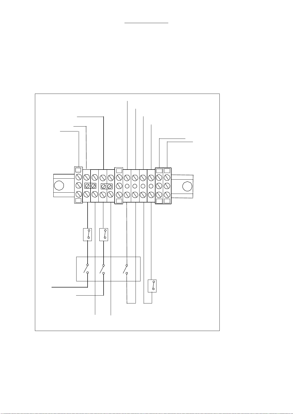
2.8 Electrical supply
The line cord of the Narkomat
+
is connected to an internal terminal block. Directly connected to this
terminal are convenience receptacles and the unit itself. Line supply to the receptacles is available
with the line cord connected. Line supply for the unit is switched by the main switch at the right side of
the unit. The two pole switched power supply is protected by each one 5A circuit breaker. The
switched line supply is connected to the AC IN connector on power supply board AVM 2-1. Another
third pole of the main switch is connected via the terminal to the board AVM 2-1 (X5:5,6), enabling to
detect a main switch OFF position or missing line supply.
1
1
1
1
1
8
Circuit breakers
Main switch
Convenience
receptacles
L 120/230 V
N 120/230 V
power supply board
Line cord
PE
3
4
3
4
2
2
2
2
7
2
Circuit breaker
battery
X5 pin 6
X5 pin 4
X5 pin 5
X5 pin 3
3
4
5
6
5
6
int. ground
wiring
ventilator
Power
supply board
5 A
5 A
The 120 V configuration has
additional circuit breakers
Fig. 1 Line Terminal Block, 120/230VAC Supply
Theory of Operation
16
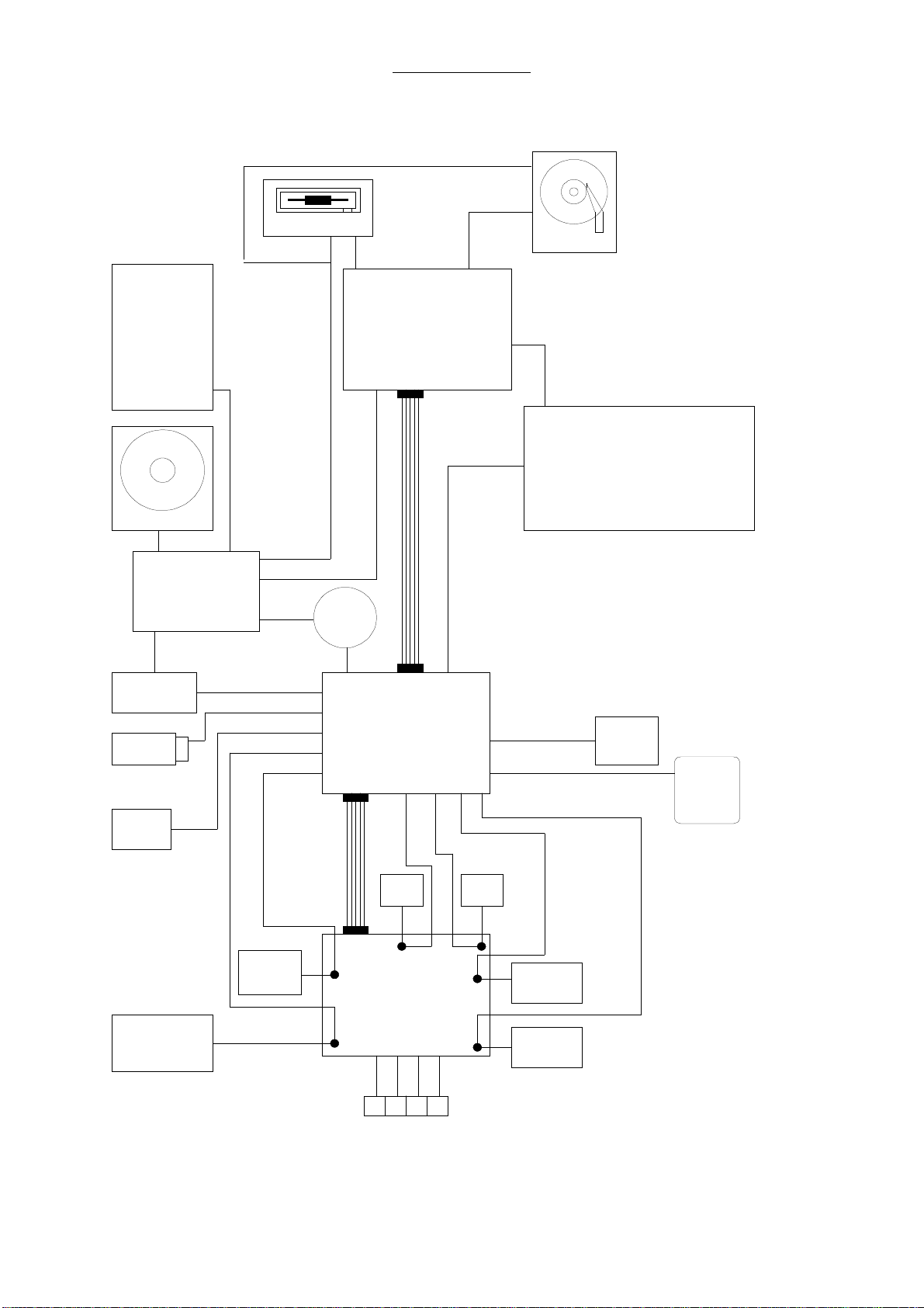
2.8.1 Electrical components
power supply
battery
main
switch
hard disc
heat
blanket
int. flow
sensor
ext. flow
sensor
P1P2
oxygen
sensor
solenoid valve
block
proportional
valve
transformer
floppy drive
RS 232
interface
I²C
interface
PT 100
motor
fan
flow meter
backlight
control panel
module 1
PC
module 2
AVM 3-1
module 2
AVM 3-2
ventilator
Fig. 2 Overview electrical components

Theory of Operation
17
2.9 Power supply module
The power supply module is located in the frame behind the drawers. This module serves for the
voltage supply of the ventilator modules 1 and 2, the flow meter block illumination, the patient circuit
heating blanket and the charging / discharging control for the battery. The power supply board allows
the supply with 230 VAC or 115 VAC, the supply voltage can be selected with a switch on the power
supply board.
Fig. 3 Power supply module
Theory of Operation
18
2.9.1 Connectors on power supply board AVM 2-1
Connector connected to Pin. def. Func. / Signal Color / No.
X1 Module 1 X1-1 +5V yellow
X1-2 GND red
X1-3 GND green
X1-4 +12V blue
Connector connected to Pin. def. Func. / Signal Color / No.
X2 X2-1 +5V
X2-2 GND
X2-3 GND
X2-4 +12V
Connector connected to Pin. def. Func. / Signal Color / No.
X3 X2-1 -
X2-2 -
X2-3 GND
X2-4 +12V
Connector connected to Pin. def. Func. / Signal Color / No.
X4 X4-1 +5V
X4-2 GND
X4-3 GND
X4-4 +12V
Connector connected to Pin. def. Func. / Signal Color / No.
X5 Battery, X5-1 BATT+ brown
Fuse for Battery X5-2 BATT- black
Main switch X5-3 Cir.break. bat. black 6
X5-4 Cir.break. bat. black 5
X5-5 Main switch black 4
X5-6 Main switch. black 3
Connector connected to Pin. def. Func. / Signal Color wire isolat.
X6 Transformer X6-1 sec.IIa 15VAC blue
RT110/12 secondary X6-2 sec IIa green
X6-3 sec. IIb 15VAC blue
X6-4 sec IIb green
Connector connected to Pin. def. Func. / Signal Color wire isolat.
X7 Transformer X7-1 prim.I, L120/230VAC
black/
RT110/12 primary X7-2 prim.I, N120/230VAC
orange
X7-3 prim.II,L120/230VAC
white
X7-4 prim. II, . violet
Connector connected to Pin. def. Func. / Signal Col. wire isolat.
X11 Transformer X11-1 Sec.Ia 22VAC red
RT110/22 secondary X11-2 Sec Ia yellow
X11-3 Sec. Ib 22VAC red
X11-4 Sec Ib yellow

Theory of Operation
19
Connector connected to Pin. def. Func. / Signal Color / No.
X12 int. connection X12-1 AC, N 110V/230V blue
AC IN terminal X12-2 AC , L 110V/230V black
Connector connected to Pin. def. Func. / Signal Color / No.
X13 Module 2 X13-1 +12V red
Board X13-2 GND blue
AVM 3-2 X13-3 +5V(1) red
X13-4 GND blue
Connector connected to Pin. def. Func. / Signal Color / No.
X14 Module 2 X14-1 +5V(2) red
Board X14-2 GND blue
AVM 3-2 X14-3 -12V red
X14-4 GND blue
Connector connected to Pin. def. Func. / Signal Color / No.
X15 Module 2 X15-1 Control Sign. white
Board X15-2 Control Sign. white
AVM 3-2 X15-3 Control Sign. white
X15-4 Control Sign. white
Connector connected to Pin. def. Func. / Signal Color / No.
X16 Module 2 X16-1 GND blue
AVM 3-2 X16-2 +31V red
Connector connected to Pin. def. Func. / Signal Color / No.
X17 solid state relay X17-1 22VAC to heat. bl. black
heating blanket X17-2 22VAC to relay black
X17-3 + Control voltage black
X17-4 GND black
Connector connected to Pin. def. Func. / Signal Color / No.
X22 DC-AC convert. X22-1 +supply voltage red
for flow meter X22-2 -
illumination X22-3 -
X22-4 GND black
2.9.2 Fuses on power supply board AVM 2-1
Fuse No. Fuse value Fuse protects
F1 4 A MT, medium slow-blow DC / DC-converter +5V
F7 8 A M, medium -blow DC / DC-converter +12V
F8 8 A M, medium -blow Transformer, Sec. IIa
F9 8 A M, medium -blow Transformer, Sec. IIb
F10 10 A T, slow-blow Transformer, Sec. Ia
F11 10 A T, slow-blow Transformer, Sec. Ib

Theory of Operation
20
2.9.3 Charging / discharging control for the battery:
The charging / discharging control for the battery is also located on the power supply board AVM 2-1.
Status indicators as red, green and yellow LEDs are located on the board to show functions like check
or charging of the battery.
2.9.4 Status Indicators Of Battery Control:
LED LED light Battery status
LED yellow (V28) Continuous charging
LED yellow (V28) Flashing check
LED green (V37) Continuous fully charged
LED red (V38) flashing or continuous. defect
Other manuals for Narkomat +
1
Table of contents
Other Heyer Medical Equipment manuals


Popular Medical Equipment manuals by other brands


Symmetry Surgical
Symmetry Surgical Bookwalter Instructions for use

Boston Scientific
Boston Scientific AMS 800 Instructions for use

DeVilbiss Healthcare
DeVilbiss Healthcare Vacu-Aide 7314 Series Instruction guide

Air Liquide
Air Liquide Presence PR Instructions for use

NSK
NSK SGS Series Operation manual

Spirosure
Spirosure FenomPro Instructions for use


