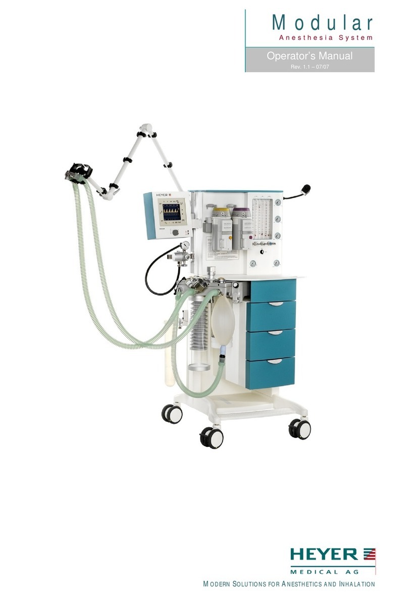
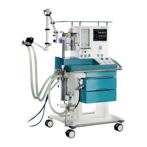
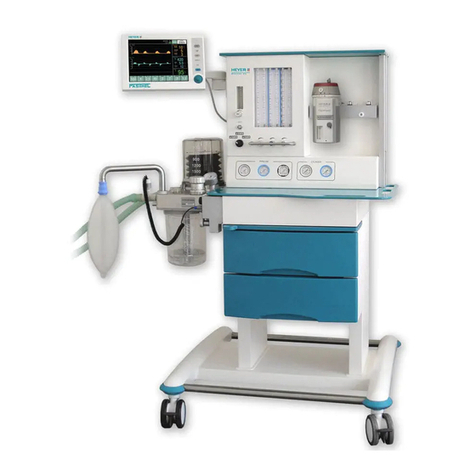
Heyer Modular+ User manual

HEYER Modular+
Anesthesia System
Service Manual
Rev.2.1.0
Software version Service software: 1.8

Table of Contents
2
HEYER MEDICAL AG
Carl-Heyer-Strasse 1-3
56130 Bad Ems
Germany
Tel. +49 - 2603 – 791 - 3
Fax. +49 - 2603 – 791 - 209
E-mail: info@heyermedical.de

Theory of Operation
0 Table of Contents
0
Table of Contents............................................................................................................................. 3
0.1
Table of Figures........................................................................................................................ 6
1
General Information.......................................................................................................................... 7
1.1
Guidelines ................................................................................................................................. 7
1.2
Product improvements.............................................................................................................. 7
1.3
Manufacturer’s Liability ............................................................................................................. 7
1.4
Manufacturer’s specification ..................................................................................................... 8
1.5
Updating status ......................................................................................................................... 8
1.6
Warning, Precautions and Notes .............................................................................................. 9
1.6.1
Warnings............................................................................................................................ 9
1.6.2
Precautions...................................................................................................................... 10
1.6.3
Notes................................................................................................................................ 11
2
Theory of Operation ....................................................................................................................... 13
2.1
Microprocessor-Controlled Ventilator...................................................................................... 13
2.2
Patient Module........................................................................................................................ 13
2.3
Gas Conditioning Unit............................................................................................................. 13
2.4
The Ventilator Unit .................................................................................................................. 13
2.5
Adjustable Alarms................................................................................................................... 13
2.5.1
P
max
limiting on alarm violation......................................................................................... 14
2.6
Fresh Gas Decoupling ............................................................................................................ 14
2.7
Compliance compensation...................................................................................................... 14
2.8
Electrical supply...................................................................................................................... 15
2.8.1
Electrical components...................................................................................................... 16
2.9
Power supply module.............................................................................................................. 17
2.9.1
Connectors on power supply board AVM 2-1.................................................................. 18
2.9.2
Fuses on power supply board AVM 2-1........................................................................... 19
2.9.3
Charging / discharging control for the battery:................................................................. 20
2.9.4
Status Indicators Of Battery Control:...............................................................................20
2.10
Module 1.............................................................................................................................. 21
2.10.1
Connectors on module 1..............................................................................................22
2.11
Ventilator Module 2, AVM 3-1 and AVM 3-2 ....................................................................... 23
2.11.1
Parts list module 2........................................................................................................ 24
2.11.2
Connectors on module 2..............................................................................................24
2.11.2.1
Plug connectors on board AVM 3-1 ........................................................................24
2.11.2.2
Plug connectors on board AVM3-2 ......................................................................... 25
2.12
Display................................................................................................................................. 25
2.13
Battery ................................................................................................................................. 25
2.14
Ventilator pneumatic............................................................................................................ 26
2.14.1
Ventilator pneumatic drive............................................................................................ 27
2.14.2
HP pressure reducer.................................................................................................... 27
2.14.3
LP- double stage pressure reducer.............................................................................. 27
2.14.4
Solenoid valves MV1 to MV4....................................................................................... 27
2.14.5
Pneumatic driving module............................................................................................ 28
2.14.6
Flow metering module.................................................................................................. 28
2.14.7
Tube color coding......................................................................................................... 28
2.15
The patient module (circle system) ..................................................................................... 29
2.15.1
Front and back side view on the patient module.......................................................... 29
2.15.2
Bottom and back side view on the patient module....................................................... 30
2.15.3
Functional representations of the patient module........................................................ 31
2.15.3.1
CMV mode, inspiration............................................................................................ 32
2.15.3.2
CMV mode, expiration............................................................................................. 33
2.15.3.3
Manual mode, inspiration ........................................................................................ 34
2.15.3.4
Manual mode, expiration......................................................................................... 35
2.15.3.5
Spontaneous mode, inspiration............................................................................... 36
2.15.3.6
Spontaneous mode, expiration................................................................................ 37
2.15.4
Components of the patient module..............................................................................38
2.15.4.1
Ventilation bellows system ...................................................................................... 38
2.15.4.2
Manual Respiration Bag / Reservoir........................................................................ 38
2.15.4.3
CO
2
absorber........................................................................................................... 38

Theory of Operation
4
2.15.4.4
Inspiratory and expiratory valves............................................................................. 38
2.15.4.5
Airway pressure relief valve .................................................................................... 38
2.15.4.6
Room Air valve........................................................................................................ 38
2.15.4.7
Diaphragm valves.................................................................................................... 38
2.15.2.7.1
Status of the diaphragm valves:....................................................................... 39
2.15.2.7.2
Machine OFF Or Ventilator In Standby............................................................ 39
2.15.2.7.3
Manual / Spontaneous Mode, INSPIRATION And EXPIRATION.................... 39
2.15.2.7.4
CMV Child / Adult Mode, INSPIRATION.......................................................... 39
2.15.2.7.5
CMV Child / Adult, EXPIRATION..................................................................... 39
2.15.2.7.6
CMV Adult, EXPIRATION And PEEP .............................................................. 39
2.15.2.7.7
Compliance Test Patient Module ..................................................................... 40
2.15.2.7.8
Leak Test Patient Module and Fresh Gas Module........................................... 40
3
Repair Information.......................................................................................................................... 41
3.1
Introduction ............................................................................................................................. 41
3.2
Warnings and precautions ...................................................................................................... 41
3.2.1
Precautions...................................................................................................................... 41
3.2.2
Warnings.......................................................................................................................... 41
3.3
Troubleshooting Guidelines .................................................................................................... 42
3.4
Troubleshooting Charts........................................................................................................... 42
3.4.1
Error Messages during ventilation................................................................................... 42
3.4.2
Alarm messages during the compliance test, leak test and O2 calibration.....................46
3.4.2.1
Messages during the system tests........................................................................... 47
3.4.3
Symptoms of Fuse Failures............................................................................................. 49
3.5
Required Tools........................................................................................................................ 50
3.6
Disassembly instructions......................................................................................................... 50
3.6.1
Connecting and disconnecting vaporizers....................................................................... 50
3.6.2
Removing the compressed gas tanks (PIN-Index).......................................................... 50
3.6.3
Removing the Patient Module..........................................................................................51
3.6.4
Removing the CO
2
Absorber Canister............................................................................. 51
3.6.5
Removing the Bellows and Dome System ......................................................................51
3.6.6
Removing the Airway Pressure Limiting Valve (APL)...................................................... 51
3.6.7
Inspecting/replacing the Decoupling, Bellow and Expiratory Valves............................... 52
3.6.8
Disassembling the Room Air, Inspiration and expiration valves...................................... 52
3.6.9
Removing the Gas Block Module .................................................................................... 52
3.6.10
Removing the flow tubes.............................................................................................. 52
3.6.11
Removing the pressure gauges ................................................................................... 53
3.6.12
Removing the Module 2 Circuit Board Set................................................................... 53
3.6.13
Removing Module1 Circuit Board Set.......................................................................... 53
3.6.14
Removing the Power Supply Module........................................................................... 53
3.6.15
Removing Internal Regulators, Proportional Valve and Flow Divider.......................... 54
4
Maintenance and Calibration ......................................................................................................... 55
4.1
Introduction ............................................................................................................................. 55
4.2
Calibration Warnings and Precautions.................................................................................... 55
4.3
Test Procedure........................................................................................................................ 56
4.3.1
General ............................................................................................................................ 56
4.3.2
Inspecting/replacing consumable parts ........................................................................... 56
4.3.3
Power supply checks....................................................................................................... 61
4.3.4
Functional Tests............................................................................................................... 62
4.3.4.1
Pneumatic tests........................................................................................................ 62
4.3.4.2
Alarm Tests............................................................................................................... 63
4.3.4.3
Electrical Tests ......................................................................................................... 65
4.4
Service Software..................................................................................................................... 66
4.5
Key code Access..................................................................................................................... 67
4.6
Navigation ............................................................................................................................... 68
4.6.1
System Testing................................................................................................................ 70
4.6.2
Coefficient programming.................................................................................................. 79
4.6.2.1
O
2
sensor calibration ................................................................................................ 79
4.6.2.2
P1 Pressure sensor calibration................................................................................. 81
4.6.2.3
P2 Pressure sensor calibration................................................................................. 83
4.6.2.4
Temperature Sensor Calibration .............................................................................. 85
4.6.2.5
Proportional Valve Calibration.................................................................................. 87
4.6.2.6
Internal Flow Sensor Calibration .............................................................................. 92

Theory of Operation
5
4.6.2.7
Characteristic of the Proportional Valve................................................................... 94
4.6.2.8
External Flow Sensor Calibration............................................................................. 96
5
Preventive Maintenance................................................................................................................. 99
5.1
6 Month Service Interval .........................................................................................................99
5.2
12 Month Service Interval .....................................................................................................100
5.3
36 Month Service Interval .....................................................................................................100
5.4
Cleaning................................................................................................................................ 101
5.4.1
Cleaning and disinfecting the apparatus ....................................................................... 101
5.4.2
Cleaning and sterilizing the Patient Module .................................................................. 101
5.5
Battery Replacement and Maintenance................................................................................ 101
5.5.1
Battery replacement....................................................................................................... 101
5.5.2
Battery Maintenance...................................................................................................... 101
6
Order Information ......................................................................................................................... 103
Table of contents
Other Heyer Medical Equipment manuals
Popular Medical Equipment manuals by other brands

Getinge
Getinge Arjohuntleigh Nimbus 3 Professional Instructions for use

Mettler Electronics
Mettler Electronics Sonicator 730 Maintenance manual

Pressalit Care
Pressalit Care R1100 Mounting instruction

Denas MS
Denas MS DENAS-T operating manual

bort medical
bort medical ActiveColor quick guide

AccuVein
AccuVein AV400 user manual

