HeyGears Reflex User manual
Quickstart V1.0
Personal Desktop 3D Printer
Follow us @HeyGears
USA-17931 Sky Park Circle, Suite E, Irvine, CA, 92614
CHN-Block B2, 501, 601, Enterprise Accelerator, Kaifa District, Guangzhou City
Tel: +1 (318) 353-4295 (Global)/ +1 (949) 418-9418 (USA) / +44 148-396-8549 (EU)
heygears.com [email protected]

Components
2
Items & Parameters
1
Thank you for choosing HeyGears. For safety, please contact HeyGears support staff for
assistance regarding unpacking and installing the machine. If you fail to comply with the
instructions in this manual, HeyGears will not be liable for the consequential damages unless
required by federal and local ordinances.
Please keep this operation manual properly for future reference. The pictures are for reference
only and the products are subject to the actual product.
This quick start must be read and
understood before operating the machine
Printer
X1
Power Cord
X1
Resin Tank Lid
X1
Build Platform
X1
Release Film
Spare Module
X1
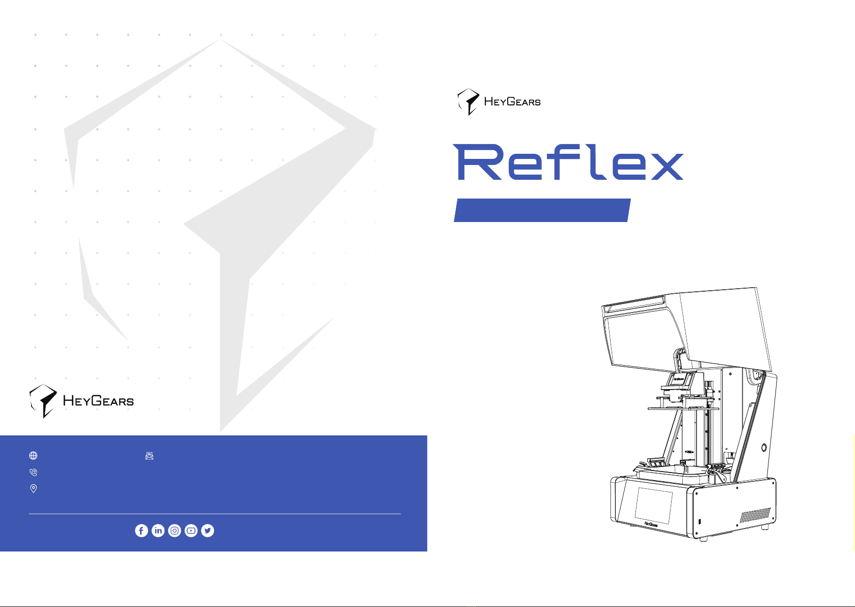
Build Platform
Resin Tank
Detachable Resin
Filling Gate
Touch Screen
Suspension Button
Power Switch
Power Port
Resin Bottle
Insert Location
Air Tube Port
UltraCraft Reflex
400*420*572 mm
UltraCraft Rapid
Production System 100-240 V~ 50/60 Hz
25 kg
350 W
Snipper
X1
Allen Wrench
X3
Rubber Gloves
X2
Parts Removal
Tool
X1
Scraper
X10
Filter Paper
Main Axis
Temperature and
Liquid Level Sensor
Hood
USB Port
Resin Tank
X1
Simple Cleaning Box
X1
Screwdriver
X1 X5
Inflation Module Port
Ethernet Port
Name
Model
Size
Input
Weight
Power
Installation Requirements
3
Operation Steps
4
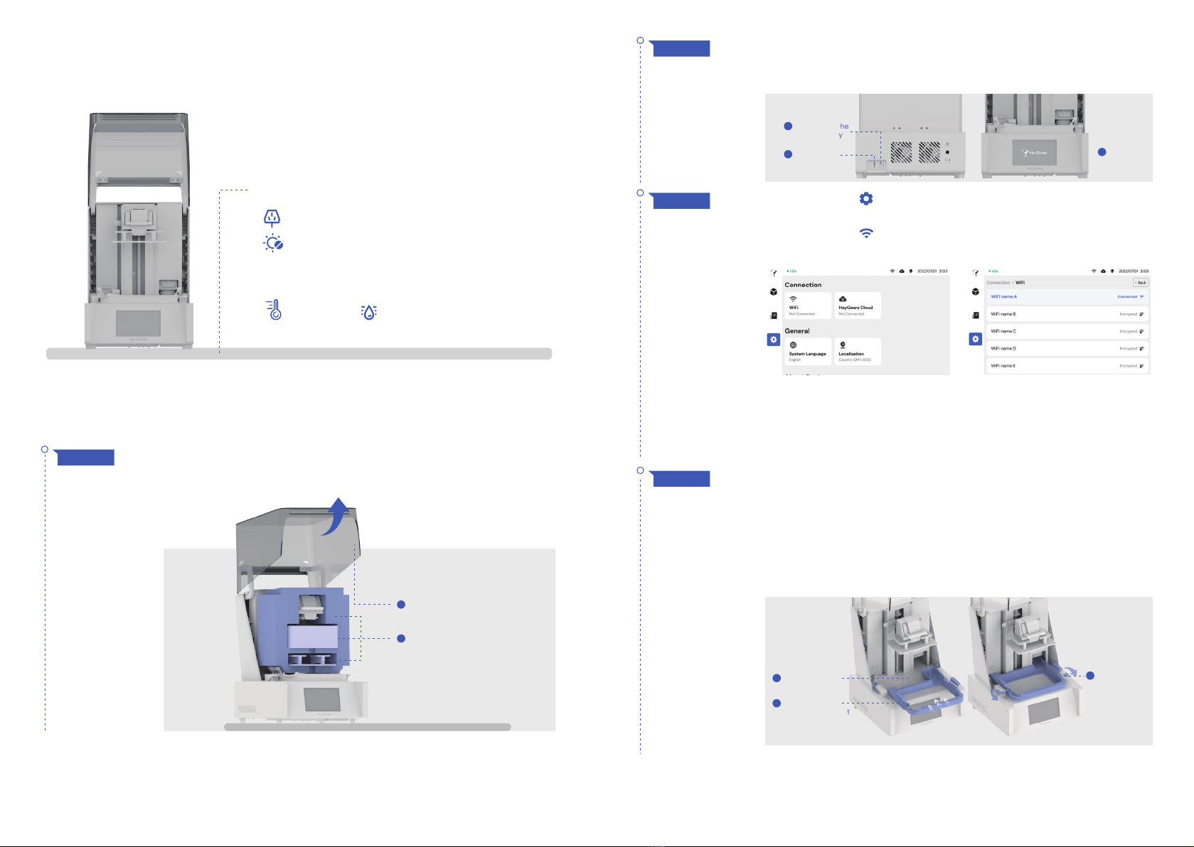
Connect the power supply as shown, and turn on the power switch,
then the touch screen lights up to indicate that the power is
successfully connected.
STEP 2
Place the printer on a smooth horizontal surface, check the
appearance of the printer to make sure it is in good condition, lift
the hood to the highest position and remove the filler inside.
STEP 1
Position the printer onto a stable table
100-240 V power socket nearby
Protected from exposure to direct sunlight
18~25°C
Temperature & Humidity Control:
<50%
Connect to the
power supply
1
Turn on the
switch
2Screen
lights up
3
Click the button on the left navigation bar to enter the "Settings"
interface.
Click the button in the function list to enter the "Connection"
interface.
Go through the list of available Wi-Fi, click on which you want to
connect to: if the Wi-Fi you choose does not require password
verification, click Confirm and the printer will automatically connect to
it. Otherwise, you need to type in the password at first connection time.
STEP 3
Remove the resin tank inside the printer, and check whether the
outer foam and release film are complete or not. Tear off the
dustproof film of the LCD screen and ensure that there is no dust
and foreign matters on its surface.
After checking, hold its handles on both sides, aligning with the
locking module on both sides, install it into the cabinet with the
overhang part facing inward, then pull the locking handles forward.
You can shake the resin tank slightly to ensure that it is locked.
STEP 4
Tear off the
dustproof film
1
Install the resin
tank in the correct
direction
2
1
2
Tighten the
locking handle
by pulling
forward
3
Take out the filler
buid platform and cleaning box
Open the hood

Replace the release film
5
Follow the Ultraflow guide to complete the device binding and
pre-processing, and send the job to the printer for printing.
In the idle status, gently pull the resin bottle up along the track
and press the suspension button on the side of the printer, then
release the bottle so that it is stuck in suspension. When the resin
no longer drips naturally from the bottle, remove the bottle along
the rail and press the suspension button again to return it to the
original state.
When printing finished, open the hood and unlock the build
platform to take it out.
If you need to recover residual resin from the parts, hang the build
platform on the main axis at an angle as shown until the resin no
longer drips heavily.
After removing the platform, follow the instructions for the
post-processing like washing, removing parts and supports, and
post-curing etc.
STEP 7
STEP 6
STEP 5
STEP 8
STEP 1
Take out the liquid & temperature sensor and install it in the resin
tank as shown below. Make sure that the sensor is magnetically
attracted to the resin tank, and the convex part at the end is
inserted into the specified position, then you can shake it gently to
make sure it is fitted well.
Take out the build platform in the package and keep the locking
wrench raised, then install the build platform along the slide. Inset
it to the bottom, lock down wrench and close the hood.
Fully shaken the bottle and open it, then unscrew the cap as shown.
Insert the resin bottle downward along the slot into the printer, and
lift the top cover of the printer if using a 2L resin bottle.
Insert the resin bottle until you get tactile feedback and the display
shows that the resin bottle is inserted.
Keep the locking wrench raised
1
Twist the cap
counterclockwise
1
Install the build platform along the slide
2
Lock down the wrench
3Close the hood
4
CAUTION: Once the resin bottle is inserted into the printer,
the resin will flow into the resin tank, please make sure the
resin inserted is correct.
Resin tank and Release Film Spare Module are shown in the picture:
Replacement steps
Release Film Spare Module
Insert the resin bottle
downward along the slot
into the printer
2
1 2
Keep the platform unlocked, install the
platform diagonally as shown in the picture to
the end and wait for the resin inside the
model to flow out naturally
Lifting the locking handle and remove the
build platform with parts slightly
Resin Tank

Cautions
6
Remove the resin filling gate in the direction shown.
STEP 2
STEP 3
STEP 4 Use the attached wrench to remove the screws of the release film
at the bottom of the resin tank. Take out the release film after all
the screws are removed.
Remove the resin tank by pulling back the locking handle on both
sides of it.
STEP 5 Install the new release film into the resin tank in the same position
and re-lock the removed screws to the original holes. Reinstall the
resin tank according to the guidelines.
Please close the hood in time after installing or removing
the platform and resin tank to avoid dust entering the
printing area.
Remove the screws
1
Pull back the locking handle
1Lift up the resin tank slightly to remove it
2
Take out the release film
2
Install the new release film
1
Re-lock the screws
2
Apply the film life detection
label to the resin tank
3
Remove the resin filling gate
Pull out the
resin bottle upward
1 2 43
01
Before removing the resin tank or resin bottle, please
press down the suspension button to stuck the resin bottle
and wait for several minutes until the resin stops drippong.
02
It is recommended to store the resin tank and release film
spare module in a dust-proof place and keep the
temperature between 20~25℃.
03
Please avoid contaminating the liquid level sensor power
supply with resin.
04
Please clean the liquid level and temperature sensor
probes when changing the material; Not to invert the
sensor when the probes are covered with resin.
05
Press the suspension button
Release the resin bottle so
that it is stuck
Remove the resin bottle
when the resin no longer
drips from the bottle
Press the suspension
button again to return it to
the original state
Table of contents


