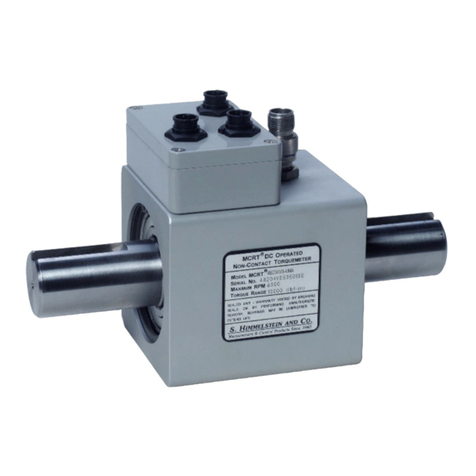
Himmelstein MCRT 48600V Operating instructions

1
© 2022 S. Himmelstein and Company—all rights reserved. www.himmelstein.com
NEXTGEN ULTRA PRECISION DIGITAL TORQUEMETERS
INSTALLATION, OPERATION,AND TROUBLESHOOTING GUIDE
NEXTGEN ULTRA PRECISION DIGITAL TORQUEMETERS
INSTALLATION, OPERATION,AND TROUBLESHOOTING GUIDE
& COMPANY
2490 Pembroke Avenue, Hoffman Estates, IL 60169 • 847-843-3300
www.himmelstein.com
Revision F • April 2022
APPLIES TO SERIES
MCRT®48600V
MCRT®48800V
MCRT®49800V
MCRT®48850V/48851V
MCRT®59800V
MCRT®79800V
NGT

NextGen Ultra Precision
Digital Torquemeters
Installation, Operation, and Troubleshooting Guide
Customer:
Model Number:
Serial Number:
Factory Reference Number:
Horsepower at Max Rated Torque and Speed:
Maximum Rated Torque (lbf-in):
Low Range (if present) Torque Rating (lbf-in):
Torque Overload Capacity (lbf-in):
Overrange Rating: 150% on all outputs.
Maximum Speed (rpm):
Performance Code:
Foot Mount: ❑Yes ❑No
Speed/Horsepower: ❑Yes ❑No
Special Features:
Scaling, Units of Measure and Pin Assignments if Different Than Default
Torque Range(s):
Speed Range:
Power Range:
Filter Cutoff Requency (Hertz):
Password Protection [FIS = Off]: ❑On ❑Off
The attached Calibration Certicate lists actual calibration data. The calibration was done in Himmelstein’s NVLAP Accredited
Laboratory (NVLAP Lab Code 200487-0). For details, visit www.himmelstein.com or the ‘laboratory accreditation’ link @
www.nist.gov. Cal values are loaded on power up. Calibration data can be accessed using a PC and the supplied software.
& COMPANY
2490 Pembroke Avenue, Hoffman Estates, IL 60169 • 847-843-3300
www.himmelstein.com

3
© 2022 S. Himmelstein and Company—all rights reserved. www.himmelstein.com
Contents
I. Introduction ....................... 4
A. Mechanical Installation ............. 4
A.1 Applicability................................. 4
A.2 References .................................. 4
A.3 Coupling Selection ........................... 4
A.4 Coupling Installation.......................... 5
A.5 End-to-End Orientation........................ 5
A.5.1 Effect on Signal Polarity ..................... 5
A.5.2 Effect onTorquemeterThrust Capacity.......... 5
A.6 Vertical Installations & Belt/Chain Drives ......... 5
B. Electrical Installation ............... 6
B.1 Applicability ................................. 6
B.2 Stator Connectors ............................ 6
B.3 Wiring Cautions andTips ...................... 6
B.4 As Delivered Pin Connections .................. 6
B.5 Analog Output Default Pin Assignments Summarized... 7
B.5.1 Eight (8) Pin Connector: MCRT®48600V, 48800V,
48850V/48851V, 49800V, 59800V with
Speed/Power Option........................... 7
B.5.2 Eight (8) Pin Connector: MCRT®48600V, 48800V,
48850V/48851V, 49800V, 59800V without
Speed/Power Option........................... 7
B.5.3 Eight (8) Pin Connector: MCRT®79800V with
Speed/Power Option........................... 7
B.5.4 MCRT®79800V without Speed Option -
Default Pin Assignments ....................... 7
B.6 Cables...................................... 8
B.7 Calibration Function .......................... 8
B.8 Clockwise (CW) and Counterclockwise (CCW)
Denition .................................... 8
B.9Tare Function ................................ 9
B.10 Torque Zeroing .............................. 9
C. Operating & Safety Considerations .... 9
C.1 Applicability ................................. 9
C.2 AllowableTorque Loads ....................... 9
C.2.1 Overload Considerations..................... 9
C.2.2 Fatigue Considerations ...................... 9
C.2.3 Starting High Inertias with Electric Motors ...... 9
C.3 Allowable Bearing Loads ..................... 10
C.4 Allowable Extraneous Loads .................. 10
C.4.1 Allowable Bending Loads ................... 10
C.4.2 AllowableThrust Loads ......................11
C.5 Operating Speeds ............................11
C.6 High Speed Operation ........................11
C.7 Lubrication..................................11
C.7.1 Standard MCRT®Torquemeters ................11
C.8 Contaminants ...............................11
C.9 Hazardous Environments ......................11
D. PC Interface Software ............. 12
D.1 PC Interface Software Description .............. 12
D.2 Change Sensor Setup ........................ 12
D.3 Display Measured and Computed Data ......... 12
D.4Test Control ................................ 12
D.5 Perform Dead Weight Calibration .............. 12
D.6 Calibration Intervals ......................... 12
E. Troubleshooting................... 13
E.1 Scope ..................................... 13
E.2 Preliminary Inspection ....................... 13
E.2.1Transducer ................................ 13
E.2.2 Cabling and Earth Grounding ................ 13
E.2.3 Readout Instrument/Data Acquisition System/
Controller................................... 13
E.3Torque Subsystem ........................... 13
E.3.1 No Output WhenTorque is Present ............ 13
E.3.2 Constant Output Regardless of ShaftTorque .... 13
E.3.3 Apparent Zero Drift......................... 13
E.3.4 Signal Instability........................... 13
E.3.5 System Will Not Zero ....................... 13
E.4 Speed Subsystem ........................... 14
E.4.1 No Signal Output When Shaft is Rotating ...... 14
E.4.2 Erratic Output ............................. 14
E.4.3 Speed Pickup Replacement .................. 14
E.5 Power Subsystem ........................... 14
Appendix I: Detailed Specications ..... 14
Appendix II: Installed Units of Measure .. 14
Appendix III: Mating Stator Connector Part
Numbers .......................... 15
Appendix IV: Available Interconnect
Cables ............................ 15
Appendix V: Driving External Optical
Relays with Status Flags ............. 15
Appendix VI: Available Computer Port
Adapters .......................... 16
Appendix VII: Torquemeter to RS232
Computer Port Cabling ............... 16
Appendix VIII: Torquemeter to RS422
Computer Port Cabling ............... 16
Appendix IX: Foot Mounted Versus
Floating Shaft Installations ............ 17
Appendix X: Vertical Installations....... 17
Appendix XI: Fatigue Considerations .... 18
Appendix XII: High Speed Operation .... 18
Appendix XIII: Hazardous Environments . 19
Appendix XIV: Belt and Chain Drive
Considerations ..................... 19
Appendix XV: Serial Communications
for the Next Generation Torquemeter ... 20
Communication Port Settings..................... 20
General Conventions Used inThis Document........ 20
General information ............................ 20

4© 2022 S. Himmelstein and Company—all rights reserved. www.himmelstein.com
These transducers measure and output shaft torque,
power and speed. Speed and power are optional. They
have no pots, switches or manual adjustments. Null,
scaling and units of measure are stored in non-volatile
memory. Digital computation of power is errorless.Thirty
three (33) common units of measure are supported. You
can select any supported unit of measure(s) without the
need to re-calibrate. Thirteen (13) selectable Bessel lters
avoid delay distortion and overshoot and assure optimal
measurement response in your application(s). Input
power is a single, unregulated dc supply. Reverse polarity
protection is standard.
If you re-calibrate, previous calibration values are archived.
Pin strapping and serial commands enable simultaneous,
traceable* torque/power/speed calibrations, remote tare,
tare clear, max/min reset and remote zeroing. Password
protection may be invoked if needed. Included interface
software operates on Windows-based PCs and displays
and plots real time data. Use it to select ±5V or ±10V
analog outputs, lter cutoff frequency, scaling, units of
measure, zero, tare, clear tare, store data, etc. and/or to
control measurements.
Strain gages sense torque on the rotor where it is digi-
tized and transmitted to stator circuitry. That circuitry
decodes and conditions the signals as scaled analog and
digital outputs. Both signal and power transfer is done
inductively, without brushes or any physical contact. The
transmission system doesn’t generate noise or wear and
is immune to ambient noise, vibration, lubricants and
other hostile environments.
Circuitry is shielded from RFI and external magnetic
elds which fact, combined with the absence of low
level cables, yields extraordinary noise immunity, even
close to large electric machines. Elimination of slip rings,
brushes, fragile ferrites, and other limited-life, noise-gen-
erating and noise susceptible elements further increases
performance and reliability. Moreover, the non-ferrite
design makes these transducers suitable for diesel and
other hostile applications.
* NIST traceable calibration performed in our accredited Cal Lab (NVLAP LAB
Code 200487-0). For details visit www.himmelstein.com or www.nist.gov.
I. Introduction
A. Mechanical Installation
A.1 Applicability
This discussion is applicable to all models.
A.2 References
MCRT®48800V, 49800V, 59800V, and 79800V transducers
are mechanically interchangeable with the MCRT®48000V,
49000V, 59000V and 79000V, DC Operated Torquemeter
models with the same full scale ranges and overload
ratings.That is, they share the same physical dimensions.
However, unlike the analog torquemeters, they:
• Use advanced digital technology to measure torque
and transfer it to the stator
• Have integral digital speed (an option) conditioning
and output circuitry
• Calculate shaft power (an option)
• Have no manual adjustments
• Output three 5V or 10V analog signals (user select-
able)
• Have thirteen selectable lter cutoff frequencies
• Have a full duplex RS232/422/485 port
• Come with PC interface software
• Have improved long term drift
• Support 33 mouse selectable units of measure.
These Torquemeters also have improved temperature
performance, overrange ratings, combined nonlinearity
and hysteresis, long term stability, wider bandwidth and,
when present, much faster power computations than
earlier models.
A.3 Coupling Selection
Your torquemeter installation method dictates the type of
coupling needed.There are two installation methods, i.e.,
a oating shaft and a foot mount.
Floating shaft installations are applicable to both shaft
and anged type torquemeters. A single ex coupling is
installed at each shaft end. It takes out angular misalign-
Single-Flex
Couplings
Flexible
Restraining
Strap
Torquemeter Installed
as Floating Shaft
Driver
Load
Figure 1. Floating Shaft Installation

5
© 2022 S. Himmelstein and Company—all rights reserved. www.himmelstein.com
Driver
Double-Flex
Couplings
Foot Mounted
Torquemeter
Load
Figure 2. Foot Mounted Installation
To Avoid Damage Or Injury
• Use xturing to support the hot shaft.
• Use insulated gloves when handling hot parts.
• Stop the hub installation if the pressing force exceeds
a few pounds. Remove the coupling. Cool all parts,
and then inspect for burrs on the coupling bore, shaft,
keys and keyways. If the parts are burr free, check the
bore size and verify the coupling keyway squareness.
• Don’t allow uids to enter the torquemeter.
A.5 End-to-End Orientation
A.5.1 Effect on Signal Polarity
MCRT®torquemeters are bi-directional. Their output
signal polarity reverses when the direction of transmitted
torque reverses. Himmelstein uses the following conven-
tion for dening torque direction.
CWTorque: the shaft turns CW, when viewed from
the driven end
CCWTorque: the shaft turns CCW, when viewed from
the driven end
Reversing a torquemeter end-for-end doesn’t change the
torque direction or magnitude. Therefore, it will have no
effect on the torquemeter output signal. When in doubt
about shaft torque direction, observe the output signals
during normal machine operation. A positive signal
output indicates CW torque per the above denition. A
negative output signal signies a CCW torque.
Torque signal polarity is xed at the factory and is not
eld changeable.
A.5.2 Effect on Torquemeter Thrust Capacity
Orienting a foot mounted torquemeter per Figure 3 will
provide increased uni-directional thrust capacity. Because
dynamic thrust loading is usually bi-directional, it’s safest
to limit bearing axial (thrust) loads per ¶ C.3. Orienta-
tion does not affect the thrust capacity of torquemeters
installed as oating shafts.
When axial bearing loads are uni-directional, the orien-
tation illustrated in Figure 3 increases the unidirectional
thrust rating by a factor of four (4). Remember, the
increased uni-directional rating applies only to optimum
orientation of foot mounted torquemeters.
A.6 Vertical Installations & Belt/Chain Drives
Vertical installations frequently require special mounting
and coupling selection considerations. See Appendix X for
vertical installations and Appendix XIV for belt/chain drives.
ment, and the torquemeter “tilts” to take out parallel
misalignment. Use a exible strap to prevent housing
rotation and to strain relieve the torquemeter electrical
cable. Caution: If electrical connections are run in a short,
rigid conduit, you must foot mount the torquemeter.
Alternately, use exible conduit and single ex couplings.
Install a foot mounted torquemeter between double ex
couplings as shown.The double ex couplings accommo-
date both parallel and angular misalignments.
Appendix IX discusses the choice of a foot mounted or
a oating shaft installation. It also contains additional
comments on coupling selection. For either installation
method, choose couplings that will handle the:
• Expected shaft end oat
• Parallel and angular misalignments
• Maximum expected shaft speed
• Maximum expected shaft torque
• Expected extraneous loading.
A.4 Coupling Installation
Use a slight interference t (0.0005 inches per inch of shaft
diameter) and follow the coupling manufacturers’ instruc-
tions. Before installation, lightly coat the torquemeter shaft
with an anti-seizing compound suitable for use at 400 deg.
F. Next, heat the coupling hub, not the torquemeter, to
approximately 400 deg. F. Then, install the coupling.
The heated coupling hub should “slip” on the torquemeter
shaft without signicant resistance.That is, coupling instal-
lation force shouldn’t exceed 10% of the axial load tabulated
in ¶ C.3. Next, allow the assembly to cool to room tempera-
ture.Then, repeat the process for the second coupling.
If desired, use forced air to accelerate cooling. Air cooling
avoids contaminating the torquemeter with anti-seizing
compound. If cooling is speeded with water dampened
rags, orient the torquemeter to prevent entry of water
mixed with anti-seizing compound. Otherwise, internal
damage can occur.
After coupling installation, verify that:
• Clearance exists between the coupling and the
torquemeter stator, and
• The shaft-to-coupling t is snug enough to prevent
vibration induced coupling motion.
Option Z Speed Pickup
Preferred Thrust Direction
➨
Figure 3. PreferredThrust Path

6© 2022 S. Himmelstein and Company—all rights reserved. www.himmelstein.com
B. Electrical Installation
B.1 Applicability
This section is applicable to all MCRT®48600V,
48800V, 48850/48851V, 49800V, 59800V and
79800V Ultra Precision DigitalTorquemeters.
B.2 Stator Connectors
Four connectors as follows: one 10 pin, one 8
pin, and twin (2) 6 pin connectors. If ordered
without readouts, one each 10, 8 and 6 pin
mating connector is supplied. A connector
terminated, RS422 twenty foot Com Port to PC
cable is also furnished.The following tables list
pinouts for the 4 user connectors.
Note: to invoke a command, ground the
control pin or drive it with a logic zero.
Output ags are Low (0V) when within
rating and High (3V) if outside rating;
see Appendix V if you wish to drive an
external optical relay.
B.3 Wiring Cautions and Tips
Reverse polarity protection is standard. Although any wire
may be used, shielded cable performs best in noisy envi-
ronments and is strongly recommended.The shield should
oat at theTransducer, tie the other end to earth ground.
• Caution: Don’t connect a Transducer to a Power
Supply that also drives inductors or solenoids.
Induced switching transients may cause damage or
noise.
• Connect the transducer stator directly to earth
ground – a building’s structural steel or a oor rod. If
neither is available, drive a six foot copper rod into
the oor. Then run separate ground straps between
it and the test stand components as shown in the
sketch. Don’t “daisy chain” the connections; see
Figures 4 and 5.
• If an IGBT-based variable frequency drive (VFD) is
used, follow its installation manual. Improperly
installed VFDs can cause premature motor and
cable failures, as well as reading errors from exces-
sive noise. VFDs should have shielded power and
motor cables. Belden Types 29500 thru 29507cable
are designed for VFD use. See “Cable Alternatives
for PWM AC Drive Applications” at www.belden.
com. Use the connections shown in Figure 20 of
that document. For best results in noisy environ-
ments, use a differential input amplier and the
differential output conguration.
B.4 As Delivered Pin Connections
Unless specied in the customers’ order, Torquemeters
are delivered with the default pin connections dened in
¶ B.2 and expanded in ¶ B.5. If specied differently, the
connections are dened on the manual front page or in
an equivalent document.
10 Pin Connector Pinout
Function Pin
Invoke Clockwise Calibration A
Tare Data B
Clear Tare C
Ground Return D
+ Power Input (10 to 26 VDC) E
Resets Max/Mins F
Temperature Status. See Appendix V if you wish to drive an optical relay. G
Torque Status. See Appendix V if you wish to drive an optical relay. H
Speed Status. See appendix V if you wish to drive an external optical relay. J
Invoke Counterclockwise Calibration. K
Twin 6 Pin Connector Pinouts
Function Pin
+ TXD A
Ground for RS422/485, Open for RS232 B
Ground C
- RXD or TXD D
+ RXD or RXD E
- TXD F
Both identical connectors are wired in parallel to facilitate RS485 connections to
multiple Torquemeters. Either connector may be used for RS232 or RS422 service.
The terms TXD and RXD apply to RS232 applications. The terms ±TXD and .±RXD
apply to RS422 and RS485 applications.
8 Pin Connector Pinout
Function Pin
Speed Analog Out (±10V) A
Power Analog Out (±10V) B
Analog Signal Ground C
+ Power Input (10 to 26VDC) D
Invoke Clockwise Calibration E
Invoke Counterclockwise Calibration F
Torque Analog Out (±10V) G
Digital Ground/Power Return H
Default pinout is shown; it assumes Option Z is present. Default without Option Z
is: Pins A and B are +5V and -5V Torque analogs thus, they provide a differential
±10V torque output. Pin G remains a ground referenced ±10V torque signal.

7
© 2022 S. Himmelstein and Company—all rights reserved. www.himmelstein.com
Load Device
Torquemeter
Drive Motor
Earth Ground
DAS/Controller
Machine Base
Note: Use separate ground straps
Load Device
Torquemeter
Drive Motor
Earth Ground
DAS/Controller
Machine Base
Load Device
Torquemeter
Drive Motor
DAS/Controller
Machine Base
Figure 4. Correct System Earth Grounding
Figure 5. Examples of Incorrect Earth Grounding
B.5 Analog Output Default
Pin Assignments Summarized
Unless requested differently, units are shipped with
the default pin assignments listed below. The user may
re-assign any three analog output signals present in any
combination. For example, using the supplied software,
if Torque, Speed and Power outputs are present (Code Z
Option), you can outputTwoTorque Signals and Power, etc.
B.5.1 Eight (8) Pin Connector: MCRT®
48600V, 48800V, 48850V/48851V, 49800V,
59800V with Speed/Power Option
Pin A +10V Speed Output
Pin B ±10V Power Output
Pin G ±10VTorque Output
Pin C Analog Ground
B.5.2 Eight (8) Pin Connector: MCRT®
48600V, 48800V, 48850V/48851V, 49800V,
59800V without Speed/Power Option
Pin A
±
5VTorque Output
Pin B ±5VTorque Output
Pin G ±10VTorque Output
Pin C Analog Ground
B.5.3 Eight (8) Pin Connector: MCRT®
79800V with Speed/Power Option
Pin A +10V Speed Output
Pin B ±10V Low RangeTorque Output
Pin G ±10V High RangeTorque Output
Pin C Analog Ground
B.5.4 MCRT®79800V without Speed Option -
Default Pin Assignments
Pin A ±10V Low RangeTorque Output
Pin B ±5V High RangeTorque Output
Pin G ±10V High RangeTorque Output
Pin C Analog Ground

8© 2022 S. Himmelstein and Company—all rights reserved. www.himmelstein.com
B.6 Cables
Shielded cables should be used to avoid noise pickup.The
shields should oat at theTorquemeter end and all should
be terminated at a single earth ground. Don’t run trans-
ducer cables in close proximity to power lines.
Figure 6 illustrates cable connections for multipleTorque-
meters with Option Z, conditioned Speed and Power
Outputs, to a host computer with an RS232 port. If the
computer has an RS422 port, a converter isn’t needed. For
computers with USB ports see Appendix VI.
B.7 Calibration Function
These Torquemeters have rotor side, bi-polar shunt cali-
bration. That is, a stable, precision resistor is shunted
across the torque bridge in response to a user initiated
command. The resultant Cal signal is referenced to the
factory dead weight torque calibration and, is NIST trace-
able. Thus, when invoked, it permits calibration of the
users’ data acquisition system, traceable to NIST. Further-
more, it permits verication of the entire data chain in
both the CW and CCW directions.
Calibration may be invoked from your PC using the
supplied interface software. Alternately you can invoke
calibration by grounding pins as follows:
CW Calibration: ground Pin A on the 10 pin connector,
or ground Pin E on the 8 pin connector.
CCW Calibration: ground Pin K on the 10 pin connector,
or ground Pin F on the 8 pin connector.
Invoking a Cal Check produces simultaneous calibration
signals for all outputs, i.e,Torque and, with Option Z present,
Speed and Power.The calibration signal will remain on until
the short is released. For that reason it should be invoked
while the driveline torque is at zero; if locked-in torque is
present, break one of the shaft couplings.
Always remove the Cal Check command before running
a test.
Equivalent calibration values are listed on the Calibration
Certicate which documents NIST traceability*. They can
also be accessed using the furnished software. Calibration
values are determined in S. Himmelstein and Company’s
accredited* (NVLAP Lab Code 200487-0) calibration labo-
ratory. The user may perform a dead weight calibration
and store the results in memory, using furnished soft-
ware.The original cal data is archived.
B.8 Clockwise (CW) and
Counterclockwise (CCW) Denition
CWTorque causes the shaft to turn CW when viewed from
the driven end. CCWTorque causes the opposite rotation.
Power polarity tracks the torque. Himmelstein uses the
following polarity denitions:
CWTorque produces a positive output signal.
CCWTorque produces a negative output signal.
When theTorque is CW, the Output Power is positive.
When theTorque is CCW, the Output Power is negative.
Speed Output is always positive.
* For details visit www.himmelstein.com or follow the accreditation link
at www.nist.gov.
RS232 to RS422/485 Converter
330-0001
TXD
TXD
RXD
RXD
GND
RS485/TS232
TXD
TXD
RXD
RXD
GND
RS485/RS232
RXD
RXD
TXD
TXD
GND
RXD
RXD
TXD
TXD
GND
120
224-8360-XX (3PR, SHLD, 22AWG)
224-8381-XX (3PR, SHLD, 22AWG)
A
F
E
D
C
B
A
F
E
D
C
B
A
F
E
D
C
B
A
F
E
D
C
B
120
Software
switched
120
Software
switched
Two identical 6 pin
connectors are
wired inparallel.
Two identical 6 pin
connectors are
wired in parallel.
For cable runs greater than 500 feet,
terminate RXD data signal at the
computer and the Torquemeter at
the furthest end with 120Ω. Termination
resistors areincluded on Torquemeter
and can be switched inand out with
the supplied software.
When connecting multiple
torquemeters to a singe
computer, youmust assign a
unique ID toeach Torquemeter.
This can be done with the
supplied software.
Connect similarly
to up to 32
Torquemeters
TXD
TXD
RXD
RXD
GND
RS485/TS232
TXD
TXD
RXD
RXD
GND
RS485/RS232
Computer RS232 Torquemeter #1
Torquemeter #2
Figure 6. Cable Connections for Multiple Torquemeters to a Single Host Computer

9
© 2022 S. Himmelstein and Company—all rights reserved. www.himmelstein.com
C. Operating & Safety Considerations
C.1 Applicability
The following paragraphs apply to all MCRT®products.
C.2 Allowable Torque Loads
Operate an MCRT®Torquemeter within its full scale; see
booklet cover for rating of this device.
C.2.1 Overload Considerations
The overload rating of an MCRT®Torquemeter is usually
2 times (Series 48800V), 4 times (Series 49800V) or 10
times (Series 59800V) full scale, but can be lower. This
torquemeter’s overload rating is listed on the cover sheet.
A Himmelstein torquemeter will not yield (evidenced by a
non-return to zero) or fail if subjected to an instantaneous
peak torque up to its overload value.
Both the full scale and overload ratings are based on the
peak stress seen by the transducer.They are independent
of stress duration, except for cyclical (or fatigue) loading
considerations; see ¶ C.2.2. Virtually all rotary power
producing and absorbing devices produce pulsating
rather than smooth torque and power.
Thus, in addition to its average torque and speed values,
the driveline torque usually includes a fundamental
(driving) frequency and superimposed harmonics.
Torsional vibration magnitudes can be amplied by the
driveline. See Technical Memorandum 8150 for further
information. The Figure 7 waveform is typical of what
occurs in the real world.
For these reasons, a conservative design approach
dictates the torquemeters’ overload => twice the prob-
able peak torque. Reserve the region between the peak
instantaneous torque and the torquemeters’ overload
rating as a safety margin for unexpected loads. Do not
knowingly operate in the overload region. If you expect
torques in the overload region, then change to a torque-
meter with a higher overload rating.
C.2.2 Fatigue Considerations
If the peak torque seen by an MCRT®torquemeter is less
than half its overload rating, it can handle full torque
reversals with innite fatigue life. When peak torques
are cyclical, and exceed 50% of the overload rating, then
fatigue failure can occur. Refer to Appendix XI for addi-
tional details.
C.2.3 Starting High Inertias with
Electric Motors
When started across the line, during the start, a motors’
developed torque can be several times its rated torque.
Thus, a Torquemeter sized to handle the motors’ rated
load torque, can be overloaded during starting. Drivelines
are particularly vulnerable when oversized motors drive
light duty, high inertia loads.
B.9 Tare Function
TheTare function is intended to cancel or “zero” a residual
value that is not due to a permanent shift in the Torque-
meter itself. For example, if you are interested in seeing
the result of a transmission shift, you canTare the running
Torque before the shift and then see the resultant shift
torque.
Caution: Unless you remove the Tare Value, by using the
ClearTare function, subsequent readings will be in error due
to the residualTare.Tare values are deleted when power is
turned off.TheTare and ClearTare functions can be invoked
from a remote PC with the software furnished. They can
also be invoked by driving control pins, as follows:
InvokeTare by grounding Pin B of the 10 pin connector.
Clear Tare by grounding Pin C of the 10 pin connector.
B.10 Torque Zeroing
The Zero function is intended to correct a minor long term
drift or slight yield in the torquemeter itself. TORQUE
ZEROING SHOULD ONLY BE DONEWHENTHE DRIVELINE
TORQUE IS ZERO. If locked-in torque is present, break one
of the shaft couplings to remove it before attempting to
Zero the Torquemeter. Should the Torquemeter Zero shift
by more than 1% of the Torquemeter Full Scale Rating,
return the Torquemeter to the factory for re-calibration
and/or service, if indicated. Zero adjustments are retained
during power off and automatically accessed when power
is re-applied.
The Zero function can only be accessed using the supplied
software.
Peak Torque = Tp
Tp ÷ Ta = 1.18
Torque
Ø
Ø Time
Average Torque = Ta
Figure 7. Reciprocating MachineTorque Prole

10 © 2022 S. Himmelstein and Company—all rights reserved. www.himmelstein.com
These results are achieved, in part, by providing optimum
bearing pre-load. A lower pre-load would degrade high speed
performance. A higher preload would increase bearing friction
torque, increase measurement error, and reduce bearing life.
In a oating shaft installation, the stator must be exibly
restrained so total loads, including the stator restraint and
shaft runout, don’t exceed its bearing rating. A stranded
wire or braided cable will provide this exible restraint
and strain relieve the electric cable.
When the stator is foot mounted, the coupling end oat
must be sufcient to take up axial shaft motions and
hold the bearing loads within the limits specied in the
following table.
When using torquemeters in belt/chain drives, pillow blocks
are usually needed to isolate them from radial bearing and
bending loads (see ¶ C.4). Consider pulley or wheel type
torque sensors for such service. Their bearings are isolated
from the belt loads, and they accept large radial and bending
loads without damage or measurement errors.
C.4 Allowable Extraneous Loads
Any moment or force theTorquemeter sees, other than the
transmitted torque, is an extraneous load. Depending on
the installation, these could include bending moments and
axial thrust. Crosstalk errors from such loads, expressed in
pound-inches, are typically 1% of the applied pound-inches
of bending or, 1% of the applied pounds of thrust.
C.4.1 Allowable Bending Loads
When it is applied without thrust, a standard MCRT® Torque-
meter, mounted as a oating shaft, can handle a shaft
bending moment equal to one half its torque rating. Such
bending may be applied simultaneously with rated torque.
The allowable bending input to a foot mounted torque-
meter (Figure 9) is dictated by its bearing radial load
ratings (see ¶ C.3), and by the need to prevent coupling
“lock-up”. When a coupling locks-up, it no longer provides
one or more needed degrees of freedom and, ultimately
causes a driveline failure.
CAUTION
Use pillow blocks to isolate a foot mounted torquemeter
from excessive bending and radial loads.When applying
such loads, don’t exceed a torquemeters’ bearing load
ratings; see Appendix IX for explicit details.
Torquemeter
Driver
J1 Load
J2
J1 & J2 Are Rotating Inertias
Peak Starting Torque = Ts Ts ÷ Tr = 2.7
Rated (Average) Torque = Tr
Across-The-Line Start J2>>J1
Time
Torque
Ø
Ø
Figure 8. Motor StartTorque Prole
Shaft Type Digital Torquemeter Loads
Function
Bi-directional Bearing Load
Axial (lbs) Radial (lbs)
MCRT®48600V 3 5
MCRT®48801/49801/59801/79801V 15 30
MCRT®48802/49802/59802/79802V 30 80
MCRT®48803/49803/59803/79803V 35 100
MCRT®48804/49804/59804/79804V 35 100
MCRT®48806/49806/59806/79806V 55 150
MCRT®48807/49807/59807/79807V 70 200
MCRT®48808/49808/59808/79808V 80 200
MCRT®48850/48851V 30 100
Double-Flex
Couplings
Foot Mounted
Torquemeter
Blower Wheel
Under Test
Weight of Blower
Wheel Applies
Bending Load
Figure 9.Torquemeter with Bending Load
To avoid damage when starting high inertia loads, use
a torquemeter rated for the starting torque or, limit the
starting torque to a safe value.Techniques to limit electric
motor starting torques include:
• Use reduced voltage starting.
• Electronically limit the maximum motor current.
• Add inertia to the input side of the torquemeter.
Before operating, verify the motor can safely start
the increased load inertia.
• Use “shock absorbing” couplings. Careful coupling
selection and thorough analysis is essential. Under
some conditions, such couplings can aggravate
rather than improve the situation.
C.3 Allowable Bearing Loads
MCRT®Torquemeter bearing design provides long life, smooth
running, and avoids bearing torque measurement errors.

11
© 2022 S. Himmelstein and Company—all rights reserved. www.himmelstein.com
C.4.2 Allowable Thrust Loads
When applied without bending, most MCRT®Torquemeters,
when mounted as a oating shaft, can handle a thrust load
(tension or compression) in pounds, applied to its shaft (see
Figure 10), equal to its torque rating in pound-inches. Some
units may have different thrust capacities; refer to the appli-
cable Specication or Descriptive Bulletin. Such thrust may
be applied simultaneously with rated torque.
CAUTION
Large thrust loads are only allowable in oating shaft
installations. Bearing axial loads limit the thrust capacity
of foot mounted torquemeters; see ¶ C.3 and ¶ A.5.
C.5 Operating Speeds
Operate MCRT®Torquemeters within the maximum
speed rating published in the pertinent specication
and appearing on the cover of this booklet. The ratings
are bi-directional. Standard torquemeters do not require
external lubrication.
CAUTION
If a driveline part fails, dynamic balance is lost and the resul-
tant forces can cause other part failures.Therefore, it is an
essential safety requirement that guard covers, substantial
enough to contain any separated mass, be installed.
C.6 High Speed Operation
Refer to Appendix XII for information on high speed
torquemeter operation.
C.7 Lubrication
C.7.1 Standard MCRT®Torquemeters
The following data applies to all MCRT®Torquemeters
except oil-mist lubricated high speed units. Standard
torquemeters are permanently lubricated. Nonetheless,
they should be re-lubricated every six months. Nye Lubri-
cants (nyelubricants.com) synthetic oil 181RA (or equal)
is recommended. Salient characteristics of 181RA oil are:
Density (lbs/gallon @ 77°F) 6.926
Viscosity (cSt @ 104°F) 49.9
(cSt @ 212°F) 8.6
Viscosity Index 150
Pour Point (°F) 69
Flash Point (°F) 464
To re-lubricate, remove the threaded closures at either
end of the MCRT®device; see Figure 11. Add lubricant per
the table, then close the ports.
➨
Thrust
Drive and Thrust Bearing
Torquemeter
Figure 10.Torquemeter withThrust Load
Lubrication Recommendations By Model
Model(s)
Permanent
Lubrication Limit*
Lubrication
Per Bearing
MCRT®48600V 25,000 RPM permanent
MCRT®48/49/59/79801V 15,000 RPM 10 drops
MCRT®48/49/59/79802V 15,000 RPM 10 drops
MCRT®48803/48804V 8,500 RPM 15 drops
MCRT®49/59/79803V & 49/59/79804V 10,000 RPM 15 drops
MCRT®48/49/59/79806V 8,000 RPM 4cc
MCRT®48/49/59/79807V 6,000 RPM 5cc
MCRT®48/49/59/79808V 3,600 RPM 7cc
MCRT®48850V 30,000 RPM permanent
MCRT®48851V 25,000 RPM permanent
*For maximum life, re-lubricate on a six month schedule.
Figure 11.Torquemeter Lube Ports
(2) Lube Ports at Each End.
(Usually 1/8 NPT Plugs)
C.8 Contaminants
Don’t ood a torquemeter with liquids. At high operating
speeds, excessive viscous losses will occur and can cause
heating that could damage the torquemeter.
MCRT®devices are immune to spray from mineral based
oils and natural, hydrocarbon hydraulic uids. When
using synthetic uids, verify they are compatible with
plastic and electrical insulation. Protect the torquemeter
from contact with uids that attack insulation or plastics.
Warranties are void for damage caused by such materials.
Airborne abrasive can cause premature bearing failure.
When they are present, consider using an air purge to
prevent invasion of such materials. See Appendix XIII for
additional information on air purging.
C.9 Hazardous Environments
Refer to Appendix XIII when operating in hazardous envi-
ronments.

12 © 2022 S. Himmelstein and Company—all rights reserved. www.himmelstein.com
D. PC Interface Software
D.1 PC Interface Software Description
Sensors are shipped with Windows-based PC interface
software. That software provides for several functions as
follows:
• Change Setup; Units of Measure, Filter Cutoff
Frequency, etc.
• Display Measured and Computed Data
• ControlTest Functions
• Perform Dead Weight Calibration and Archive Cal
Data
All PC operated functions are accomplished by selecting
options shown on the screen. The following paragraphs
summarize the functions available. Page 1 lists the
installed setup, when shipped.
D.2 Change Sensor Setup
• Select any of 33 units of measure. Default units
are: hp, lbf-in. rpm, See Appendix II for a complete
listing.
• Select any of 13 data lter cutoff frequencies from
0.1 to 1,000 Hz in 1-2-5 steps. The default is 10 Hz.
The Torque and Speed channel lters are set to the
selected cutoff frequency; they have no delay distor-
tion or overshoot. Power is computed 7,800 times
per second.Torque is sampled every 128 μs.
• Select 5V or 10V full scale for any of the three analog
outputs. The defaults are listed in ¶ B.5, Both are
zero based; differential outputs are available, see
note on 8 pin connector tabulation ¶ B.2.
• Reassign any or all of the analog outputs. The
defaults are listed in ¶ B.5 for all standard Torque-
meter congurations.
• Adjust the value of the analog output voltage.These
are factory set at 5.000V and 10.000V and should
not be readjusted without accurate measuring
equipment.
• Change the full scale range of any or all parame-
ters. Except for torque, range changing will alter
the increment of measurement. If the torque range
is changed, the 5V/10V analog output will be reset
to the new range; but, the torque increment of
measurement will not change. See the rst page of
this document for factory range settings.
• Invoke or disable password protection and enter
a new password. Default condition is password
protection disabled. The default password is SHC.
You can change the password to an alphanumeric
string but, record the new one in a secure place.
Setup changes made using the PC Interface Software, do
not require recalibration of the Digital MCRT®Transducer.
Any change will automatically re-congure dependent
parameters. For example, if only the torque unit of
measure is changed from lbf-in to N-m, power readings
will output/display correctly without further user adjust-
ments and all parameter Cal Checks will be correct.
D.3 Display Measured and Computed Data
• Displays Current, Max, Min and Spread Torque,
Power (an Option) and Speed (an Option) numeric
data with units of measure
• Displays real time plots of Torque, Power (an Option)
and Speed (an Option)
D.4 Test Control
You can initiate the following actions from a PC :
• Invoke CW Cal Check
• Invoke CCW Cal Check
• ZeroTorque
• InvokeTare (all parameters)
• ClearTare (all parameters)
• Reset Max/Mins
• Change Units of Measure
• Select a Different Filter Cutoff Frequency
D.5 Perform Dead Weight Calibration
Units are shipped with an NIST traceable dead weight
calibration performed in our accredited laboratory; a Cali-
bration Certicate is shipped with the sensor. The results
of that calibration are stored in non-volatile memory and
automatically loaded on power up. Remote, initiated via PC
or by pin strapping, Calibration Checks are referenced to it.
The user can perform a dead weight calibration and store
it in memory.The interface program prompts you through
the process. If done, the original factory calibration will
be archived as will subsequent dead weight calibrations.
However, unless you have accurate, accredited calibration
facilities, don’t substitute a eld calibration for the factory
calibration. Rather, you can perform a eld calibration
for use as a rough check of operation. If an inaccurate or
erroneous calibration is inadvertently stored, the original
calibration may be recovered.
D.6 Calibration Intervals
For continuous or intermittent service, make periodic
Calibration Checks per ¶ B.7.
In applications requiring high accuracy, perform a dead
weight calibration in an accredited torque calibration
laboratory at intervals specied by your QC Procedures.
If you do not have an established QC procedure, then
we recommend an initial one year interval. If the MCRT®
Transducer is overloaded or operates abnormally, then
calibrate/inspect it at once.
Himmelstein offers accredited dead weight calibration
service, traceable to NIST, for all its products. Its calibra-
tion laboratory is accredited (Laboratory Code 200487-0)
by NVLAP and arm of the NIST. Accredited calibrations
are available for torques from 10 ozf-in (0.071 N-m) thru
4,000,000 lbf-in (452 kN-m). For further information visit
our website at www.himmelstein.com or, follow the
accreditation link at www.nist.gov.

13
© 2022 S. Himmelstein and Company—all rights reserved. www.himmelstein.com
E. Troubleshooting
E.1 Scope
These discussions suggest procedures for identifying a
defective system component.They are an aid for operating
personnel. Special training and adequate inspection, test
and assembly xtures are needed for extensive service.
Potential faults include the installation, the Transducer,
the cabling and the terminal device. The best procedure
is to isolate the problem part, then correct or replace it.
Otherwise return the defective part to the factory.
E.2 Preliminary Inspection
E.2.1 Transducer
Inspect the sensor for physical damage. If the shaft is
locked or a rub exists, remove the speed pickup per
instructions contained in ¶ E.4.3. If the fault clears, rein-
stall the pickup following ¶ E.4.3 instructions. Otherwise
return the unit to the factory.
E.2.2 Cabling and Earth Grounding
Make electrical checks for cable continuity and shorts;
see ¶ B.2 and B.5 for connections. Verify that mating
connectors are installed and secured. Erratic connections,
omission of shields and poor grounds can produce noise.
If noise is a problem, then replace the cable with one
that is shielded and provide a good earth ground to the
motor, machine base and transducer housing per ¶ B.3
and the Cable Connection Diagram. Examine all cables
for damage. Replace damaged cables. Clean connectors
with an approved contact cleaner.
E.2.3 Readout Instrument/Data Acquisition
System/Controller
Examine for physical damage, blown fuses and/or loose
parts. Correct any defects; refer to the manufacturers’
manual, as necessary.
E.3 Torque Subsystem
E.3.1 No Output When Torque is Present
Verify input power is present, its polarity is correct, and
the cable is intact, i.e., between 10 and 26 VDC appears at
the Transducer terminals. Finally, verify the load is within
the specied maximums. Concerning digital communica-
tion, the Torquemeter operates at 115.2 kBaud, and uses
eight data bits without parity. Neither handshaking or an
ID is employed.
Operate the Cal Check. If the correct calibration value
appears on the PC display but not at the analog output,
make sure the torque analog is assigned to that pin. If
necessary, reassign it. If the analog output has the correct
Cal Signal but the PC does not, then check the PC cable
connections and verify the transducer port and PC port
match, i.e, both are RS232, RS422 or RS485. Also verify
the PC will accept data per the preceding paragraph. If all
checks are negative, the problem is in the sensor. Return
it for factory service.
E.3.2 Constant Output Regardless of Shaft
Torque
If the ¶ E.3.1 above checks are performed and found
normal, then the problem is the sensor. Return it for
factory service.
E.3.3 Apparent Zero Drift
• Check the Cabling. See ¶ E.2.2.
• Check for Driveline Torque Offsets. Transducers
installed in a drive which has hysteresis or friction
torques, may appear to have long term drift when
there is none. For example, when installed between
a pump and a gear drive, the torque reading may not
return to zero after a test because of locked-in fric-
tion torque.The sensor sees and reads that locked-in
torque. Always zero the Transducer with no torque
on the drive-line – in the case cited, with a coupling
disassembled. At the end of the test, the shaft should
be mechanically “shaken” or a coupling broken, to
return to zero torque. Otherwise, the sensor will
read locked-in torque. A rub between any rotating
and stationary part is a common cause of friction.
Verify the shaft couplings and other rotating parts
have adequate clearance.
E.3.4 Signal Instability
• Check the Cabling. See ¶ E.2.2 above.
• Check For Driveline Torque Variations. The drive-
line may have a low frequency oscillation which
the sensor reads (see Application Note 221101D-
Dynamic Torque Measurement). Use the Transduc-
er’s low frequency lter to suppress signals above
1 Hertz. If the readings become steady, then you
may wish to identify the physical cause of the shaft
torque variation or, remove it with mechanical
ltering techniques. Oscillographic signal analysis
is often helpful under these conditions; however,
you should use a high frequency signal lter and
the analog output during this analysis. If very large,
high inertia machines are used, or large machines
are used in a control loop, torque and speed oscil-
lations can be present below 1 Hertz. They can be
identied with theTransducer’s signal lters.
E.3.5 System Will Not Zero
• Check the Cabling. See ¶ E.2.2 above.
• Verify the Torque Input is Zero. If the sensor is
installed in a driveline, break or remove one of the
couplings. If the system still can’t be zeroed, then
the problem is either the cable or the Transducer.
Verify cable integrity, conguration and connections
and check theTransducer per ¶ E.2.1.
• Verify A Good Installation Earth Ground, per ¶ B.3
is present.

14 © 2022 S. Himmelstein and Company—all rights reserved. www.himmelstein.com
E.4 Speed Subsystem
Speed measurement problems can originate in several
components. They include the speed pickup, the readout
device, and the interconnect cable. The best procedure
is to isolate the defective element and then correct or
replace that element.
E.4.1 No Signal Output When Shaft is Rotating
• Examine the Speed Cable and Pickup.Verify the speed
cable pickup are undamaged and the speed pickup is
plugged into the Torquemeter housing and securely
held in place with lock nuts. If the cable or pickup are
damaged, return theTorquemeter for factory service.
E.4.2 Erratic Output
• Examine the Speed Cable and Pickup per ¶ E.4.
• Verify Your Drive Speed is Stable. Some drives have
signicant speed variations caused by control system
instability, torsional vibrations, etc. To eliminate this
possibility, use another drive source – preferably a
direct drive motor running between 600 and 3000 rpm.
Alternately, observe the torque variations at the analog
output using an oscilloscope. If they track the speed
variations and both signals are stable with the shaft
stationary, then the drive is probably unstable and the
instruments are reporting real speed variations.
• Verify a Good Installation Earth Ground, per ¶ B.3,
is present.
E.4.3 Speed Pickup Replacement
Speed pickups are threaded into the sensor stator housing
and locked with a jam nut.
To remove the defective pickup, with shaft motion
stopped, proceed as follows:
• Disengage the electrical connector.
• Loosen the jam nut.
• Back out the defective speed pickup.
To install the replacement pickup, proceed as follows:
• With shaft motion stopped, turn the new pickup in
until it makes contact with the rotor assembly.
• Back off the pickup one quarter of a turn.
• Tighten the jam nut.
• Slowly rotate the shaft to verify no rub occurs. If you
detect a rub, re-adjust the pickup.
• Plug the connector into the 6 pin stator connector.
E.5 Power Subsystem
When the torque and speed subsystems operate prop-
erly and the power subsystem does not, make certain the
power scaling is property set.That is, if the power channel
is properly set, then the problem must be in the onboard
processor. That is because Power is digitally computed
from the Speed and Torque signals. Under those highly
unlikely circumstances, return the Transducer for factory
service.
Appendix I
Detailed Specications
Specications for MCRT®48600V are contained in Bulletin 7411
Specications for MCRT®48800V and 49800V are contained in Bulletin 7409
Specications for MCRT®48850V and 48851V are contained in Bulletin 7413
Specications for MCRT®59800V are contained in Bulletin 7511
Specications for MCRT®79800V are contained in Bulletin 7509
Appendix II
Installed Units of Measure
Supported Units of Measure (the rst unit in each category is default)
Power hp, hp (metric), kW, W, ft-lbf/min, ft-lbf/s, Btu/h, Btu/min, Btu/s, ton, cal/h, cal/min, cal/s
Torque lbf-in, lbf-ft, ozf-in, ozf-ft, N-m, kN-m, N-cm, kgf-m, kgf-cm, gf-cm
Speed rpm, rps, rph, rad/s, rad/min, rad/h, degree/min, degree/s, degree/h, grad/s

15
© 2022 S. Himmelstein and Company—all rights reserved. www.himmelstein.com
Appendix III
Mating Stator Connector Part Numbers
Transducers are furnished with mating connectors or,
when a readout is supplied interconnecting cables if
ordered. When a Transducer(s) is delivered without read-
out(s) the following mating connectors are supplied: one
10 pin, one 8 pin one 6 pin. A Com Port-to-PC cable with
installed connectors is also provided. When Option Z is
ordered, the Speed pickup and associated cable are an
integral part of theTorquemeter.
To order spare mating connectors,
use the following part numbers (P/N)
10 Pin Connector Part number (P/N): 320-1255
8 Pin Connector Part number (P/N): 320-1295
6 Pin Connector Part number (P/N): 320-1271
Appendix IV
Available Interconnect Cables
Standard Lengths
Lengths (XX) are 20, 50 and 100 feet. RS232 cables are limited to 50 feet. Except for RS232, other lengths can be furnished up to 2,000 feet.
Torquemeter to Model 703
P/N 224-8722-XX
Powers Torquemeter, displays torque, implements Model 703 functions including Cal, Tare, Analog
Output, Zero, etc.
Torquemeter to Model 733
P/N 224-8800-XX
Powers Torquemeter, displays Torque and Speed, accesses Model 733 functions including Remote
Cal, Tare, Zero, Analog Output, Cross Channel Calculations, etc.
Torquemeter to RS422/485 Host
P/N 224-8360-XX
Connects Torquemeter to Host Computer and implements all Torquemeter functions. Requires exter-
nal power (10-26VDC). Cable is unterminated at host end.
RS485 Torquemeter to Torquemeter
P/N 224-8361-XX
Provides Torquemeter interconnect when using RS485 protocol to interface multiple Torquemeters to
a single computer.
Torquemeter to RS232 PC Port
P/N 224-8359-XX
Connects Torquemeter to RS232 host; 50 foot maximum length. Implements all Torquemeter functions.
Use RS422/485 for noisy locations or long runs.
Appendix V
Driving External Optical Relays
with Status Flags
Typical input
of
SolidState
Relay
Customer
supplied5VDC
PowerSupply
Output ON (LO)
SolidState Relay active
Pins G, H, or J
10 Pin Connector
Pin D
*
*Outputsink
current is
internally
limited to10mA.
Typical
output of
Torquemeter
3.3VDC
2kΩ

16 © 2022 S. Himmelstein and Company—all rights reserved. www.himmelstein.com
Appendix VI
Available Computer Port Adapters
Appendix VII
Torquemeter to
RS232 Computer Port Cabling
Appendix VIII
Torquemeter to
RS422 Computer Port Cabling
If your computer doesn’t have an RS232 port, we can furnish the following adapters
which will allow use of the standard interconnect cables listed in Appendix IV.These
adapters don’t require external power.
Your Computer Port Adapter Part Number Converts Port To
RS232 330-0001 RS422/485
USB 330-0002 RS232
USB 330-0003 RS422/485
For cable runs greater than 500 feet, terminate RXD data signal at the computer and the Torquemeter with 120Ω.
Termination resistors are included on Torquemeter and can be switched in and out with the supplied software.
RS232 to RS422/485 Converter 330-0001 TorquemeterComputer RS232
-RXD
RXD
TXD
TXD
GND
TXD
TXD
RXD
RXD
GND
RS485/RS232
A
F
E
D
C
B
RXD
-RXD
TXD
TXD
GND
120Ω
Software
switched
120Ω
224-8360-XX (3PR, SHLD, 22AWG)
Computer Torquemeter
224-8359-XX (2PR, SHLD, 22AWG)
RXD
TXD
GND
3
2
5
E
D
C
TXD
RXD
GND
Maximum cable length is 50 feet. Use RS422/485
for longer runs or in electrically noisy environments.

17
© 2022 S. Himmelstein and Company—all rights reserved. www.himmelstein.com
Appendix IX
Foot Mounted Versus
Floating Shaft Installations
Floating shaft installations have two principal disadvan-
tages. First, if the driving or driven machine is frequently
changed, and the torquemeter is unsupported during the
changeover, then pillow blocks must be added to handle
this situation. Second, the critical speed of a foot mounted
torquemeter is usually much higher than a oating shaft
torquemeter.
If neither of these concerns are important, consider a
oating shaft installation. They are less critical to align.
Furthermore, because they don’t directly transfer thrust
and bending loads to the torquemeter bearings, oating
shaft installations can usually handle much greater thrust
and bending loads than the foot mounted alternative.
Very high speed applications should employ foot mount-
ings; see Appendix XII for additional information.
For either installation method, choose couplings that will
handle the:
In vertical installations, the torquemeter and couplings
often carry the weight of suspended devices and
frequently carry the live thrust of a pump impeller, mixer
blade, etc. Even when those dynamic loads are absent,
the upper shaft coupling must carry the weight of the
torquemeter and coupling.
A anged torquemeter with properly attached couplings
can support substantial thrust loads. It is well suited for
vertical drives. On the other hand, neither axial keys nor
interference ts will carry signicant thrust. Special order
shaft torquemeters can be supplied with radial keyways
to carry thrust loads.
Vertical oating shaft installations don’t transfer thrust
to the torquemeter bearings. Thus, oating shaft instal-
lations are simpler and usually safer than foot mounted
installations. See ¶ C.4.2 for data on shaft thrust ratings.
Vertical, foot mounted installations must limit torque-
meter bearing loads to those of ¶ C.3.
• Expected shaft end oat
• Installation parallel and angular misalignments
• Maximum expected shaft speed
• Maximum expected shaft torque
• Expected extraneous loading
Where dynamic, once per revolution torque measure-
ments are important, use constant velocity, zero backlash,
torsionally rigid couplings. If operated at high speed,
dynamically balance the torquemeter and coupling
assembly after coupling installation. Install the couplings
in accordance with the manufacturers’ instructions and
¶ A.4.
Technical Memorandum 7850 has detailed installation
discussions. Use only installations recommended in that
memorandum. If in doubt, consult the factory. Addendum
7850-1 lists commercial coupling types. However, coupling
selection and mounting is the users’ responsibility.
Appendix X
Vertical Installations
Drive Motor with
Thrust Bearing
Torquemeter
Radial Keyway in Each Shaft in
Addition to Axial Keyway
Vertical Torquemeter Installation

18 © 2022 S. Himmelstein and Company—all rights reserved. www.himmelstein.com
Appendix XI
Fatigue Considerations
MCRT®torquemeters can handle full torque reversals
whose instantaneous magnitude is equal to or less than
half the overload rating. Under those conditions, fatigue
life is innite. When peak torques exceed 50% of overload
rating, then fatigue failure can occur.
When operated at peak torques above half the overload,
fatigue life is a function of several factors. They include
the torque magnitude, the magnitude and type of extra-
neous loads simultaneously applied, the total number of
loading cycles, the torquemeter conguration, etc.
When large torsionals are present, the following steps
will reduce the risk of fatigue failure:
• Reduce the magnitude of torsional inputs by using
mechanical ltering (torsional dampers).
• Avoid torque magnication by eliminating torsional
resonant frequencies in the operating range; see
Technical Memorandum 8150.
• Size the torquemeter so peak instantaneous torques
are < (overload rating)/2.
• Check peak torque values, over the range of oper-
ating conditions, by observing the torque on an
oscilloscope at the high frequency output.
If these guidelines are violated, shut down immediately
or risk component damage.
200
180
160
140
120
100
80
60
40
20
0103104105106107108
Fatigue Life, Cycles
Maximum Stress, KSI
Appendix XII
High Speed Operation
On special order, torquemeters can be supplied that
operate at higher speeds than their standard counter-
parts. They are identied by an “H” sufx. The cover
sheet of this document lists the speed rating of your
torquemeter. “H” sufx devices have strengthened rotor
assemblies, revised bearings and provision for oil mist
lubrication.
A successful high speed installation requires:
• Adequate bearing lubrication. Too little will result
in bearing failure. Too much, produces excessive
heating from viscous losses and can cause damage.
• A stable, usually foot mounted, vibration-free instal-
lation operating either well below or well above the
rst shaft system torsional resonant frequency (see
Technical Memorandum 8150).The operating speed
should be below the rst shaft critical (Technical
Memorandum 7551).
• A dynamically balanced torquemeter and coupling
assembly. All other driveline components must also
be balanced.
• Taking all reasonable safety precautions including
the installation of safety guards around rotating
components.

19
© 2022 S. Himmelstein and Company—all rights reserved. www.himmelstein.com
Installation Denitions
Appendix XIII
Hazardous Environments
When they are used in hazardous locations, purge
MCRT®torquemeters with air (or inert gas). Properly
used, an air purge will prevent explosive, ammable or
corrosive uid, or airborne abrasive, from entering the
torquemeter. The user must interlock and monitor the
purge supply in compliance with safety codes.
On special order, Torquemeters can be modied for air
purge operation. Introduce the gas purge through the
special purge tting installed on the electronic housing.
Purge air will be ported to the torquemeter interior and
will prevent hazardous gases from entering both the
torquemeter and electronic housing. Assuming you feed
the connecting wires through approved safety barriers
and suitable interlocks are used, the torquemeter can be
operated in a hazardous environment.
A special Code P explosion proof speed pickup should
be used in hazardous locations. Run the speed wires
through an approved conduit. If its necessary to use a
zero velocity (Code Z) pickup, then make connections via
suitable safety barriers.
Safety barriers are sealed, passive networks installed
in each wire that connects the hazardous and safe loca-
tions. They limit electrical energy passing between the
two locations to a safe value.
Special Code P,
Explosion Proof Speed Pickup Wiring Color Code
Function Color
Signal White
Signal Red
Case Ground Green**
** May be omitted on some units
Appendix XIV
Belt and Chain Drive Considerations
Caution. Don’t install a pulley or sprocket on the torque-
meter shaft unless the torquemeters’ radial bearing load
rating, from ¶ C.3, is :
≥[Torque Rating] / [4*L]
and,
≥[T1 + T2]*[1 + L/H]
These criteria assure safe torquemeter bending and
bearing loads. To simplify your analysis, assume T2 = 0
and calculate T1 = [Torque Rating*2/D]. Then, make [T1 +
T2] = 1.1 times the calculated value ofT1.
When the bearing load ratings don’t meet the above
criteria, use pillow blocks and a jack shaft to isolate the
pulley/belt loads; see example. Alternatively, consider
a pulley or wheel type torquemeter. Their bearings are
isolated from the belt loads, and they can accept large
radial and bending loads without damage or measure-
ment errors.
T1+ T2
H
T1T2
LD
Flexible Couplings Pillow Blocks
Torquemeter
Pulley
or
Gear
Torque = (T1- T2)*(D/2)

20 © 2022 S. Himmelstein and Company—all rights reserved. www.himmelstein.com
Appendix XV
Serial Communications for the
Next Generation Torquemeter
This specication of the serial communications for the
NextGen Torquemeter is subject to change at any time
without notice.
Communication Port Settings
• 8 data bits
• No parity
• No hardware / handshaking
• 1 start bit
• 1 stop bit
• 115200 baud
General Conventions Used in This Document
• OK stands for the string “OK”
• index is an alphanumeric character (A-Z or 0-9)
• chnnum is either a “1”, “2”, or “3”
• CR is a carriage return
(^M / 13 decimal / 0D hexadecimal / 15 octal)
• LF is a line feed (^J / 10 decimal / 0A hexadecimal /
12 octal)
• int is an integer number string (e.g. “1234”)
• long is a long integer number string (e.g. “1234567”)
• oat is a oating point number string (e.g.“1234.57”)
• string is a string (e.g. “LB-IN”)
• hexNUM is a hexadecimal *string* that is NUM
characters long (e.g. hex4 could be “8FC4”)
General information
• All messages to and from the NextGenTorquemeter
are terminated with a CR or LF.
o The default termination character is CR.
• To set a value on the NextGenTorquemeter, nd the
message that retrieves the data you want to change.
Then append to that message the desired value of
the parameter. The NextGen Torquemeter should
respond with “OK”.
• All hexadecimal/binary data from the NextGen
Torquemeter is in big-endian (MSB rst) format.
In response to any command, the NextGen
Torquemeter returns one of the following:
• “string”where string is the data requested.
• “OK” operation was successful
• Some error messages starting with a “!” character.
Some common error messages include:
o “!BadArg” command has a bad argument
o “!BadIndex” The given index is out of range for
the given command.
o “!PasswordProtected” The parameter is pass-
word protected from change.
o “!Unknown” an unknown error occurred.
o “!xx” Command “xx” is unrecognized
EXAMPLES
*ALL* messages to the NextGenTorquemeter series start with the torquemeter’s ID (or “*” for RS232) and end with a CR or a LF.
• Retrieve torque data:
Send “*DE1” to the NextGen Torquemeter. The
return message should look something like
“1234.56”.
• Retrieve engineering data for all channels:
Send “*DE*” to the NextGen Torquemeter. The
return message should look something like “1234.56,
23.445, 0.4592478”.The values are the torque, speed
and power in engineering units respectively.
• Retrieve ltered 32-bit torque data:
Send“*DC1” to the NextGenTorquemeter.The return
message should look something like “1234567”. To
convert this to engineering units multiply the return
value by Full-Scale-Torque/655,360,000.0
• Retrieve the torque lter setting:
Send “*FL1” to the NextGen Torquemeter. The
return message should be something like “6” which
implies (referring to the appropriate list under the
“*FL” message) that torque has a lter of 10 Hz.
• Set the torque lter to 100 Hz:
Refer to the list under the “*FL” (lter) command
to nd that a 100 Hz lter corresponds to the value
3. Therefore, send “*FL13” to the NextGen Torque-
meter. The NextGen Torquemeter should respond
with “OK” if the operation was successful. To save
this setting so that the next time you power up the
torque lter is set to 100 Hz, send the command
“@@” to write non-volatile memory.
• Apply the positive shunt calibration signal:
Send “*ASB” to the NextGen Torquementer. To
remove this signal send “*ASA”.
This manual suits for next models
6
Table of contents
Other Himmelstein Measuring Instrument manuals
Popular Measuring Instrument manuals by other brands

SBS
SBS SBS-2500 instruction manual

Elis
Elis FLONET FH30 Series Project design, installation and service manual

Valhalla
Valhalla 2300 Operation manual

Agilent Technologies
Agilent Technologies B1500A Self-paced training manual

Satec
Satec PM171 series reference guide

Veeder-Root
Veeder-Root TLS4/8601 Series troubleshooting manual

Krautkramer
Krautkramer DM4E operating manual

Heyuan Intelligence
Heyuan Intelligence DZS100-4P user manual

Anritsu
Anritsu Site Master S331D Programming manual

AEMC instruments
AEMC instruments MN01 user manual

Haug
Haug Test Line Static Meter I operating instructions

Hanna Instruments
Hanna Instruments HI97736 instruction manual